EP1127749A2 - Cadre de protection pour véhicules routiers - Google Patents
Cadre de protection pour véhicules routiers Download PDFInfo
- Publication number
- EP1127749A2 EP1127749A2 EP01103183A EP01103183A EP1127749A2 EP 1127749 A2 EP1127749 A2 EP 1127749A2 EP 01103183 A EP01103183 A EP 01103183A EP 01103183 A EP01103183 A EP 01103183A EP 1127749 A2 EP1127749 A2 EP 1127749A2
- Authority
- EP
- European Patent Office
- Prior art keywords
- wheel
- vehicle
- protective frame
- arrangement according
- frame arrangement
- Prior art date
- Legal status (The legal status is an assumption and is not a legal conclusion. Google has not performed a legal analysis and makes no representation as to the accuracy of the status listed.)
- Withdrawn
Links
- 239000000725 suspension Substances 0.000 claims abstract description 13
- 230000001681 protective effect Effects 0.000 claims description 24
- 239000006096 absorbing agent Substances 0.000 claims description 5
- 230000035939 shock Effects 0.000 claims description 5
- 230000000694 effects Effects 0.000 description 3
- 239000000969 carrier Substances 0.000 description 1
- 238000010276 construction Methods 0.000 description 1
- 238000005516 engineering process Methods 0.000 description 1
- 239000007787 solid Substances 0.000 description 1
- 238000011179 visual inspection Methods 0.000 description 1
Images


Classifications
-
- B—PERFORMING OPERATIONS; TRANSPORTING
- B60—VEHICLES IN GENERAL
- B60G—VEHICLE SUSPENSION ARRANGEMENTS
- B60G3/00—Resilient suspensions for a single wheel
-
- B—PERFORMING OPERATIONS; TRANSPORTING
- B60—VEHICLES IN GENERAL
- B60G—VEHICLE SUSPENSION ARRANGEMENTS
- B60G11/00—Resilient suspensions characterised by arrangement, location or kind of springs
- B60G11/32—Resilient suspensions characterised by arrangement, location or kind of springs having springs of different kinds
- B60G11/34—Resilient suspensions characterised by arrangement, location or kind of springs having springs of different kinds including leaf springs
- B60G11/46—Resilient suspensions characterised by arrangement, location or kind of springs having springs of different kinds including leaf springs and also fluid springs
- B60G11/465—Resilient suspensions characterised by arrangement, location or kind of springs having springs of different kinds including leaf springs and also fluid springs with a flexible wall
-
- B—PERFORMING OPERATIONS; TRANSPORTING
- B60—VEHICLES IN GENERAL
- B60G—VEHICLE SUSPENSION ARRANGEMENTS
- B60G7/00—Pivoted suspension arms; Accessories thereof
- B60G7/02—Attaching arms to sprung part of vehicle
-
- B—PERFORMING OPERATIONS; TRANSPORTING
- B60—VEHICLES IN GENERAL
- B60R—VEHICLES, VEHICLE FITTINGS, OR VEHICLE PARTS, NOT OTHERWISE PROVIDED FOR
- B60R19/00—Wheel guards; Radiator guards, e.g. grilles; Obstruction removers; Fittings damping bouncing force in collisions
- B60R19/56—Fittings damping bouncing force in truck collisions, e.g. bumpers; Arrangements on high-riding vehicles, e.g. lorries, for preventing vehicles or objects from running thereunder
- B60R19/565—Fittings damping bouncing force in truck collisions, e.g. bumpers; Arrangements on high-riding vehicles, e.g. lorries, for preventing vehicles or objects from running thereunder on vehicle sides
-
- B—PERFORMING OPERATIONS; TRANSPORTING
- B60—VEHICLES IN GENERAL
- B60G—VEHICLE SUSPENSION ARRANGEMENTS
- B60G2200/00—Indexing codes relating to suspension types
- B60G2200/10—Independent suspensions
- B60G2200/13—Independent suspensions with longitudinal arms only
- B60G2200/132—Independent suspensions with longitudinal arms only with a single trailing arm
-
- B—PERFORMING OPERATIONS; TRANSPORTING
- B60—VEHICLES IN GENERAL
- B60G—VEHICLE SUSPENSION ARRANGEMENTS
- B60G2202/00—Indexing codes relating to the type of spring, damper or actuator
- B60G2202/10—Type of spring
- B60G2202/11—Leaf spring
- B60G2202/112—Leaf spring longitudinally arranged
-
- B—PERFORMING OPERATIONS; TRANSPORTING
- B60—VEHICLES IN GENERAL
- B60G—VEHICLE SUSPENSION ARRANGEMENTS
- B60G2202/00—Indexing codes relating to the type of spring, damper or actuator
- B60G2202/10—Type of spring
- B60G2202/15—Fluid spring
- B60G2202/152—Pneumatic spring
- B60G2202/1524—Pneumatic spring with two air springs per wheel, arranged before and after the wheel axis
-
- B—PERFORMING OPERATIONS; TRANSPORTING
- B60—VEHICLES IN GENERAL
- B60G—VEHICLE SUSPENSION ARRANGEMENTS
- B60G2204/00—Indexing codes related to suspensions per se or to auxiliary parts
- B60G2204/10—Mounting of suspension elements
- B60G2204/14—Mounting of suspension arms
- B60G2204/143—Mounting of suspension arms on the vehicle body or chassis
-
- B—PERFORMING OPERATIONS; TRANSPORTING
- B60—VEHICLES IN GENERAL
- B60G—VEHICLE SUSPENSION ARRANGEMENTS
- B60G2204/00—Indexing codes related to suspensions per se or to auxiliary parts
- B60G2204/10—Mounting of suspension elements
- B60G2204/15—Mounting of subframes
-
- B—PERFORMING OPERATIONS; TRANSPORTING
- B60—VEHICLES IN GENERAL
- B60G—VEHICLE SUSPENSION ARRANGEMENTS
- B60G2206/00—Indexing codes related to the manufacturing of suspensions: constructional features, the materials used, procedures or tools
- B60G2206/01—Constructional features of suspension elements, e.g. arms, dampers, springs
- B60G2206/60—Subframe construction
-
- B—PERFORMING OPERATIONS; TRANSPORTING
- B60—VEHICLES IN GENERAL
- B60G—VEHICLE SUSPENSION ARRANGEMENTS
- B60G2206/00—Indexing codes related to the manufacturing of suspensions: constructional features, the materials used, procedures or tools
- B60G2206/01—Constructional features of suspension elements, e.g. arms, dampers, springs
- B60G2206/90—Maintenance
- B60G2206/91—Assembly procedures
-
- B—PERFORMING OPERATIONS; TRANSPORTING
- B60—VEHICLES IN GENERAL
- B60G—VEHICLE SUSPENSION ARRANGEMENTS
- B60G2300/00—Indexing codes relating to the type of vehicle
- B60G2300/04—Trailers
- B60G2300/042—Semi-trailers
-
- B—PERFORMING OPERATIONS; TRANSPORTING
- B60—VEHICLES IN GENERAL
- B60G—VEHICLE SUSPENSION ARRANGEMENTS
- B60G2300/00—Indexing codes relating to the type of vehicle
- B60G2300/36—Independent Multi-axle long vehicles
-
- B—PERFORMING OPERATIONS; TRANSPORTING
- B60—VEHICLES IN GENERAL
- B60G—VEHICLE SUSPENSION ARRANGEMENTS
- B60G2300/00—Indexing codes relating to the type of vehicle
- B60G2300/38—Low or lowerable bed vehicles
Definitions
- the invention relates to a protective frame arrangement for Road vehicles according to the preamble of the main claim.
- the z. B. known from EP 0 638 029 B1 protective frame arrangement e.g. B. for trucks, trailers, truck semitrailers and also Cars have clear advantages in terms of safety the previously known facilities.
- This protective frame arrangement has the advantage that the structurally fixed parts are attached there be where they meet the needs of passive safety correspond to weaker road users, namely to the outside of the vehicle and in terms of compatibility with weaker road users in a reasonable Height. It continues to be for passive safety concerns desirable, the outer skin of the vehicle so smooth as possible, as it is then at angled lugs comes to the so-called "guardrail effect". In case of a Collision, the weaker vehicle slides on the outer edge of the protective frame as on a guardrail, so that it is too a lower speed change comes.
- the known support frame designed as a protective frame, replaces the previously so-called central, so-called lead frame by a supporting, high vehicle outer frame, possibly with floor end plates. All load-bearing frame elements are consistently shifted to the outside.
- the air-sprung axle is integrated in the frame in the protective frame arrangements belonging to the prior art. Since the protective frame arrangement belonging to the state of the art is also designed as a solid support in the rear, a tractor can no longer drive under it after an impact with a semi-trailer frame, and deformation elements can also be provided at the rear of the protective frame arrangement, so that the known protective frame arrangement is a combination of crumple zone and sliding zone realized.
- DE 43 17 479 A1 is a main frame arrangement known for road vehicles, in which some wheels of the vehicle via stub axles on the inside Main frames are attached. This arrangement is also a Tire change under the vehicle far from practice and also here therefore, the load-bearing frame construction had to be used in the wheel area to be interrupted.
- An independent wheel suspension has become known from EP-A 650 883, in which a wheel carrier is provided opposite a vehicle frame through guide and spring means is guided vertically and an additional degree of freedom has a pivoting movement of the wheel carrier in a Vehicle transverse plane around a running in the vehicle longitudinal direction Rotation axis allowed.
- this arrangement there are the wheels with their wheel carriers outside the body and are on the outside of the usual ladder frame via suspension points and joints arranged of the vehicle.
- the advantages of the protective frame arrangement the outside dimensions in plan view of the vehicle at least in width and its Horizontal strands encompass the wheels of the vehicle on the outside, is not realized in this known arrangement.
- the invention is based, to the state of the task Technology belonging to the generic literature reference Protect frame assembly with an arrangement that improved the tire change. At the same time it is achieved that also reduced its own weight and the loading volume of the Vehicle is enlarged.
- each impeller or some of the impellers of the Vehicle is arranged on its own wheel carrier, the removable in the frame around the wheels is integrated so that the wheel from an operating position in a Repair position or change position together with the Wheel carrier can be spent.
- To change the wheel Wheel carrier z. B. can be operated detachably from the support frame.
- the wheel carrier is only detachably integrated in the support frame, is the detachment of the wheel carrier with that of independent wheel suspensions worn wheel still difficult since here considerable weights can be mastered and, if necessary, the supporting frame should be interrupted, but is as according to the invention further proposed is the wheel carrier in the area of the horizontal strands can be swung out of the support frame on the support frame arranged, is a simple opening of the wheel carrier externally possible, for example by several Loosen screws with which the wheel carrier on the horizontal strands or vertical strands is attached. He can now via appropriate swivel bearings in the horizontal strands are integrated, can be folded outwards.
- the wheel carrier the wheel hub and the Carries the wheel in such a way that the wheel mounting bolts and wheel mounting nuts are directed towards the inside of the support frame, so that when you remove the wheel carrier, especially when Fold out the wheel carrier, now these wheel mounting bolts and wheel mounting nuts like on a table lying freely accessible, so that the wheel change compared to the prior art is made considerably easier.
- This arrangement allows a visual inspection from the outside Brakes and suspension possible.
- the warmth of the Brake discs derived more easily and effectively.
- wheel hub and wheel hub to train so that the wheel fasteners, such as Screws and nuts that are accessible from the outside, so can be detached from the outside of the vehicle, so that the "unscrewed" wheel with the wheel carrier after can be folded outside.
- wheel fasteners such as Screws and nuts that are accessible from the outside
- the wheel which essentially u. a. from the wheel hub of the wheel bowl, the rim, the tire and the disc brake, is supported by a connection bracket on an air suspension from, with the connection carrier centering the wheel hub can wear and is supported on air suspension bellows or the connection carrier carries the wheel hub z.
- the air suspension on the wheel carrier supports or that the air suspension on the or one of the horizontal strands.
- the air bellows can be formed in two parts and both on the wheel carrier also be arranged on the horizontal strand.
- the wheel carrier is preferably on vertical cross strands the horizontal strands are screwed on and there are also trailing arms and wishbones are provided, with a corresponding Shock absorber arrangement can be arranged on the wheel carrier can.
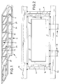
- FIG. 1 shows a support frame 1 for a semi-trailer, of horizontal strands 2 and 3, each horizontal strand 2 or 3 from an upper strand 2a or 3a and a lower strand 2b or 3b.
- the horizontal strands 2, 3 are reinforced by vertical cross strands 4 and additionally crossbars 27 are provided, which are now the strands Connect 2 and 3 together.
- the support frame 1 is designed as a vehicle frame, wherein in the finished state, the horizontal strands 2 and 3 with their upper and lower strands to the outside in the drawing Closure plates, not shown, are equipped, the enable so-called sliding effect or guardrail effect.
- Fig. 2 shows that in the embodiment of FIG. 1 in the space provided between the vertical transverse strands 4 a wheel carrier 6 is integrated, which on pivot bearings 16, 17 on lower horizontal strand 3b is pivotally mounted.
- the definition of the wheel carrier 6 is carried out except via the pivot bearing 16 and 17 on the horizontal strand 3b also via fastening screws 18 on the vertical cross strands 4 and the horizontal strand 3a.
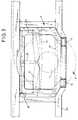
- FIG. 3 shows the arrangement according to FIG. 2, with here an arrangement is shown only as a structural component, in which the lower horizontal strand 3b in the area of the wheel carrier 6 is angled slightly downwards.
- the lower one Horizontal strand 3b in the area of the articulated mounting of the Wheel carrier 6 be interrupted and here a pivot axis wear on which the pivot bearings 16 and 17 attack.
- the lower horizontal strand 3b can also be used be continuous, then the pivot bearing 16, 17 encompass the lower horizontal strand 3b or attack on separate swivel axes.
- a wheel hub 7 is indicated, which carries a wheel 8, the is also only indicated schematically.
- the wheel hub 7 and the wheel 8 are firmly supported by a connecting support 9, whereby the connection carrier 9 ends in bearings supports for air bellows 10 and 11, which either on an inwardly projecting support plate 24 of the wheel carrier 6 support (Fig. 5) or on the underside of the upper Horizontal strands 3a can support.
- the connection carrier 9 ends in bearings supports for air bellows 10 and 11, which either on an inwardly projecting support plate 24 of the wheel carrier 6 support (Fig. 5) or on the underside of the upper Horizontal strands 3a can support.
- There are also trailing arms 14 and 15 recognizable and a shock absorber arrangement 26 without the invention in this embodiment in is limited in any way.
- the embodiment according to 3 is only intended to illustrate how it is possible to use the wheel 8 to be arranged on the wheel carrier 6. It is essential that it now, as shown in FIG.
- FIG. 5 and 6 show that with the new solution the loading volume is increased because in the area of FIGS. 5 and 6 body wall 28 shown created additional space that was previously occupied by axes.
- the wheel carrier 6 enters Swivel bearing 20 on which a connecting bracket 19 is pivotable attacks, which is connected to the wheel hub 7 and the other end, So opposite the pivot bearing 20, on an air bellows 12 supports, which in turn attached to the wheel carrier 6 can be.
- the independent wheel suspension on a wheel carrier 6 connects, the removable z. B. in the horizontal strand 2 or 3 of a support frame 1 is integrated, the horizontal strands 2 and 3 of the support frame 1, the actual wheel outside include and thereby the usual lead frame structure is left, in the two running in the longitudinal direction but essentially arranged within the wheels of the vehicle Beam widened outwards by crossbeams are.
Landscapes
- Engineering & Computer Science (AREA)
- Mechanical Engineering (AREA)
- Body Structure For Vehicles (AREA)
- Vehicle Body Suspensions (AREA)
Applications Claiming Priority (4)
| Application Number | Priority Date | Filing Date | Title |
|---|---|---|---|
| DE10008472 | 2000-02-24 | ||
| DE10008472 | 2000-02-24 | ||
| DE10010998 | 2000-03-07 | ||
| DE10010998A DE10010998C1 (de) | 2000-02-24 | 2000-03-07 | Schutzrahmenanordnung für Strassenfahrzeuge |
Publications (2)
| Publication Number | Publication Date |
|---|---|
| EP1127749A2 true EP1127749A2 (fr) | 2001-08-29 |
| EP1127749A3 EP1127749A3 (fr) | 2005-12-14 |
Family
ID=26004493
Family Applications (1)
| Application Number | Title | Priority Date | Filing Date |
|---|---|---|---|
| EP01103183A Withdrawn EP1127749A3 (fr) | 2000-02-24 | 2001-02-10 | Cadre de protection pour véhicules routiers |
Country Status (1)
| Country | Link |
|---|---|
| EP (1) | EP1127749A3 (fr) |
Cited By (1)
| Publication number | Priority date | Publication date | Assignee | Title |
|---|---|---|---|---|
| WO2004076263A1 (fr) * | 2003-02-27 | 2004-09-10 | Tg Consulting, Besloten Vennootschap Met Beperkte Aansprakelijkheid | Chassis de semi-remorque et suspension de roues |
Citations (3)
| Publication number | Priority date | Publication date | Assignee | Title |
|---|---|---|---|---|
| DE4317479A1 (de) | 1993-03-02 | 1994-09-08 | Schimmelpfennig Karl Heinz | Hauptrahmenanordnung für Straßenfahrzeuge |
| EP0650883A1 (fr) | 1993-10-27 | 1995-05-03 | ZF FRIEDRICHSHAFEN Aktiengesellschaft | Suspension indépendante |
| EP0638029B1 (fr) | 1993-03-02 | 1998-03-04 | SCHIMMELPFENNIG, Karl-Heinz | Cadre de protection pour vehicules routiers |
Family Cites Families (1)
| Publication number | Priority date | Publication date | Assignee | Title |
|---|---|---|---|---|
| DE10004227A1 (de) * | 2000-02-01 | 2001-08-02 | Bpw Bergische Achsen Kg | Radaufhängung für Fahrzeuge, insbesondere Nutzfahrzeuganhänger |
-
2001
- 2001-02-10 EP EP01103183A patent/EP1127749A3/fr not_active Withdrawn
Patent Citations (3)
| Publication number | Priority date | Publication date | Assignee | Title |
|---|---|---|---|---|
| DE4317479A1 (de) | 1993-03-02 | 1994-09-08 | Schimmelpfennig Karl Heinz | Hauptrahmenanordnung für Straßenfahrzeuge |
| EP0638029B1 (fr) | 1993-03-02 | 1998-03-04 | SCHIMMELPFENNIG, Karl-Heinz | Cadre de protection pour vehicules routiers |
| EP0650883A1 (fr) | 1993-10-27 | 1995-05-03 | ZF FRIEDRICHSHAFEN Aktiengesellschaft | Suspension indépendante |
Cited By (3)
| Publication number | Priority date | Publication date | Assignee | Title |
|---|---|---|---|---|
| WO2004076263A1 (fr) * | 2003-02-27 | 2004-09-10 | Tg Consulting, Besloten Vennootschap Met Beperkte Aansprakelijkheid | Chassis de semi-remorque et suspension de roues |
| BE1015391A3 (nl) * | 2003-02-27 | 2005-03-01 | Tg Consulting Bv Met Beperkte | Verbeterde oplegger. |
| CN100431899C (zh) * | 2003-02-27 | 2008-11-12 | Tg咨询有限责任公司 | 半拖车底盘及车轮悬架 |
Also Published As
| Publication number | Publication date |
|---|---|
| EP1127749A3 (fr) | 2005-12-14 |
Similar Documents
| Publication | Publication Date | Title |
|---|---|---|
| DE60013631T2 (de) | Vorderachsenanordnung für einen lastkraftwagen | |
| EP0290587B1 (fr) | Suspension indépendante pour un véhicule, particulièrement pour un autobus | |
| EP1404536A1 (fr) | Essieu arriere d'un vehicule automobile dote de cinq bras oscillants | |
| DE102004028161A1 (de) | Unterfahrschutz für Personenkraftfahrzeuge zur Anordnung unter Längsträgerniveau vor einem Hilfsrahmen oder Achsträger als zusätzliche Crashebene | |
| DE3437384A1 (de) | Fahrwerk fuer ein anhaengerfahrzeug | |
| DE3521361C2 (fr) | ||
| DE3807273C1 (fr) | ||
| EP0598353B1 (fr) | Train de roulement pour rames à plate-forme surbaissée | |
| EP1228949B1 (fr) | Véhicule automobile avec suspension indépendante et chassis auxiliaire | |
| DE19809281A1 (de) | Fahrgestell eines schweren Nutzfahrzeuges | |
| EP0940319B1 (fr) | Chassis d'un véhicule utilitaire lourd | |
| WO2014012636A1 (fr) | Suspension de roue pour le pont arrière d'un véhicule | |
| EP0895881B1 (fr) | Suspension à bras longitudinaux pour véhicules à moteur et remorques | |
| EP0650883A1 (fr) | Suspension indépendante | |
| DE10010998C1 (de) | Schutzrahmenanordnung für Strassenfahrzeuge | |
| EP1127749A2 (fr) | Cadre de protection pour véhicules routiers | |
| DE10011417B4 (de) | Einzelradaufhängung mit radführenden Schräglenkern | |
| EP0393419B1 (fr) | Direction pour véhicule automobile | |
| EP0940325B1 (fr) | Chassis pour véhicule utilitaire lourd | |
| EP0940322B1 (fr) | Chassis pour véhicule utilitaire lourd | |
| DE3340973A1 (de) | Kraftfahrzeug mit einem hilfsrahmen | |
| DE10035273C1 (de) | Schutzrahmenanordnung für Straßenfahrzeuge | |
| EP0225851B1 (fr) | Dispositif de suspension de roue pour un véhicule tous terrains à progression lente, en particulier pour voiture à traction par cheval | |
| EP0940323B1 (fr) | Chassis pour véhicule utilitaire lourd | |
| EP1157897B1 (fr) | Cadre de protection pour véhicules routiers |
Legal Events
| Date | Code | Title | Description |
|---|---|---|---|
| PUAI | Public reference made under article 153(3) epc to a published international application that has entered the european phase |
Free format text: ORIGINAL CODE: 0009012 |
|
| AK | Designated contracting states |
Kind code of ref document: A2 Designated state(s): AT BE CH CY DE DK ES FI FR GB GR IE IT LI LU MC NL PT SE TR |
|
| AX | Request for extension of the european patent |
Free format text: AL;LT;LV;MK;RO;SI |
|
| PUAL | Search report despatched |
Free format text: ORIGINAL CODE: 0009013 |
|
| AK | Designated contracting states |
Kind code of ref document: A3 Designated state(s): AT BE CH CY DE DK ES FI FR GB GR IE IT LI LU MC NL PT SE TR |
|
| AX | Request for extension of the european patent |
Extension state: AL LT LV MK RO SI |
|
| AKX | Designation fees paid | ||
| STAA | Information on the status of an ep patent application or granted ep patent |
Free format text: STATUS: THE APPLICATION IS DEEMED TO BE WITHDRAWN |
|
| 18D | Application deemed to be withdrawn |
Effective date: 20060615 |
|
| REG | Reference to a national code |
Ref country code: DE Ref legal event code: 8566 |