EP1127764A2 - Construction d'un modulateur de pression de freinage d'une remorque avec un système de freinage électronique - Google Patents
Construction d'un modulateur de pression de freinage d'une remorque avec un système de freinage électronique Download PDFInfo
- Publication number
- EP1127764A2 EP1127764A2 EP01100061A EP01100061A EP1127764A2 EP 1127764 A2 EP1127764 A2 EP 1127764A2 EP 01100061 A EP01100061 A EP 01100061A EP 01100061 A EP01100061 A EP 01100061A EP 1127764 A2 EP1127764 A2 EP 1127764A2
- Authority
- EP
- European Patent Office
- Prior art keywords
- valve
- control unit
- pressure
- pilot control
- pneumatic
- Prior art date
- Legal status (The legal status is an assumption and is not a legal conclusion. Google has not performed a legal analysis and makes no representation as to the accuracy of the status listed.)
- Granted
Links
Images


Classifications
-
- F—MECHANICAL ENGINEERING; LIGHTING; HEATING; WEAPONS; BLASTING
- F15—FLUID-PRESSURE ACTUATORS; HYDRAULICS OR PNEUMATICS IN GENERAL
- F15B—SYSTEMS ACTING BY MEANS OF FLUIDS IN GENERAL; FLUID-PRESSURE ACTUATORS, e.g. SERVOMOTORS; DETAILS OF FLUID-PRESSURE SYSTEMS, NOT OTHERWISE PROVIDED FOR
- F15B13/00—Details of servomotor systems ; Valves for servomotor systems
- F15B13/02—Fluid distribution or supply devices characterised by their adaptation to the control of servomotors
- F15B13/06—Fluid distribution or supply devices characterised by their adaptation to the control of servomotors for use with two or more servomotors
- F15B13/08—Assemblies of units, each for the control of a single servomotor only
- F15B13/0803—Modular units
- F15B13/0832—Modular valves
- F15B13/0842—Monoblock type valves, e.g. with multiple valve spools in a common housing
-
- B—PERFORMING OPERATIONS; TRANSPORTING
- B60—VEHICLES IN GENERAL
- B60T—VEHICLE BRAKE CONTROL SYSTEMS OR PARTS THEREOF; BRAKE CONTROL SYSTEMS OR PARTS THEREOF, IN GENERAL; ARRANGEMENT OF BRAKING ELEMENTS ON VEHICLES IN GENERAL; PORTABLE DEVICES FOR PREVENTING UNWANTED MOVEMENT OF VEHICLES; VEHICLE MODIFICATIONS TO FACILITATE COOLING OF BRAKES
- B60T13/00—Transmitting braking action from initiating means to ultimate brake actuator with power assistance or drive; Brake systems incorporating such transmitting means, e.g. air-pressure brake systems
- B60T13/10—Transmitting braking action from initiating means to ultimate brake actuator with power assistance or drive; Brake systems incorporating such transmitting means, e.g. air-pressure brake systems with fluid assistance, drive, or release
- B60T13/66—Electrical control in fluid-pressure brake systems
- B60T13/68—Electrical control in fluid-pressure brake systems by electrically-controlled valves
- B60T13/683—Electrical control in fluid-pressure brake systems by electrically-controlled valves in pneumatic systems or parts thereof
-
- B—PERFORMING OPERATIONS; TRANSPORTING
- B60—VEHICLES IN GENERAL
- B60T—VEHICLE BRAKE CONTROL SYSTEMS OR PARTS THEREOF; BRAKE CONTROL SYSTEMS OR PARTS THEREOF, IN GENERAL; ARRANGEMENT OF BRAKING ELEMENTS ON VEHICLES IN GENERAL; PORTABLE DEVICES FOR PREVENTING UNWANTED MOVEMENT OF VEHICLES; VEHICLE MODIFICATIONS TO FACILITATE COOLING OF BRAKES
- B60T15/00—Construction arrangement, or operation of valves incorporated in power brake systems and not covered by groups B60T11/00 or B60T13/00
- B60T15/02—Application and release valves
- B60T15/025—Electrically controlled valves
- B60T15/027—Electrically controlled valves in pneumatic systems
-
- B—PERFORMING OPERATIONS; TRANSPORTING
- B60—VEHICLES IN GENERAL
- B60T—VEHICLE BRAKE CONTROL SYSTEMS OR PARTS THEREOF; BRAKE CONTROL SYSTEMS OR PARTS THEREOF, IN GENERAL; ARRANGEMENT OF BRAKING ELEMENTS ON VEHICLES IN GENERAL; PORTABLE DEVICES FOR PREVENTING UNWANTED MOVEMENT OF VEHICLES; VEHICLE MODIFICATIONS TO FACILITATE COOLING OF BRAKES
- B60T8/00—Arrangements for adjusting wheel-braking force to meet varying vehicular or ground-surface conditions, e.g. limiting or varying distribution of braking force
- B60T8/32—Arrangements for adjusting wheel-braking force to meet varying vehicular or ground-surface conditions, e.g. limiting or varying distribution of braking force responsive to a speed condition, e.g. acceleration or deceleration
- B60T8/321—Arrangements for adjusting wheel-braking force to meet varying vehicular or ground-surface conditions, e.g. limiting or varying distribution of braking force responsive to a speed condition, e.g. acceleration or deceleration deceleration
- B60T8/323—Systems specially adapted for tractor-trailer combinations
-
- B—PERFORMING OPERATIONS; TRANSPORTING
- B60—VEHICLES IN GENERAL
- B60T—VEHICLE BRAKE CONTROL SYSTEMS OR PARTS THEREOF; BRAKE CONTROL SYSTEMS OR PARTS THEREOF, IN GENERAL; ARRANGEMENT OF BRAKING ELEMENTS ON VEHICLES IN GENERAL; PORTABLE DEVICES FOR PREVENTING UNWANTED MOVEMENT OF VEHICLES; VEHICLE MODIFICATIONS TO FACILITATE COOLING OF BRAKES
- B60T8/00—Arrangements for adjusting wheel-braking force to meet varying vehicular or ground-surface conditions, e.g. limiting or varying distribution of braking force
- B60T8/32—Arrangements for adjusting wheel-braking force to meet varying vehicular or ground-surface conditions, e.g. limiting or varying distribution of braking force responsive to a speed condition, e.g. acceleration or deceleration
- B60T8/321—Arrangements for adjusting wheel-braking force to meet varying vehicular or ground-surface conditions, e.g. limiting or varying distribution of braking force responsive to a speed condition, e.g. acceleration or deceleration deceleration
- B60T8/3255—Systems in which the braking action is dependent on brake pedal data
- B60T8/327—Pneumatic systems
-
- B—PERFORMING OPERATIONS; TRANSPORTING
- B60—VEHICLES IN GENERAL
- B60T—VEHICLE BRAKE CONTROL SYSTEMS OR PARTS THEREOF; BRAKE CONTROL SYSTEMS OR PARTS THEREOF, IN GENERAL; ARRANGEMENT OF BRAKING ELEMENTS ON VEHICLES IN GENERAL; PORTABLE DEVICES FOR PREVENTING UNWANTED MOVEMENT OF VEHICLES; VEHICLE MODIFICATIONS TO FACILITATE COOLING OF BRAKES
- B60T8/00—Arrangements for adjusting wheel-braking force to meet varying vehicular or ground-surface conditions, e.g. limiting or varying distribution of braking force
- B60T8/32—Arrangements for adjusting wheel-braking force to meet varying vehicular or ground-surface conditions, e.g. limiting or varying distribution of braking force responsive to a speed condition, e.g. acceleration or deceleration
- B60T8/34—Arrangements for adjusting wheel-braking force to meet varying vehicular or ground-surface conditions, e.g. limiting or varying distribution of braking force responsive to a speed condition, e.g. acceleration or deceleration having a fluid pressure regulator responsive to a speed condition
- B60T8/36—Arrangements for adjusting wheel-braking force to meet varying vehicular or ground-surface conditions, e.g. limiting or varying distribution of braking force responsive to a speed condition, e.g. acceleration or deceleration having a fluid pressure regulator responsive to a speed condition including a pilot valve responding to an electromagnetic force
- B60T8/3615—Electromagnetic valves specially adapted for anti-lock brake and traction control systems
- B60T8/3675—Electromagnetic valves specially adapted for anti-lock brake and traction control systems integrated in modulator units
-
- F—MECHANICAL ENGINEERING; LIGHTING; HEATING; WEAPONS; BLASTING
- F15—FLUID-PRESSURE ACTUATORS; HYDRAULICS OR PNEUMATICS IN GENERAL
- F15B—SYSTEMS ACTING BY MEANS OF FLUIDS IN GENERAL; FLUID-PRESSURE ACTUATORS, e.g. SERVOMOTORS; DETAILS OF FLUID-PRESSURE SYSTEMS, NOT OTHERWISE PROVIDED FOR
- F15B13/00—Details of servomotor systems ; Valves for servomotor systems
- F15B13/02—Fluid distribution or supply devices characterised by their adaptation to the control of servomotors
- F15B13/06—Fluid distribution or supply devices characterised by their adaptation to the control of servomotors for use with two or more servomotors
- F15B13/08—Assemblies of units, each for the control of a single servomotor only
- F15B13/0803—Modular units
- F15B13/0846—Electrical details
- F15B13/0853—Electric circuit boards
-
- F—MECHANICAL ENGINEERING; LIGHTING; HEATING; WEAPONS; BLASTING
- F15—FLUID-PRESSURE ACTUATORS; HYDRAULICS OR PNEUMATICS IN GENERAL
- F15B—SYSTEMS ACTING BY MEANS OF FLUIDS IN GENERAL; FLUID-PRESSURE ACTUATORS, e.g. SERVOMOTORS; DETAILS OF FLUID-PRESSURE SYSTEMS, NOT OTHERWISE PROVIDED FOR
- F15B13/00—Details of servomotor systems ; Valves for servomotor systems
- F15B13/02—Fluid distribution or supply devices characterised by their adaptation to the control of servomotors
- F15B13/06—Fluid distribution or supply devices characterised by their adaptation to the control of servomotors for use with two or more servomotors
- F15B13/08—Assemblies of units, each for the control of a single servomotor only
- F15B13/0803—Modular units
- F15B13/0846—Electrical details
- F15B13/0857—Electrical connecting means, e.g. plugs, sockets
-
- F—MECHANICAL ENGINEERING; LIGHTING; HEATING; WEAPONS; BLASTING
- F15—FLUID-PRESSURE ACTUATORS; HYDRAULICS OR PNEUMATICS IN GENERAL
- F15B—SYSTEMS ACTING BY MEANS OF FLUIDS IN GENERAL; FLUID-PRESSURE ACTUATORS, e.g. SERVOMOTORS; DETAILS OF FLUID-PRESSURE SYSTEMS, NOT OTHERWISE PROVIDED FOR
- F15B13/00—Details of servomotor systems ; Valves for servomotor systems
- F15B13/02—Fluid distribution or supply devices characterised by their adaptation to the control of servomotors
- F15B13/06—Fluid distribution or supply devices characterised by their adaptation to the control of servomotors for use with two or more servomotors
- F15B13/08—Assemblies of units, each for the control of a single servomotor only
- F15B13/0803—Modular units
- F15B13/0846—Electrical details
- F15B13/086—Sensing means, e.g. pressure sensors
-
- F—MECHANICAL ENGINEERING; LIGHTING; HEATING; WEAPONS; BLASTING
- F15—FLUID-PRESSURE ACTUATORS; HYDRAULICS OR PNEUMATICS IN GENERAL
- F15B—SYSTEMS ACTING BY MEANS OF FLUIDS IN GENERAL; FLUID-PRESSURE ACTUATORS, e.g. SERVOMOTORS; DETAILS OF FLUID-PRESSURE SYSTEMS, NOT OTHERWISE PROVIDED FOR
- F15B13/00—Details of servomotor systems ; Valves for servomotor systems
- F15B13/02—Fluid distribution or supply devices characterised by their adaptation to the control of servomotors
- F15B13/06—Fluid distribution or supply devices characterised by their adaptation to the control of servomotors for use with two or more servomotors
- F15B13/08—Assemblies of units, each for the control of a single servomotor only
- F15B13/0803—Modular units
- F15B13/0878—Assembly of modular units
- F15B13/0896—Assembly of modular units using different types or sizes of valves
-
- F—MECHANICAL ENGINEERING; LIGHTING; HEATING; WEAPONS; BLASTING
- F16—ENGINEERING ELEMENTS AND UNITS; GENERAL MEASURES FOR PRODUCING AND MAINTAINING EFFECTIVE FUNCTIONING OF MACHINES OR INSTALLATIONS; THERMAL INSULATION IN GENERAL
- F16K—VALVES; TAPS; COCKS; ACTUATING-FLOATS; DEVICES FOR VENTING OR AERATING
- F16K27/00—Construction of housing; Use of materials therefor
- F16K27/003—Housing formed from a plurality of the same valve elements
-
- F—MECHANICAL ENGINEERING; LIGHTING; HEATING; WEAPONS; BLASTING
- F16—ENGINEERING ELEMENTS AND UNITS; GENERAL MEASURES FOR PRODUCING AND MAINTAINING EFFECTIVE FUNCTIONING OF MACHINES OR INSTALLATIONS; THERMAL INSULATION IN GENERAL
- F16K—VALVES; TAPS; COCKS; ACTUATING-FLOATS; DEVICES FOR VENTING OR AERATING
- F16K31/00—Actuating devices; Operating means; Releasing devices
- F16K31/02—Actuating devices; Operating means; Releasing devices electric; magnetic
- F16K31/06—Actuating devices; Operating means; Releasing devices electric; magnetic using a magnet, e.g. diaphragm valves, cutting off by means of a liquid
-
- Y—GENERAL TAGGING OF NEW TECHNOLOGICAL DEVELOPMENTS; GENERAL TAGGING OF CROSS-SECTIONAL TECHNOLOGIES SPANNING OVER SEVERAL SECTIONS OF THE IPC; TECHNICAL SUBJECTS COVERED BY FORMER USPC CROSS-REFERENCE ART COLLECTIONS [XRACs] AND DIGESTS
- Y10—TECHNICAL SUBJECTS COVERED BY FORMER USPC
- Y10T—TECHNICAL SUBJECTS COVERED BY FORMER US CLASSIFICATION
- Y10T137/00—Fluid handling
- Y10T137/8593—Systems
- Y10T137/87169—Supply and exhaust
- Y10T137/87217—Motor
Definitions
- the invention relates to a brake pressure modulator.
- the well-known font shows a two-channel pressure control module [there Fig. 2], in which for both channels as a switching valve a common 3/2-way solenoid valve [there (12)] is provided to the other solenoid valves leading line [there (15)] either with the supply pressure [there (17) in the actuated state of the valve (12)] or with a control pressure [there (13) in unactuated State of the valve (12)] connects; for the following assume that the 3/2-way solenoid valve is actuated is so that the supply pressure at the other solenoid valves is present - this represents the case of pressure regulation represents.
- One of the two is symmetrically constructed Pressure control loops, namely the one for which the Valves (9 '), (7), (3) are provided.
- the 3/2-way solenoid valve [there (9 ')] gives the direction of the pressure change in front; in unactuated condition [as in this drawing shown] there is an increase in pressure since the supply pressure is effective, in the actuated state there is a Lowering through the connection with the ventilation [there (11 ')].
- the 2/2-way solenoid valve is connected in series with this valve [there (7)] that's either a connection to a control input of the subsequent relay valve produces [there control input (5) in the drawn, valve position not actuated] or this control input completes [actuated valve position].
- the invention is therefore based on the object Pilot control unit for a brake pressure modulator at the beginning mentioned type to change such that the manufacturing costs be reduced.
- the invention has the advantage that the pilot control unit for a pressure control loop over three very similarly constructed 2/2-way solenoid valves.
- Another development of the invention has the advantage that by the choice of metallic sealing seats the magnet armatures for the energized state of the solenoid valves are particularly space-saving.
- the usage such sealing seat is through a specially trained pneumatic circuit technology possible.
- An electronically controlled braking system [EBS] for trailer vehicles has several independently Working brake control loops for the vehicle's wheel brakes [multi-channel system].
- a brake control loop that represents a pressure control channel for a wheel brake from a pilot control unit consisting of solenoid valves is built up from an air quantity increasing relay valve, from at least one brake cylinder for the wheel brakes, one placed in a suitable place Brake pressure sensor and from an electronic control device, which carries out the brake pressure control.
- the brake control loops for the different channels of the multi-circuit systems are constructed in the same way, so that with the description of one brake control circuit the others Brake control loops are also described.
- the embodiment is therefore the configuration of a basic variant for trailer EBS systems, which consists of a semi-trailer with two axles is a 4S / 2M system [four ABS sensors for four wheels and two modulator channels for the wheel brakes the left or right side]; the brake pressure control is carried out page by page.
- the EBS trailer vehicle is with an EBS towing vehicle via an electrical and a pneumatic interface connected.
- the electrical interface exists from the digital data interface according to ISO 1199-2; the pneumatic interface consists firstly of the supply line, which supplies the trailer with compressed air and second, the brake line that is in the trailer with a Trailer brake valve is connected.
- the trailer brake valve controls one at its pneumatic output Brake pressure from that on the pneumatic brake line transmitted brake pressure is derived and this corresponds.
- the demolition protection is implemented as it is of conventionally braked vehicle trains [towing vehicle trailer vehicle] is known; with such a demolition is in the known manner from the trailer brake valve also controlled a brake pressure.
- the EBS trailer vehicle can also be behind a towing vehicle can be operated with a conventional brake system.
- this is used by the trailer brake valve controlled pressure for pneumatically redundant braking in the event of an EBS failure; it also serves using a pressure sensor arranged in the trailer brake valve to determine the electrical setpoint for the case that the EBS trailer on a conventional Towing vehicle, d. H. operated on a non-EBS towing vehicle becomes.
- This modulated pressure represents the redundancy pressure represents.
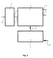
- the block diagram for the brake pressure modulator are the pilot control unit (1) and the functional units, with which the pilot control unit interacts, namely the electronic control unit (3) and the air quantity increasing Relay valve (2) shown.
- the pilot control unit (1) has a first pneumatic one Inlet (4) connected to the supply pressure and via a second pneumatic input (5) that with the pneumatic output of the not shown Trailer brake valves for transferring the redundancy pressure connected is.
- a pneumatic outlet (6) the pilot control unit (1) is connected to the input (17) of the relay valve (2) connected.
- the electrical interface is via a line (20) with the electrical control unit (3) for transmission the electrical braking value specification and there are starting from the electronic control unit (3) electrical Control lines (19) for the solenoid valves of the Pilot control unit (1) provided.
- the pneumatic output (18) of the relay valve (2) is with the brake cylinders, not shown, for this Brake control loop connected.
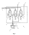
- a first solenoid valve (7) has a first connection (10) and a second Connection (11)
- a second solenoid valve (8) has a first port (12) and a second port (13)
- a third solenoid valve (9) has one first connection (14) and a second connection (15).
- the first port (10) of the first solenoid valve (7) is with the first pneumatic input (4) of the pilot control unit (1) connected, the first connector (12) of the second Solenoid valve (8) is pneumatic with the second Input of the pilot control unit (1) connected, the second Connection (11) of the first solenoid valve (7) is connected to the pneumatic output (6) of the pilot control unit (1) connected, the second connection (13) of the second solenoid valve (8) is with the first connection (14) of the third solenoid valve (9) and the pneumatic output (6) of the Pilot control unit (1) connected and the second output (15) of the third solenoid valve (9) is with a pressure sink (16) connected.
- the first solenoid valve (7) and the third solenoid valve (9) are normally closed 2/2-way solenoid valves designed while the second solenoid valve (8) as normally open 2/2-way solenoid valve is formed.
- the solenoid valves (7), (8), (9), the pilot control unit (1) are used to determine the pressure in the control chamber of the Relay valves (2); they are in clocked mode to operate.
- the second solenoid valve (8) is used to transmit the Redundancy pressure in the control chamber of the relay valve (2), the control chamber pressure follows when de-energized, if the other solenoid valves (7) and (9) are not are actuated, the at the second pneumatic input (5) the pilot control unit (1) applied redundancy pressure; this Redundancy pressure valve thus serves both as a ventilation as well as a vent valve for the control chamber pressure. This separates when de-energized second solenoid valve (8) the redundancy pressure from the control chamber the relay valve (2).
- the first solenoid valve (7) is through its connection with the supply pressure as aeration and the third solenoid valve (9) is through its connection to the pressure sink as a vent valve for the control chamber of the relay valve (2) provided.
- the solenoid valves (7), (8) and (9) are in contrast to Series connection of valves according to the above Font connected in parallel to each other, which also makes them can be operated simultaneously.
- FIG. 3 the construction of the solenoid valves in one Valve block shown with its piping.
- the magnetic anchor (25) of the solenoid valve (7) is identical in construction the magnet armature (26) of the solenoid valve (8) and Magnet armature (27) of the solenoid valve (9) built up;
- the Solenoid coil (28) of the solenoid valve (7) is also identical to the solenoid (29) of the solenoid valve (8) and built up to the solenoid (30) of the solenoid valve (9).
- the interconnection of the connections (11), (13) and (14) the pneumatic output (6) of the pilot control unit (1) represents.
- the magnetic coils contain magnetic flux-concentrating ferromagnetic Yokes that suitably use the magnetic force increase.
- the housing of the valve block in which the solenoid coils are installed, there are also magnetic flux concentrating Elements that reinforce magnetic force act and in a suitable form, e.g. B. from ferromagnetic Materials are made.
- the magnetic flux concentrators are for a better overview Elements as part of the valve block housing or the magnetic coils (28), (29), (30) not shown.
- Fig. 3 are further dashed for the valve block Form a first parting line (60) and a second parting line (61) indicated.
- the first parting line serves to separate a first connection part (51) from The valve block and the second parting line are used for separation a second connector (52) so that between the Parting lines a triple solenoid unit is formed; this represents an embodiment of the invention that is related with the explanations for Fig. 5 described is.
- Fig. 4 is shown how using similar Magnet armature solenoid valves with different functions can be realized.
- the reference numerals are for the individual valve variants chosen uniformly so that they from one valve construction to another valve construction are directly transferable.
- the next valve variant is a normally open one 2/2-way solenoid valve, which is under the reference numeral (45) is drawn in the de-energized switching state.
- the effect of the magnetic armature return spring (40) is the magnetic armature at a stroke limitation (32) to the system, however in this case not designed with a sealing seat is.
- the first connection is in this switch position (35) connected to the second terminal (36).
- the normally open 2/2-way solenoid valve is under the Reference numerals (46) drawn in the energized switching state.
- the magnet armature (39) comes at a stroke limitation (34) to the plant and forms at this point through the Forming (42) of the magnet armature with the second connection (36) a metal-metal valve: the first connection (35) is separated from the second connection (36).
- the metal-metal valve seat is in contrast to the above Valve seat using the elastomer insert (41) not hermetically sealed, d. H. leaks occur. As explained below, the circuit technology for the Use of this valve chosen such that this leakage are meaningless.
- the 3/2-way solenoid valve drawn in the energized switching state.
- the anchor comes along with the stroke limiter (34) the second connection (36) to the system and forms with the Forming (42) a metal-metal sealing seat.
- the first connection (35) is separated from the second connection (36), however, the first port (35) is with the third connection (37) connected.
- the redundancy pressure valve (8) is actuated and the redundant pressure at the second pneumatic input (5) is separated from the relay valve control chamber [pneumatic output (6)] via the metal-metal valve seat that is in this switching state.
- the leakage cross section on the one hand is extremely small compared to the valve cross sections and on the other hand becomes a Clocking performed in a closed control loop, namely such that it is clocked up and down until the on pneumatic output (18) of the relay valve (2)
- Brake pressure one from the electronic control unit calculated brake pressure setpoint corresponds to [the calculation the brake pressure setpoint in the electronic
- the control unit is located next to the electrical braking value specification through the electrical interface which the The main target represents further influencing factors through the Load or ABS braking control].
- valves must be used in pilot controls usually equip with a nominal width of approx. 2.2 mm, to avoid that through the compressed air pilot lines, which increases the spatial distance of a valve bridge the pressure-accumulating relay valve control chamber, a large pressure drop occurs.
- the acceleration resistance of the formation on the metallic sealing seat is ensured by the fact that is provided with a coating, as in the DE-A1-197 30 276 is specified.
- the Nominal size of a solenoid valve to a value of 1.7 mm be reduced, which is an optimal value for a pilot valve in vehicle applications: It guarantees on the one hand, good gradability for the modulated Brake pressure and on the other hand it's not so small that the usual pollution of compressed air in vehicles already play a role.
- the switching times can be adjusted using the measures described reduce for the solenoid valves to approx. 6 ms. With The reduced switching times can change quickly Setpoint specifications for the brake pressure regulator can be realized and at the output (18) of the relay valve (2) are high Gradients for the modulated brake pressure can be realized.
- FIG. 5 An advantageous development of the design of the solenoid valves 3 is shown in FIG. 5.
- the solenoids (28), (29) and (30) for the solenoid valves (7), (8) and (9) can be due to their identical Design for the compact triple solenoid unit (49) summarize that for stabilization with a plastic (50) is overmolded.
- the connecting parts (51) and (52) contain holes, such as 3 for the piping of the solenoid valves (7), (8) and (9) are described [they are for clarity 5 itself not shown], so that with the production of the sealing connections the whole Pre-control unit is manufactured ready for installation.
- the board (55) can be used
- Fastening means (56) can be fixed as a component. This creates an electronic-pneumatic assembly, which the pilot control unit and the electronic Control unit includes; this assembly then only has to structurally combined with larger parts such as the relay valves to the trailer brake pressure modulator on the 3-fold solenoid unit (49) to be completed.
Landscapes
- Engineering & Computer Science (AREA)
- Mechanical Engineering (AREA)
- General Engineering & Computer Science (AREA)
- Physics & Mathematics (AREA)
- Fluid Mechanics (AREA)
- Transportation (AREA)
- Electromagnetism (AREA)
- Valves And Accessory Devices For Braking Systems (AREA)
- Regulating Braking Force (AREA)
- Braking Systems And Boosters (AREA)
Applications Claiming Priority (2)
| Application Number | Priority Date | Filing Date | Title |
|---|---|---|---|
| DE10009117 | 2000-02-26 | ||
| DE10009117A DE10009117B4 (de) | 2000-02-26 | 2000-02-26 | Konstruktion eines Bremsdruckmodulators für Anhänger mit elektronischer Bremsanlage |
Publications (3)
| Publication Number | Publication Date |
|---|---|
| EP1127764A2 true EP1127764A2 (fr) | 2001-08-29 |
| EP1127764A3 EP1127764A3 (fr) | 2001-09-05 |
| EP1127764B1 EP1127764B1 (fr) | 2004-09-08 |
Family
ID=7632535
Family Applications (1)
| Application Number | Title | Priority Date | Filing Date |
|---|---|---|---|
| EP01100061A Expired - Lifetime EP1127764B1 (fr) | 2000-02-26 | 2001-01-10 | Construction d'un modulateur de pression de freinage d'une remorque avec un système de freinage électronique |
Country Status (4)
| Country | Link |
|---|---|
| US (1) | US6467854B2 (fr) |
| EP (1) | EP1127764B1 (fr) |
| JP (1) | JP2001247032A (fr) |
| DE (2) | DE10009117B4 (fr) |
Cited By (4)
| Publication number | Priority date | Publication date | Assignee | Title |
|---|---|---|---|---|
| WO2008034525A1 (fr) * | 2006-09-20 | 2008-03-27 | Wabco Gmbh | Unité de commande à valves, notamment unité de précommande pour un modulateur de pression sur un véhicule industriel |
| EP3822134A1 (fr) | 2019-11-18 | 2021-05-19 | KNORR-BREMSE Systeme für Nutzfahrzeuge GmbH | Système de freinage pour véhicule à moteur et module de commande de remorque |
| EP3822133A1 (fr) | 2019-11-18 | 2021-05-19 | KNORR-BREMSE Systeme für Nutzfahrzeuge GmbH | Système de freinage pour véhicule à moteur et module d'alimentation en air et de commande de remorque |
| CN114616145A (zh) * | 2019-10-30 | 2022-06-10 | 克诺尔商用车制动系统有限公司 | 用于车辆的制动系统的切换装置、具有切换装置的制动系统和切换装置的运行方法 |
Families Citing this family (27)
| Publication number | Priority date | Publication date | Assignee | Title |
|---|---|---|---|---|
| DE10113316A1 (de) * | 2001-03-20 | 2002-09-26 | Wabco Gmbh & Co Ohg | Herstellverfahren für Magnetanker |
| KR100710477B1 (ko) * | 2002-07-11 | 2007-04-23 | 주식회사 만도 | 전자제어식 브레이크 시스템용 전자제어유닛의 흡배기장치 |
| CN100436217C (zh) * | 2004-05-28 | 2008-11-26 | 外博泰克控股股份有限公司 | 制动阀电控气动总管 |
| DE102004035763A1 (de) * | 2004-07-21 | 2006-03-16 | Wabco Gmbh & Co.Ohg | Bremsdruckmodulator-Vorsteuereinheit |
| DE202006004749U1 (de) * | 2006-03-24 | 2006-06-29 | Bürkert Werke GmbH & Co. KG | Vorrichtung und Ventilkombination zur Fließumkehr von strömenden Medien |
| DE102008007524B4 (de) | 2008-02-05 | 2023-03-30 | Zf Cv Systems Hannover Gmbh | Vorrichtung zum Betreiben einer Bremse |
| DE102008028440A1 (de) * | 2008-06-17 | 2009-12-31 | Knorr-Bremse Systeme für Nutzfahrzeuge GmbH | Drucksteuerventilanordnung mit Membranventilen zur Steuerung eines Fluiddrucks in einer ABS-Bremsanlage eines Fahrzeugs mit in einem Gehäuseteil einstückig integriertem Ventilsitz |
| FR2965034B1 (fr) * | 2010-09-16 | 2014-04-18 | Peugeot Citroen Automobiles Sa | Dispositif hydraulique pour systeme de transmission de vehicule |
| US8888802B2 (en) | 2010-12-21 | 2014-11-18 | Alcon Research, Ltd. | Vitrectomy probe with adjustable cutter port size |
| US9101441B2 (en) | 2010-12-21 | 2015-08-11 | Alcon Research, Ltd. | Vitrectomy probe with adjustable cutter port size |
| US8747426B2 (en) | 2011-12-20 | 2014-06-10 | Alcon Research, Ltd. | Vitrectomy probe with adjustable cutter port size |
| US9664296B2 (en) * | 2014-01-02 | 2017-05-30 | Curtis Roys | Check valve |
| DE102014002614A1 (de) * | 2014-02-27 | 2015-08-27 | Wabco Gmbh | Bremsmodul für ein hydraulisch gebremstes Zugfahrzeug, welches mit einem pneumatisch gebremsten Anhängefahrzeug koppelbar ist. |
| DE102014011422A1 (de) * | 2014-07-31 | 2016-02-04 | Wabco Gmbh | Bremsdruckmodulator eines elektronischen Bremssystems eines Nutzfahrzeugs |
| CN104192114B (zh) * | 2014-08-25 | 2016-08-24 | 北京理工大学 | 一种车辆电控气压制动系统 |
| US9611980B2 (en) | 2014-10-01 | 2017-04-04 | Curtis Roys | Check valve |
| US9353742B2 (en) | 2014-10-01 | 2016-05-31 | Curtis Roys | Check valve |
| CN106515701B (zh) * | 2016-08-30 | 2023-08-01 | 浙江万安科技股份有限公司 | 一种电子制动控制阀、简化型ebs制动系统及制动方法 |
| CN106494378B (zh) * | 2016-09-21 | 2017-09-01 | 比亚迪股份有限公司 | 轨道车辆及其空气制动系统、轨道交通系统 |
| DE102018108091A1 (de) * | 2018-04-05 | 2019-10-10 | Wabco Gmbh | Elektropneumatisches Bremssteuermodul für Nutzfahrzeuge mit Redundanzdruckanschluss |
| US11053670B2 (en) | 2018-08-23 | 2021-07-06 | Spectrum Brands, Inc. | Faucet spray head alignment system |
| CN112639227B (zh) | 2018-08-23 | 2023-02-28 | 品谱股份有限公司 | 水龙头喷头对准系统 |
| JP7438979B2 (ja) * | 2018-12-28 | 2024-02-27 | ナブテスコオートモーティブ株式会社 | 空気供給回路 |
| DE102019101791A1 (de) * | 2019-01-24 | 2020-07-30 | Rapa Automotive Gmbh & Co. Kg | Ventilblock mit Füllanschluss |
| US12460733B2 (en) | 2022-04-09 | 2025-11-04 | Curtis Alan Roys | Divider block system and balancing valve for divider block system |
| GB2622385A (en) * | 2022-09-14 | 2024-03-20 | Knorr Bremse Systeme Fuer Nutzfahrzeuge Gmbh | Relay valve arrangement for a trailer brake system |
| DE102023110039A1 (de) | 2023-04-20 | 2024-10-24 | Zf Cv Systems Global Gmbh | Bremsdruckmodulator und Verfahren zu dessen Steuerung |
Family Cites Families (28)
| Publication number | Priority date | Publication date | Assignee | Title |
|---|---|---|---|---|
| DE2113001B1 (de) * | 1971-03-18 | 1972-02-03 | Westinghouse Bremsen Und Appba | Elektromagnetisch betaetigtes Entlueftungsventil mit hoher Beschleunigung |
| CA1079609A (fr) * | 1976-12-27 | 1980-06-17 | Larry A. Williamson | Robinet pilote a solenoide |
| US4102526A (en) | 1977-02-23 | 1978-07-25 | Hargraves Donald E | Solenoid valve |
| US4245815A (en) | 1979-02-23 | 1981-01-20 | Linear Dynamics, Inc. | Proportional solenoid valve and connector |
| DE3308279A1 (de) | 1983-03-09 | 1984-09-13 | Robert Bosch Gmbh, 7000 Stuttgart | Motorwagen-bremsventil |
| JPS6467460A (en) * | 1987-09-09 | 1989-03-14 | Isuzu Motors Ltd | Traction control system |
| US5127434A (en) | 1989-03-17 | 1992-07-07 | Coltec Industries Inc. | Control module having multiple solenoid actuated valves |
| DE3930568A1 (de) * | 1989-09-13 | 1991-03-14 | Bosch Gmbh Robert | Druckluftbremsanlage mit einer blockierschutzeinrichtung |
| DE4030980A1 (de) * | 1990-10-01 | 1992-04-02 | Bosch Gmbh Robert | Elektropneumatische bremsanlage |
| EP0499670B1 (fr) | 1991-02-20 | 1995-10-11 | Siemens Aktiengesellschaft | Dispositif de commande de valves |
| DE4227084B4 (de) * | 1992-08-17 | 2004-03-25 | Knorr-Bremse Systeme für Nutzfahrzeuge GmbH | Druckregelmodul einer Druckluft-Fahrzeugbremsanlage |
| JP3147684B2 (ja) | 1994-02-15 | 2001-03-19 | トヨタ自動車株式会社 | 電磁弁の製造方法 |
| JPH09126207A (ja) | 1995-10-31 | 1997-05-13 | Aisin Seiki Co Ltd | 圧力制御装置 |
| DE19609222A1 (de) * | 1996-03-09 | 1997-09-11 | Bosch Gmbh Robert | Anhängersteuerventil für eine Druckluftbremsanlage für Kraftfahrzeuge |
| DE19636432B4 (de) * | 1996-09-07 | 2007-08-16 | Robert Bosch Gmbh | Hydraulische Fremdkraft-Fahrzeugbremsanlage |
| DE19637484A1 (de) * | 1996-09-14 | 1998-03-19 | Wabco Gmbh | Zweileitungs-Anhängerbremsanlage |
| FR2754572A1 (fr) | 1996-10-15 | 1998-04-17 | Peugeot | Agencement d'electrovanne pourvu d'un dispositif de fixation sur un support et bloc hydraulique equipe d'un tel agencement |
| US5845672A (en) | 1996-12-10 | 1998-12-08 | General Motors Corporation | Solenoid coil positioning assembly |
| DE19704152C2 (de) * | 1997-02-04 | 1998-11-05 | Siemens Ag | Steuergerät für ein Antiblockiersystem |
| JP4255038B2 (ja) * | 1997-06-27 | 2009-04-15 | クノールブレムゼ商用車システムジャパン株式会社 | 坂道発進補助装置を備えたブレーキ制御システムおよびこのシステムに用いられる電磁デュアルリレーバルブ |
| DE19730276A1 (de) * | 1997-07-15 | 1999-01-21 | Wabco Gmbh | Einrichtung mit wenigstens zwei relativ zueinander beweglichen Teilen |
| FR2766546B1 (fr) | 1997-07-22 | 1999-10-22 | Peugeot | Agencement d'electrovanne a moyen de fixation elastique sur son support, tel qu'un bloc hydraulique |
| JPH1182800A (ja) * | 1997-08-29 | 1999-03-26 | Unisia Jecs Corp | 電磁弁 |
| JPH1178833A (ja) * | 1997-09-02 | 1999-03-23 | Akebono Brake Ind Co Ltd | ブレーキ圧制御装置 |
| US6000679A (en) * | 1997-12-11 | 1999-12-14 | General Motors Corporation | Solenoid coil attachment mechanism |
| US6086042A (en) | 1998-04-08 | 2000-07-11 | Wabash Magnetics, Inc. | Fluid resistant solenoid actuated valve |
| DE19918070B4 (de) * | 1998-06-03 | 2010-07-29 | Knorr-Bremse Systeme für Nutzfahrzeuge GmbH | Druckregelvorrichtung für elektro-pneumatische Bremsanlagen von Fahrzeugen, insbesondere Nutzfahrzeugen |
| DE19902225A1 (de) * | 1999-01-21 | 2000-07-27 | Knorr Bremse Systeme | Anhängersteuerventil für eine Druckluftbremsanlage von Zugfahrzeug-Anhänger-Kombinationen |
-
2000
- 2000-02-26 DE DE10009117A patent/DE10009117B4/de not_active Expired - Lifetime
- 2000-12-28 JP JP2000404711A patent/JP2001247032A/ja active Pending
-
2001
- 2001-01-10 DE DE50103502T patent/DE50103502D1/de not_active Expired - Lifetime
- 2001-01-10 EP EP01100061A patent/EP1127764B1/fr not_active Expired - Lifetime
- 2001-02-23 US US09/792,411 patent/US6467854B2/en not_active Expired - Lifetime
Cited By (9)
| Publication number | Priority date | Publication date | Assignee | Title |
|---|---|---|---|---|
| WO2008034525A1 (fr) * | 2006-09-20 | 2008-03-27 | Wabco Gmbh | Unité de commande à valves, notamment unité de précommande pour un modulateur de pression sur un véhicule industriel |
| US8434520B2 (en) | 2006-09-20 | 2013-05-07 | Wabco Gmbh | Valve control unit, particularly pilot control unit for a pressure modulator of a commercial vehicle |
| CN114616145A (zh) * | 2019-10-30 | 2022-06-10 | 克诺尔商用车制动系统有限公司 | 用于车辆的制动系统的切换装置、具有切换装置的制动系统和切换装置的运行方法 |
| CN114616145B (zh) * | 2019-10-30 | 2024-03-15 | 克诺尔商用车制动系统有限公司 | 用于车辆的制动系统的切换装置、具有切换装置的制动系统和切换装置的运行方法 |
| EP3822134A1 (fr) | 2019-11-18 | 2021-05-19 | KNORR-BREMSE Systeme für Nutzfahrzeuge GmbH | Système de freinage pour véhicule à moteur et module de commande de remorque |
| EP3822133A1 (fr) | 2019-11-18 | 2021-05-19 | KNORR-BREMSE Systeme für Nutzfahrzeuge GmbH | Système de freinage pour véhicule à moteur et module d'alimentation en air et de commande de remorque |
| WO2021099180A1 (fr) | 2019-11-18 | 2021-05-27 | Knorr-Bremse Systeme für Nutzfahrzeuge GmbH | Système de freinage pour un véhicule automobile, et module d'alimentation et de commande d'air de remorque |
| WO2021099179A1 (fr) | 2019-11-18 | 2021-05-27 | Knorr-Bremse Systeme für Nutzfahrzeuge GmbH | Système de frein pour un véhicule à moteur et module de commande de remorque |
| US12370990B2 (en) | 2019-11-18 | 2025-07-29 | Knorr-Bremse Systeme Fuer Nutzfahrzeuge Gmbh | Brake system for a motor vehicle and trailer air supply and control module |
Also Published As
| Publication number | Publication date |
|---|---|
| EP1127764B1 (fr) | 2004-09-08 |
| JP2001247032A (ja) | 2001-09-11 |
| DE50103502D1 (de) | 2004-10-14 |
| US20020124893A1 (en) | 2002-09-12 |
| DE10009117B4 (de) | 2009-07-30 |
| EP1127764A3 (fr) | 2001-09-05 |
| DE10009117A1 (de) | 2001-08-30 |
| US6467854B2 (en) | 2002-10-22 |
Similar Documents
| Publication | Publication Date | Title |
|---|---|---|
| EP1127764B1 (fr) | Construction d'un modulateur de pression de freinage d'une remorque avec un système de freinage électronique | |
| EP1128106B1 (fr) | Dispositif de soupape d'unité de pilote d'un modulateur de pression de freinage | |
| EP1132274B1 (fr) | Modulateur de pression de freinage pour système de freinage électronique | |
| DE4227084B4 (de) | Druckregelmodul einer Druckluft-Fahrzeugbremsanlage | |
| EP2055542A1 (fr) | Dispositif de frein actionné par un moyen de pression d'un véhicule sur rail doté d'un module de frein fixe produisant une pression contraire pour des freins de remorque | |
| WO2006007970A1 (fr) | Bloc pilote de modulateur de pression de freinage | |
| EP0777597A1 (fr) | Procede et dispositif d'excitation d'une electrovanne | |
| EP3500462B1 (fr) | Unité de commande pilote, système de réglage et procédé de fabrication associé | |
| EP0399162A2 (fr) | Circuit de freinage | |
| DE19918070A1 (de) | Druckregelvorrichtung für elektro-pneumatische Bremsanlagen von Fahrzeugen, insbesondere Nutzfahrzeugen | |
| DE3545021C2 (de) | Elektro-pneumatische Bremsanlage | |
| DE4214547C2 (de) | Fahrzeugbremssystem | |
| DE10245916B4 (de) | Bremsdruckmodulator | |
| DE102015001584A1 (de) | Magnetventil, Ventileinrichtung mit derartigem Magnetventil, Fahrzeug damit und Verfahren zum Betreiben eines derartigen Magnetventils | |
| DE10062625A1 (de) | Bremsdruckmodulator für elektronische Bremsanlage | |
| DE10158065B4 (de) | Redundanzdruck-Umschaltventil für elektronisch-pneumatische Bremsanlage | |
| DE3213007A1 (de) | Antiblockierregelsystem | |
| DE3730778A1 (de) | Relaisventileinrichtung | |
| DE4016754A1 (de) | Bremsdruckregelvorrichtung | |
| DE3212929A1 (de) | Mehrkreis-bremsanlage i | |
| EP1188635B1 (fr) | Soupape de freinage de remorque muni d'un système de commande de frein électronique | |
| DE102023100931A1 (de) | Verfahren zum Bremsen eines mehrgliedrigen Fahrzeugs, insbesondere Nutzfahrzeugs, Steuergerät für einen Anhänger, Anhänger, Computerprogramm und/oder computerlesbares Medium | |
| DE102022113262A1 (de) | Pneumatisches Magnet-Wegeventil, Pneumatikmodul und pneumatisches System | |
| WO2024027924A1 (fr) | Système de freinage électromécanique à actionnement pneumatique de la remorque | |
| EP1319567B1 (fr) | Enroulement magnétique |
Legal Events
| Date | Code | Title | Description |
|---|---|---|---|
| PUAI | Public reference made under article 153(3) epc to a published international application that has entered the european phase |
Free format text: ORIGINAL CODE: 0009012 |
|
| PUAL | Search report despatched |
Free format text: ORIGINAL CODE: 0009013 |
|
| AK | Designated contracting states |
Kind code of ref document: A2 Designated state(s): DE FR GB IT NL SE Kind code of ref document: A2 Designated state(s): AT BE CH CY DE DK ES FI FR GB GR IE IT LI LU MC NL PT SE TR |
|
| AX | Request for extension of the european patent |
Free format text: AL;LT;LV;MK;RO;SI |
|
| AK | Designated contracting states |
Kind code of ref document: A3 Designated state(s): AT BE CH CY DE DK ES FI FR GB GR IE IT LI LU MC NL PT SE TR |
|
| AX | Request for extension of the european patent |
Free format text: AL;LT;LV;MK;RO;SI |
|
| 17P | Request for examination filed |
Effective date: 20020305 |
|
| AKX | Designation fees paid |
Free format text: DE FR GB IT NL SE |
|
| 17Q | First examination report despatched |
Effective date: 20021206 |
|
| GRAP | Despatch of communication of intention to grant a patent |
Free format text: ORIGINAL CODE: EPIDOSNIGR1 |
|
| GRAS | Grant fee paid |
Free format text: ORIGINAL CODE: EPIDOSNIGR3 |
|
| GRAA | (expected) grant |
Free format text: ORIGINAL CODE: 0009210 |
|
| REG | Reference to a national code |
Ref country code: SE Ref legal event code: TRGR |
|
| AK | Designated contracting states |
Kind code of ref document: B1 Designated state(s): DE FR GB IT NL SE |
|
| REG | Reference to a national code |
Ref country code: GB Ref legal event code: FG4D Free format text: NOT ENGLISH |
|
| REF | Corresponds to: |
Ref document number: 50103502 Country of ref document: DE Date of ref document: 20041014 Kind code of ref document: P |
|
| GBT | Gb: translation of ep patent filed (gb section 77(6)(a)/1977) |
Effective date: 20050112 |
|
| PLAQ | Examination of admissibility of opposition: information related to despatch of communication + time limit deleted |
Free format text: ORIGINAL CODE: EPIDOSDOPE2 |
|
| PLBQ | Unpublished change to opponent data |
Free format text: ORIGINAL CODE: EPIDOS OPPO |
|
| PLBI | Opposition filed |
Free format text: ORIGINAL CODE: 0009260 |
|
| PLAQ | Examination of admissibility of opposition: information related to despatch of communication + time limit deleted |
Free format text: ORIGINAL CODE: EPIDOSDOPE2 |
|
| PLAR | Examination of admissibility of opposition: information related to receipt of reply deleted |
Free format text: ORIGINAL CODE: EPIDOSDOPE4 |
|
| PLBQ | Unpublished change to opponent data |
Free format text: ORIGINAL CODE: EPIDOS OPPO |
|
| PLAB | Opposition data, opponent's data or that of the opponent's representative modified |
Free format text: ORIGINAL CODE: 0009299OPPO |
|
| PLAX | Notice of opposition and request to file observation + time limit sent |
Free format text: ORIGINAL CODE: EPIDOSNOBS2 |
|
| 26 | Opposition filed |
Opponent name: KNORR-BREMSESYSTEME FUER NUTZFAHRZEUGE GMBH Effective date: 20050608 |
|
| ET | Fr: translation filed | ||
| R26 | Opposition filed (corrected) |
Opponent name: KNORR-BREMSESYSTEME FUER NUTZFAHRZEUGE GMBH Effective date: 20050608 |
|
| NLR1 | Nl: opposition has been filed with the epo |
Opponent name: KNORR-BREMSE SYSTEME FUER NUTZFAHRZEUGE GMBH |
|
| PLBB | Reply of patent proprietor to notice(s) of opposition received |
Free format text: ORIGINAL CODE: EPIDOSNOBS3 |
|
| RAP2 | Party data changed (patent owner data changed or rights of a patent transferred) |
Owner name: WABCO GMBH |
|
| NLT2 | Nl: modifications (of names), taken from the european patent patent bulletin |
Owner name: WABCO GMBH Effective date: 20061227 |
|
| PLCK | Communication despatched that opposition was rejected |
Free format text: ORIGINAL CODE: EPIDOSNREJ1 |
|
| PLBN | Opposition rejected |
Free format text: ORIGINAL CODE: 0009273 |
|
| STAA | Information on the status of an ep patent application or granted ep patent |
Free format text: STATUS: OPPOSITION REJECTED |
|
| 27O | Opposition rejected |
Effective date: 20070315 |
|
| NLR2 | Nl: decision of opposition |
Effective date: 20070315 |
|
| REG | Reference to a national code |
Ref country code: FR Ref legal event code: PLFP Year of fee payment: 16 |
|
| REG | Reference to a national code |
Ref country code: FR Ref legal event code: PLFP Year of fee payment: 17 |
|
| REG | Reference to a national code |
Ref country code: FR Ref legal event code: PLFP Year of fee payment: 18 |
|
| PGFP | Annual fee paid to national office [announced via postgrant information from national office to epo] |
Ref country code: GB Payment date: 20200127 Year of fee payment: 20 Ref country code: NL Payment date: 20200122 Year of fee payment: 20 Ref country code: DE Payment date: 20200131 Year of fee payment: 20 Ref country code: SE Payment date: 20200127 Year of fee payment: 20 Ref country code: IT Payment date: 20200122 Year of fee payment: 20 |
|
| PGFP | Annual fee paid to national office [announced via postgrant information from national office to epo] |
Ref country code: FR Payment date: 20200123 Year of fee payment: 20 |
|
| REG | Reference to a national code |
Ref country code: DE Ref legal event code: R071 Ref document number: 50103502 Country of ref document: DE |
|
| REG | Reference to a national code |
Ref country code: NL Ref legal event code: MK Effective date: 20210109 |
|
| REG | Reference to a national code |
Ref country code: GB Ref legal event code: PE20 Expiry date: 20210109 |
|
| REG | Reference to a national code |
Ref country code: SE Ref legal event code: EUG |
|
| PG25 | Lapsed in a contracting state [announced via postgrant information from national office to epo] |
Ref country code: GB Free format text: LAPSE BECAUSE OF EXPIRATION OF PROTECTION Effective date: 20210109 |