EP1127769B1 - Den Kupplungsstoss aufnehmende Kupplung - Google Patents
Den Kupplungsstoss aufnehmende Kupplung Download PDFInfo
- Publication number
- EP1127769B1 EP1127769B1 EP01102484A EP01102484A EP1127769B1 EP 1127769 B1 EP1127769 B1 EP 1127769B1 EP 01102484 A EP01102484 A EP 01102484A EP 01102484 A EP01102484 A EP 01102484A EP 1127769 B1 EP1127769 B1 EP 1127769B1
- Authority
- EP
- European Patent Office
- Prior art keywords
- coupler
- draft gear
- gear tube
- shank portion
- shock resistant
- Prior art date
- Legal status (The legal status is an assumption and is not a legal conclusion. Google has not performed a legal analysis and makes no representation as to the accuracy of the status listed.)
- Expired - Lifetime
Links
- 230000035939 shock Effects 0.000 title claims description 15
- 230000008878 coupling Effects 0.000 title description 22
- 238000010168 coupling process Methods 0.000 title description 22
- 238000005859 coupling reaction Methods 0.000 title description 22
- 238000000034 method Methods 0.000 description 3
- 230000008569 process Effects 0.000 description 3
- 230000021715 photosynthesis, light harvesting Effects 0.000 description 2
- 230000036316 preload Effects 0.000 description 2
- 230000008439 repair process Effects 0.000 description 2
- 238000005266 casting Methods 0.000 description 1
- 230000006835 compression Effects 0.000 description 1
- 238000007906 compression Methods 0.000 description 1
- 230000001010 compromised effect Effects 0.000 description 1
- 230000000694 effects Effects 0.000 description 1
- 230000003137 locomotive effect Effects 0.000 description 1
- 230000002093 peripheral effect Effects 0.000 description 1
- 230000000087 stabilizing effect Effects 0.000 description 1
- 239000000725 suspension Substances 0.000 description 1
Images

Classifications
-
- B—PERFORMING OPERATIONS; TRANSPORTING
- B61—RAILWAYS
- B61G—COUPLINGS; DRAUGHT AND BUFFING APPLIANCES
- B61G7/00—Details or accessories
- B61G7/10—Mounting of the couplings on the vehicle
-
- B—PERFORMING OPERATIONS; TRANSPORTING
- B61—RAILWAYS
- B61G—COUPLINGS; DRAUGHT AND BUFFING APPLIANCES
- B61G7/00—Details or accessories
- B61G7/14—Safety devices
Definitions
- the present invention relates, in general, to vehicular type couplers and, more particularly, this invention relates to robust, flexible type vehicular couplers that will provide a substantially equalized shear bolt load and preload under conditions of unequal coupling forces.
- LUV light rail vehicle
- LRV light rail vehicle
- emergency release bolts extend radially through a draft gear tube and into a hollow shank member located behind and extending rearwardly from a coupling head.
- hollow shank member contains an energy absorbing and dissipation means.
- the draft gear tube disposed on each respective car is mechanically secured to the underside of its associated car.
- the coupling forces that occur when a train of LRV cars is being assembled and connected together for travel with a locomotive, or lead car, and during such travel generally exert less load on such shear bolts than the predetermined limit so that the coupling shank/draft gear tube assembly remains intact.
- the outside diameter of the coupler shank portion is less than the inside diameter of the draft gear tube in order to allow assembly of the two components and travel of such coupler shank portion into the draft gear tube during the above described collision couplings.
- the shear bolts effect suspension of the coupler shank portion in the draft gear tube.
- the coupler shank portion and an integral collar do not contact the inside surface of the draft gear tube.
- the shear bolts provide all the support for the coupler shank portion and are unevenly loaded when the coupler heads of two LRV cars do not contact each other squarely.
- An angled contact of the face portions of the coupler heads tend to place the majority of the contacting load on one side of the coupler shank portion and on those shear bolts located on that side. This occurrence can cause such shear bolts to shear prematurely and fatigue more rapidly during normal car couplings.
- the present invention solves the above described problem of uneven coupling forces by providing a coupler tube shank portion with longitudinal slots.
- Such longitudinal slots permit the wall of the coupler tube shank portion to expand outwardly and engage the inside surface of the draft gear tube when radially extending shear bolts are threaded in the shank wall.
- This arrangement will place the shear bolts in a virtually pure shear configuration, while engagement of the shank and draft gear walls help to equalize the loads during an angled coupling to provide a more consistent emergency release operation.
- consistent emergency release shear bolt operation is further enhanced by equalizing the torque applied to the shear bolts when they are tightened in the process of assembling the coupler shank portion and draft gear tube components.
- Another object of the present invention is to provide an improved shock resistant coupler in which such equalization is achieved in a relatively low cost manner by simply longitudinally slotting the tube of the coupler shank portion to allow the walls of such tube to expand and engage the inside surface of the draft gear tube.
- Still another object of the present invention is to provide an improved shock resistant coupler in which such equalization can be enhanced by providing longitudinal relief grooves in a collar that is located at the end of the coupler head shank.
- a further object of the present invention is to provide an improved shock resistant coupler in which such slots and grooves provided can be machined in the shank and collar portions or they can be formed during casting of the shank and collar portions.
- Yet another object of the present invention is to provide an improved shock resistant coupler that will equally preload the release bolts when the coupler shank and draft gear tube portions are assembled.
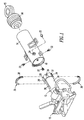
- a coupler head 10 and a shank portion 12 of the coupler head 10 are illustrated ready for assembly with a draft gear tube 14.
- the assembly preferably, is mechanically connected to the underside of a vehicle (not shown) via a circular bushing 15.
- Such circular bushing 15 is, also, connected to an energy absorbing and dissipating means 16.
- Such energy absorbing and dissipating means 16 is disposed for containment within the draft gear tube 14.
- the draft gear tube 14 has, in addition, a threaded mouth portion 18 located at the forward end of such draft gear tube 14 for the purposes to be discussed in more detail hereinafter.
- Shank portion 12 is a substantially hollow tube-like structure that is provided as an integral part of such coupler head 10.
- the shank portion 12 extends rearwardly from the coupler head 10 and is sized to fit into such draft gear tube 14.
- An integral collar member 20 is located at the distant end of the shank portion 12, i.e., at the end of the shank portion 12 that is remote from the structure of the coupler head 10.
- the integral collar member 20 is, also, sized to fit and extend into such draft gear tube 14 and to engage the inside surface of the draft gear tube 14 when a plurality of radially extending shear bolts 22 are threaded into and through threaded openings 24 provided in such draft gear tube 14 and into threaded holes 26 provided in such integral collar member 20, in a manner presently to be explained.
- shank portion 12 and integral collar member 20 are provided with at least two longitudinally extending slots 28.
- These longitudinally extending slots 28, preferably, form two resilient, flexible spring-like circular wall portions 30 and two circular collar sections 32.
- such longitudinally extending slots 28 are shown diametrically opposed so that the circular wall portions 30 are the same size and, also, diametrically opposed.
- the number of longitudinally extending slots 28 and circular wall portions 30 are chosen to maintain the strength and integrity of the shank portion 12 and integral collar member 20 while at the same time providing a spring-like resiliency to the circular wall portions 30.
- shear bolts 22 pull the distal ends of wall portions 30 of the shank portion 12 and the integral collar member 32 toward the inside surface of such draft gear tube 14. With continued rotation of shear bolts 22, the integral collar member 32 is drawn into contact with and engages the inside surface of the draft gear tube 14 thereby stabilizing the integral collar member 32 and shank portion 12 within draft gear tube 14 and placing the shear bolts 22 in a substantially pure shear mode.
- the pure shear mode of the shear bolts 22 is further assisted and assured by providing longitudinally extending relief grooves 34 in such integral collar member 20.
- Such longitudinally extending relief grooves 34 providing the integral collar member 20 with additional flexibility for disposition against the inside surface of the draft gear tube 14.
- the grooves 34 do not extend through the thickness dimension of the integral collar member 20, as is the case with the longitudinally extending slots 28.
- two grooves 34 are shown diametrically opposed to each other and are located between the longitudinally extending slots 28 at generally equal circumferential distances and angles from such longitudinally extending slots 28.
- a two piece ring or bushing 36 is disposed and secured together about the shank portion 12 and at a location between the integral collar member 32 and such coupling head 10.
- the outside peripheral surfaces of the two pieces of such ring 36 are threaded at 38 and are sized for threading into the threaded mouth 18 of such draft gear tube 14 when the two pieces of the ring 36 are secured together.
- ring 36 The purpose of ring 36 is to keep the shank portion 12 in the draft gear tube 14 after the shear bolts 22 are sheared from the shank portion 12. This is effected in the present invention by the integral collar member 32 abutting again the ring 36. This allows the vehicle containing the apparatus of the invention to be towed after such shear bolts 22 are sheared in two, because the shank portion 12 will be prevented from being pulled from such draft gear tube 14 by the ring 36.
- the vehicle can be towed to a repair shop, for example, for refitting the apparatus of Figure 1 with new shear bolts 22.
- the "stub" ends of broken bolts can be removed by hand or by an "easy out” thread extractor. Tapped holes are not damaged when the bolts break so that there is no need to re-tap. In other words, the holes do not need to be retapped for receiving new shear bolts 22.
- the threaded ring 36 disposed in the threaded mouth 18 of the draft gear tube 14 permits the ring 36 to be unscrewed from such draft gear tube 14 by use of a peg spanner wrench that engage holes provided in the ring 36. This allows the shank portion 12 and such integral collar member 32 to be removed from the draft gear tube 14 for repair purposes.
Landscapes
- Engineering & Computer Science (AREA)
- Mechanical Engineering (AREA)
- Gears, Cams (AREA)
- Shafts, Cranks, Connecting Bars, And Related Bearings (AREA)
- Mechanical Operated Clutches (AREA)
Claims (9)
- den Kupplungsstoß aufnehmende Kupplung, wobei die Kupplung umfasst:(a) ein im Wesentlichen hohles Zugschlepprohr (14) mit einer inneren Fläche;(b) einen Kupplungskopf (10) mit einem im Wesentlichen hohlen Schaftteil (12), wobei sich ein entferntes Ende des im Wesentlichen hohlen Schaftteils (12) in ein Ende des im Wesentlichen hohlen Zugschlepprohres (14) erstreckt;(c) wobei das im Wesentlichen hohle Schaftteil (12) in Längsrichtung geschlitzt (28) ist, in einer Weise, die es dem entfernten Ende davon ermöglicht, mit einer inneren Fläche des Zugschlepprohrs (14) in Eingriff zu kommen; und(d) eine vorgegebene Anzahl von radial ausgerichteten Scherbolzen (22), die durch das Zugschlepprohr und in das im Wesentlichen hohle Schaftteil geschraubt werden, in einer Weise, das den im Wesentlichen hohlen Schaftteil an der Innenfläche des Zugschlepprohrs sichert.
- Kupplungsstoß aufnehmende Kupplung nach Anspruch 1, wobei der im Wesentlichen hohle Schaftteil (12) des Kupplungskopfes (10) flexibel ist.
- Kupplungsstoß aufnehmende Kupplung nach Anspruch 2, wobei das entfernte Ende des im Wesentlichen hohlen Schaftteils (12) eine Manschette (32) enthält.
- Kupplungsstoß aufnehmende Kupplung nach Anspruch 3, wobei die Manschette (32) Längsschlitze (28) enthält, die es ihr ermöglichen, sich auszudehnen und mit der Innenfläche des Zugschlepprohrs in Eingriff zu kommen, wenn die Scherbolzen (22) in die Manschette eingeschraubt werden.
- Kupplungsstoß aufnehmende Kupplung nach Anspruch 3, wobei die Manschette (32) eine vorgegebene Anzahl von darin angeordneten, sich in Längsrichtung erstreckenden Entlastungsnuten (34) enthält.
- Kupplungsstoß aufnehmende Kupplung nach Anspruch 3, wobei die Manschette (32) ein einstückig ausgebildetes Teil des entfernten Endes des im Wesentlichen hohlen Schaftteils (12) ist.
- Kupplungsstoß aufnehmende Kupplung nach Anspruch 3, wobei die Kupplung ferner eine Einrichtung (36) enthält, die an der inneren Fläche des Zugschlepprohrs (14) an einer Stette hinter der Manschette (32) angeordnet ist, um zu verhindern, dass die Kupplung vom Zugschlepprohr gezogen wird, wenn ein die Kupplung enthaltendes Fahrzeug abgeschleppt wird, nachdem die Scherbolzen gebrochen sind.
- Kupplungsstoß aufnehmende Kupplung nach Anspruch 7, wobei die Einrichtung zum Verhindern des Abziehens der Kupplung von dem Zugschlepprohr (14) mindestens eins von einem Ring und einer Buchse (36) ist, die in das Zugschlepprohr geschraubt wird.
- Kupplungsstoß aufnehmende Kupplung nach Anspruch 8, wobei die Einrichtung zum Verhindern des Abziehens der Kupplung von dem Zugschlepprohr (14) ein Ring (36) ist, der in das Zugschlepprohr geschraubt wird.
Applications Claiming Priority (2)
| Application Number | Priority Date | Filing Date | Title |
|---|---|---|---|
| US09/512,487 US6321922B1 (en) | 2000-02-24 | 2000-02-24 | Coupling shock resistant (csr) coupler |
| US512487 | 2000-02-24 |
Publications (3)
| Publication Number | Publication Date |
|---|---|
| EP1127769A2 EP1127769A2 (de) | 2001-08-29 |
| EP1127769A3 EP1127769A3 (de) | 2002-09-18 |
| EP1127769B1 true EP1127769B1 (de) | 2003-11-05 |
Family
ID=24039309
Family Applications (1)
| Application Number | Title | Priority Date | Filing Date |
|---|---|---|---|
| EP01102484A Expired - Lifetime EP1127769B1 (de) | 2000-02-24 | 2001-02-05 | Den Kupplungsstoss aufnehmende Kupplung |
Country Status (5)
| Country | Link |
|---|---|
| US (1) | US6321922B1 (de) |
| EP (1) | EP1127769B1 (de) |
| AU (1) | AU773703B2 (de) |
| CA (1) | CA2326593C (de) |
| DE (1) | DE60101103T2 (de) |
Families Citing this family (7)
| Publication number | Priority date | Publication date | Assignee | Title |
|---|---|---|---|---|
| US6981599B2 (en) * | 2003-08-08 | 2006-01-03 | Westinghouse Air Brake Technologies Corporation | High capacity shear mechanism |
| ES2290817T3 (es) | 2005-05-06 | 2008-02-16 | VOITH TURBO SCHARFENBERG GMBH & CO. KG | Enganche separable de posicion central. |
| US7766177B2 (en) * | 2006-12-08 | 2010-08-03 | Wabtec Holding Corp. | Fatigue-resistant emergency release device for rail transit vehicle coupler |
| CN102582647A (zh) * | 2012-03-29 | 2012-07-18 | 王树银 | 一种铁路车辆救援车钩 |
| US9701323B2 (en) | 2015-04-06 | 2017-07-11 | Bedloe Industries Llc | Railcar coupler |
| RU2756118C1 (ru) | 2018-07-30 | 2021-09-28 | Сименс Мобилити Гмбх | Опора сцепки для средней буферной сцепки рельсового транспортного средства |
| SE547463C2 (en) * | 2024-02-26 | 2025-09-30 | Dellner Couplers Ab | Freight Coupler and Rail Vehicle |
Family Cites Families (8)
| Publication number | Priority date | Publication date | Assignee | Title |
|---|---|---|---|---|
| US1165190A (en) * | 1915-03-05 | 1915-12-21 | Alvin C Mccord | Coupling draw-bar. |
| US3118692A (en) * | 1959-07-30 | 1964-01-21 | Nelson S Fitzhugh | Plastic hose coupling |
| US3968982A (en) * | 1973-09-19 | 1976-07-13 | Siemens Aktiengesellschaft | Coaxial metallurgical connection |
| US4022329A (en) * | 1976-01-16 | 1977-05-10 | Dresser Industries, Inc. | Draft rigging for railway cars |
| US4017139A (en) * | 1976-06-04 | 1977-04-12 | Sealectro Corporation | Positive locking electrical connector |
| US4178023A (en) * | 1977-02-09 | 1979-12-11 | Guest John D | Couplings for tubes |
| US4346795A (en) * | 1980-06-23 | 1982-08-31 | Harvey Hubbell Incorporated | Energy absorbing assembly |
| FR2777251B1 (fr) * | 1998-04-14 | 2000-12-22 | Nantes Ecole Centrale | Dispositif absorbeur de chocs pour tampon amortisseur de vehicules ferroviaires ou autres |
-
2000
- 2000-02-24 US US09/512,487 patent/US6321922B1/en not_active Expired - Lifetime
- 2000-11-23 CA CA002326593A patent/CA2326593C/en not_active Expired - Fee Related
-
2001
- 2001-01-24 AU AU16433/01A patent/AU773703B2/en not_active Ceased
- 2001-02-05 EP EP01102484A patent/EP1127769B1/de not_active Expired - Lifetime
- 2001-02-05 DE DE60101103T patent/DE60101103T2/de not_active Expired - Fee Related
Also Published As
| Publication number | Publication date |
|---|---|
| EP1127769A2 (de) | 2001-08-29 |
| CA2326593C (en) | 2004-11-16 |
| AU1643301A (en) | 2001-08-30 |
| AU773703B2 (en) | 2004-06-03 |
| CA2326593A1 (en) | 2001-08-24 |
| US6321922B1 (en) | 2001-11-27 |
| DE60101103T2 (de) | 2004-08-26 |
| EP1127769A3 (de) | 2002-09-18 |
| DE60101103D1 (de) | 2003-12-11 |
Similar Documents
| Publication | Publication Date | Title |
|---|---|---|
| RU2342272C2 (ru) | Муфтовое соединительное устройство для сцепок транспортных средств | |
| US10807618B2 (en) | Assembly with a bearing bracket and a coupler rod or a connection rod; car of a multi-car vehicle and method for transmitting pushing forces applied to a coupler rod or connection rod to a bearing bracket | |
| EP1127769B1 (de) | Den Kupplungsstoss aufnehmende Kupplung | |
| US2802580A (en) | Car couplers | |
| CA2121872C (en) | Slackless buff gear connection system | |
| TWI385089B (zh) | 用於鐵路運輸載具耦合器之抗疲勞性緊急釋放裝置 | |
| CA2317078C (en) | Coupler with extended emergency release and towing feature | |
| CA2605513A1 (en) | Two piece draft gear housing having an integral yoke | |
| US2635766A (en) | Railway draft gear cushioning mechanism | |
| WO2025180668A1 (en) | Freight coupler and rail vehicle | |
| EP0751055B1 (de) | Spielfreie Zugstangenanordnung für einen Güterwagon | |
| RU2729117C2 (ru) | Энергопоглощающий крепежный элемент, шарнирное крепление и вагон | |
| US3610434A (en) | Emergency release coupler | |
| US9283970B2 (en) | Drive arrangement for a running gear | |
| KR102141113B1 (ko) | 철도차량 연결기용 충격흡수장치 | |
| US3247977A (en) | Railway draft rigging | |
| RU2137631C1 (ru) | Устройство для снятия поглощающего аппарата с тяговым хомутом сцепного устройства | |
| US5092204A (en) | Apparatus for aligning spherical member during assembly of an articulated coupling system | |
| CN111601748A (zh) | 轨道车转向架承梁 | |
| US20230093266A1 (en) | Drawbar for vehicle coupler | |
| US5394998A (en) | Front draft stop for use in a drawbar assembly | |
| WO2025239785A1 (en) | A coupler assembly for coupling railway wagons | |
| CN110621565A (zh) | 适合用作连接多车厢车辆中的第一车厢和多车厢车辆中的第二车厢的连接装置的一部分的消能装置以及用于在连接装置中消散能量的方法 | |
| AU2003200763A1 (en) | Couplings for trains |
Legal Events
| Date | Code | Title | Description |
|---|---|---|---|
| PUAI | Public reference made under article 153(3) epc to a published international application that has entered the european phase |
Free format text: ORIGINAL CODE: 0009012 |
|
| AK | Designated contracting states |
Kind code of ref document: A2 Designated state(s): AT BE CH CY DE DK ES FI FR GB GR IE IT LI LU MC NL PT SE TR |
|
| AX | Request for extension of the european patent |
Free format text: AL;LT;LV;MK;RO;SI |
|
| PUAL | Search report despatched |
Free format text: ORIGINAL CODE: 0009013 |
|
| AK | Designated contracting states |
Kind code of ref document: A3 Designated state(s): AT BE CH CY DE DK ES FI FR GB GR IE IT LI LU MC NL PT SE TR |
|
| AX | Request for extension of the european patent |
Free format text: AL;LT;LV;MK;RO;SI |
|
| 17P | Request for examination filed |
Effective date: 20021121 |
|
| GRAH | Despatch of communication of intention to grant a patent |
Free format text: ORIGINAL CODE: EPIDOS IGRA |
|
| AKX | Designation fees paid |
Designated state(s): DE FR GB IT |
|
| GRAS | Grant fee paid |
Free format text: ORIGINAL CODE: EPIDOSNIGR3 |
|
| GRAA | (expected) grant |
Free format text: ORIGINAL CODE: 0009210 |
|
| AK | Designated contracting states |
Kind code of ref document: B1 Designated state(s): DE FR GB IT |
|
| REG | Reference to a national code |
Ref country code: GB Ref legal event code: FG4D |
|
| REF | Corresponds to: |
Ref document number: 60101103 Country of ref document: DE Date of ref document: 20031211 Kind code of ref document: P |
|
| REG | Reference to a national code |
Ref country code: IE Ref legal event code: FG4D |
|
| PGFP | Annual fee paid to national office [announced via postgrant information from national office to epo] |
Ref country code: FR Payment date: 20040219 Year of fee payment: 4 |
|
| PGFP | Annual fee paid to national office [announced via postgrant information from national office to epo] |
Ref country code: DE Payment date: 20040331 Year of fee payment: 4 |
|
| ET | Fr: translation filed | ||
| PLBE | No opposition filed within time limit |
Free format text: ORIGINAL CODE: 0009261 |
|
| STAA | Information on the status of an ep patent application or granted ep patent |
Free format text: STATUS: NO OPPOSITION FILED WITHIN TIME LIMIT |
|
| 26N | No opposition filed |
Effective date: 20040806 |
|
| REG | Reference to a national code |
Ref country code: IE Ref legal event code: MM4A |
|
| PG25 | Lapsed in a contracting state [announced via postgrant information from national office to epo] |
Ref country code: IT Free format text: LAPSE BECAUSE OF NON-PAYMENT OF DUE FEES Effective date: 20050205 Ref country code: GB Free format text: LAPSE BECAUSE OF NON-PAYMENT OF DUE FEES Effective date: 20050205 |
|
| PG25 | Lapsed in a contracting state [announced via postgrant information from national office to epo] |
Ref country code: DE Free format text: LAPSE BECAUSE OF NON-PAYMENT OF DUE FEES Effective date: 20050901 |
|
| GBPC | Gb: european patent ceased through non-payment of renewal fee |
Effective date: 20050210 |
|
| PG25 | Lapsed in a contracting state [announced via postgrant information from national office to epo] |
Ref country code: FR Free format text: LAPSE BECAUSE OF NON-PAYMENT OF DUE FEES Effective date: 20051031 |
|
| REG | Reference to a national code |
Ref country code: FR Ref legal event code: ST Effective date: 20051031 |