EP1127786B1 - Pale de rotor pour hélicoptère - Google Patents
Pale de rotor pour hélicoptère Download PDFInfo
- Publication number
- EP1127786B1 EP1127786B1 EP01301667A EP01301667A EP1127786B1 EP 1127786 B1 EP1127786 B1 EP 1127786B1 EP 01301667 A EP01301667 A EP 01301667A EP 01301667 A EP01301667 A EP 01301667A EP 1127786 B1 EP1127786 B1 EP 1127786B1
- Authority
- EP
- European Patent Office
- Prior art keywords
- wing
- tip
- rotor blade
- base
- chord length
- Prior art date
- Legal status (The legal status is an assumption and is not a legal conclusion. Google has not performed a legal analysis and makes no representation as to the accuracy of the status listed.)
- Expired - Lifetime
Links
- 230000003993 interaction Effects 0.000 description 9
- 238000010586 diagram Methods 0.000 description 7
- 230000000694 effects Effects 0.000 description 6
- 238000009792 diffusion process Methods 0.000 description 5
- 238000002474 experimental method Methods 0.000 description 5
- 230000035939 shock Effects 0.000 description 4
- 239000013598 vector Substances 0.000 description 4
- 238000013016 damping Methods 0.000 description 2
- 230000007423 decrease Effects 0.000 description 2
- 238000010276 construction Methods 0.000 description 1
- 238000011835 investigation Methods 0.000 description 1
- 238000000034 method Methods 0.000 description 1
Images


Classifications
-
- B—PERFORMING OPERATIONS; TRANSPORTING
- B64—AIRCRAFT; AVIATION; COSMONAUTICS
- B64C—AEROPLANES; HELICOPTERS
- B64C27/00—Rotorcraft; Rotors peculiar thereto
- B64C27/32—Rotors
- B64C27/46—Blades
- B64C27/463—Blade tips
Definitions
- the present invention relates to a rotor of a helicopter and, more particularly, to a rotor blade of a helicopter which produces reduced noise.
- the blade of the rotor interacts with the tip vortex, as generated from the tip of the advancing rotor blade, to generate BVI (blade vortex interaction) noises. It is known that the magnitude of the BVI noises depends upon the planar shape of the tip of the rotor blade which generates the tip vortex.
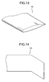
- a rotor 100 of a helicopter is known as shown in Fig. 12 , with a plurality of rotor blades 101, each of which has a generally rectangular shape, as its tip is shown in Fig. 13 , for example, and which rotate on the center of rotation 102.
- the tip trailing edge vortex 103 As generated at the tip of an advancing rotor blade 101a, does not quickly fall so that a retreating rotor blade 101b interacts with the tip trailing edge vortex 103 generated at the tip of the rotor blade 101a, thereby to cause the BVI noises.
- the tip vortex to be generated is halved and weakened by mounting a small wing 105 having a rectangular shape to the leading edge of the rectangular tip of the rotor blade 101, so that the BVI noises can be lowered.
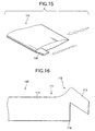
- a rotor blade 110 as disclosed in Unexamined Published Japanese Patent Application No. 4-262994 , is provided with a leading blade 115 merging into a base wing 113 of an airfoil section having a leading edge 112, as shown in a top plan shape of a tip portion 111 in Fig. 16 .
- the vortex emanating from the rotor blade 110 is halved into tip vortexes of substantially equal intensities, i.e., a vortex 115a emanating from the leading blade 115 and as vortex 116a emanating from a trailing wing 116, as located on the inner side of the leading wing 115, thereby to reduce the BVI noises.
- the aforementioned rotor blade 110 of Unexamined Published Japanese Patent Application No. 4-262994 suppresses the influences of the BVI by making a division into the two vortexes of substantially equal intensities, that is, the vortex 115a emanating from the leading wing 115 and the vortex 116a emanating from the trailing wing 116.
- This construction is characterized in that the span of the leading wing 115 is made larger by 50 % or more than the chord length of the base wing 113 by generating the two vortexes of substantially equal intensities to hold these vortexes in the separate state as long as possible.
- the effect of the interactions of the vortexes is weak, and the leading wing 115 is made slender thereby to make it necessary to enhance especially the strength of the root portion of the leading wing 115.
- US-A-4,046,336 discloses vortex diffusion means for an aircraft having lift structure rooted therein that extends outboard to a structure tip from which a discrete tip vortex develops when said tip is propelled through the air.
- a sub-wing extends from the tip of the lift structure.
- the sub-wing has its leading edge or upper lead surface tangent to the upper lead surface of the lift structure and a span axis parallel to the span axis of the lift structure.
- the sub-wing's chord is sized to equally divide the bound vorticity shed at the tip of the lift structure so that twin discrete vortices are generated.
- One discrete vortex forms along the streamwise edge of the lift structure's tip and the other forms along the streamwise edge of the sub-wing's tip.
- the distance between the two vortices is in the range of from 25 to 50% of the local chord of the lift structure.
- the invention has been conceived in view of those points and has an object to provide a rotor blade of a helicopter, which is intended to reduce the noises by dividing the tip vortex, as might otherwise cause the BVI noises of the helicopter, and by causing the divided tip vortexes to interact positively with each other thereby to diffuse them.
- a rotor blade for a helicopter which is attached at root portion thereof to a rotor head of a rotational drive unit, the rotor blade comprising:
- the vortex generated at the wing tip is divided into a plurality of relatively weak tip vortexes generated at the tips of the individual small wings, and the individual small wings have equal spans. Therefore, the vortexes generated at the tips of the individual small wings are close to each other and interfere positively with each other and are weakened and diffused. As a result, when the helicopter is to land, the pressure fluctuations, as might otherwise be caused by the interactions between the retreating rotor blade and the tip vortexes generated as the tip of the advancing rotor blade, are drastically reduced to suppress the occurrence of the BVI noises.
- the present invention restricts the small wings of the invention specifically to the front wing and the rear wing.
- the vortex generated at the wing tip is divided into the two vortexes, i.e., the front wing vortex generated at the tip of the front wing and the rear wing vortex generated at the tip of the rear wing.
- the front wing vortex generated at the front wing moves over the rear wing backward of the rear wing, and the rear wing vortex generated at the tip of the rear wing also moves backward so that the front wing vortex and the rear wing vortex interact positively with each other and are weakened and diffused to suppress the occurrence of the BVI noises.
- said base wing has a rectangular tip shape; said front wing has a chord length of about 20% to 30% of the chord length of said base wing; said rear wing has a chord length of about 30% to 50% of the chord length of said base wing; and said front wing and said rear wing have substantially equal spans of about 20 to 30% of the chord length of said base wing and are spaced by about 20% to 50% of the chord length of said base wing.
- the front wing and the rear wing having a rectangular shape are arranged at the base wing having a rectangular tip shape, so that the front wing vortex and the rear wing vortex are efficiently caused to interact with each other and are diffused by setting the chord lengths and the spans of the front wing and the rear wing and the spacing between the front wing and the rear wing to the above-specified ranges.
- the front wing and the rear wing have an anhedral angle of about 10 degrees to 30 degrees.
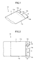
- FIG. 1 is a perspective view showing the tip of a rotor blade 10 of a helicopter according to this embodiment
- Fig. 2 is a top plan view of Fig. 1 .
- a plurality of rotor blades 10, as shown in Figs. 1 and 2 is attached to a (not shown) rotor hub to form a rotor.
- the rotor blade 10 is provided with a base wing 11 having a substantially equal chord length and a rectangular tip shape, and a smaller front wing 12 and a larger rear wing 13 disposed along its chord at the tip of the base wing 11.
- the front wing 12 merges at its leading edge 12a into the leading edge 11a of the base wing 11 and is formed into a rectangular shape having a chord length c1 of 20 to 30% of the chord length c of the base wing 11 and a span b1 of 20 % to 30 % of the chord length c of the base wing 11.
- the rear wing 13 merges at its trailing edge 13b into the trailing edge 11b of the base wing 11 and is formed into a rectangular shape having a chord length c2 of 30 % to 50 % of the chord length c of the base wing 11 and larger than the chord length c1 of the front wing 12 and a span b2 of 20 % to 30 % of the chord length c of the base wing 11 and substantially equal to the span b1 of the front wing 12.
- the trailing edge 12b of the front wing 12 and the leading edge 13a of the rear wing 13 are spaced by about 20% to 50 % of the chord length c of the base wing 11.
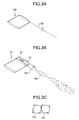
- the tip vortex diffusion will be compared between the tip of the rotor blade 10 thus formed and the conventional rectangular tip with reference to explanatory diagrams shown in Fig. 3A to 3C .
- a conventional rotor blade 120 as shown in Fig. 3A , an intense tip vortex 12a is generated at the tip and is carried backward without being diffused.
- the vortex to be generated at the tip is divided into two relatively weak vortexes: a front wing vortex 12c generated at the tip of the front wing 12 and a rear wing vortex 13c generated at the tip of the rear wing 13.
- the front wing vortex 12c at the front wing moves over the rear wing 13 and backward over the vicinity of the root portion of the rear wing 13.
- the rear wing vortex 13c generated at the tip of the rear wing 13 also moves backward.
- the front wing 12 and the rear wing 13 have substantially equal spans b1 and b2.
- the front wing vortex 12c at the tip of the front wing 12 and the rear wing vortex 13c at the tip of the rear wing 13 are close to each other so that they positively interact with one other and are weakened and diffused, as illustrated in a rear elevation in Fig. 3C by the front wing vortex 12c and the rear wing vortex 13c.
- the vortexes to leave the rotor blade 10 are diffused and weakened so that the pressure fluctuations to be caused by the interactions between the tip vortexes generated at the tips of the retreating rotor blade 10 and the advancing rotor blade 10 of the rotor when the helicopter is to land, for example, are drastically reduced to suppress the occurrence of the BVI noises.
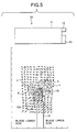
- Figs. 4 and 5 illustrate vorticity contour lines h and slip flow velocity vectors v, as taken at a wind speed of 40 m/s and at an angle of incidence of 10 degrees, at positions which are located backward by one chord length from the individual trailing edges of the rotor blade 120 having the rectangular tip and the rotor blade 10 of this embodiment.
- the density of the vorticity contour lines h is thin, and as the magnitude of the slip flow velocity vectors is smaller, the vortex diffusion is improved thereby to lower the level of the BVI noises.
- Fig. 6 illustrates the vorticity contour lines h and the slip flow velocity vectors v, as taken at the wind speed of 40 m/s and at the incidence angle of 10 degrees, at positions located backward by one chord length from the trailing edge of a rotor blade 125 of this embodiment, in which the span b2 of the rear wing 13 is made longer than the span b1 of the front wing 12.
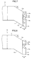
- Fig. 7 is a top plan view showing the tip of the rotor blade 10 corresponding to that of the first embodiment of Fig. 2 , as will be described mainly on different portions by designating the corresponding portions by the common reference numerals to omit their detailed descriptions.
- the base wing 11 of the rotor blade 10 has a generally equal chord length c and is formed into a sweepback tip shape having a sweepback angle ⁇ of 20 degrees to 40 degrees.
- the front wing 12 is provided with the leading edge 12a and the trailing edge 12b having a sweepback angle ⁇ of 20 degrees to 40 degrees and is formed to have the chord length c1 of 20 % to 30 % of the chord length c of the base wing 11 and the span b1 of 20 % to 30 % of the chord length c of the base wing 11.
- the rear wing 13 is provided with the leading edge 13a and the trailing edge 13b having a sweepback angle ⁇ of 20 degrees to 40 degrees and has a chord length c2 of 30% to 50%, preferably of 30% to 40%, of the chord length c of the base wing 11 and larger than the chord length c1 of the front wing 12 and a span b2 of 20 % to 30 % of the chord length c of the base wing 11 and substantially equal to the span b1 of the front wing 12.
- the trailing edge 12b of the front wing 12 and the leading edge 13a of the rear wing 13 is spaced by about 20 % to 50 % of the chord length c of the base wing 11.
- the base wing 11, the front wing 12 and the rear wing 13 have the sweepback angle ⁇ .
- the airspeed of the wing tip is lowered to damp the compressibility of the air and weaken the shock waves thereby to improve the transonic characteristics.
- Fig. 8 is a top plan view showing the tip of the rotor blade 10 corresponding to that of the aforementioned second embodiment, as will be described mainly on different portions by designating the corresponding portions by the common reference numerals to omit their detailed descriptions.
- the base wing 11 of the rotor blade 10 has a generally equal chord length c and is formed into a sweepback tip shape having a sweepback angle A of 20 degrees to 40 degrees.
- the front wing 12 is provided with the leading edge 12a having a root portion chord length of about 20 % to 30 % of the chord length of the base wing 11 and a sweepback angle ⁇ of 20 to 40 degrees and is formed into a tapered wing shape having a span b1 of 20 to 30 % of the chord length c of the base wing 11 and a smooth taper ratio of 0.8 or less from the root portion to the tip.
- the rear wing 13 is provided with the leading edge 13a having a root portion chord length of about 30% to 50%, preferably 30% to 40%, of the chord length of the base wing 11 and a sweepback angle ⁇ of 20 degrees to 40 degrees and is formed into a tapered wing shape having a chord length of 30% to 40 % of the chord length c of the base wing 11, a span b2 substantially equal to the span b1 of the front wing 12, and and a smooth taper ratio of 0.8 or less from the root portion to the tip.
- the base wing 11, the front wing 12 and the rear wing 13 have tapered shapes.
- the lift distribution at the wing tip is reduced to improve the damping effect of the tip vortex.
- Fig. 9A and 9B present explanatory diagrams of a rotor blade 10 according to this embodiment.
- Fig. 9A is a top plan view of the tip of the rotor blade 10 corresponding to Fig. 2 of the foregoing first embodiment
- Fig. 9B is a side elevation of Fig. 9A .
- this embodiment will be described mainly on different portions by designating the corresponding portions by the common reference numerals to omit their detailed descriptions.
- the rotor blade 10 is provided with the base wing 11 having a substantially equal chord length c and formed into a rectangular tip shape.
- the base wing 11 having a substantially equal chord length c and formed into a rectangular tip shape.
- the front wing 12 having a chord length c1 of 20 % to 30 % of the chord length c of the base wing 11 and a span b1 of 20 % to 30 % of the chord length c of the base wing 11
- the rear wing 13 having a chord length c2 of 30 % to 50 % of the chord length c of the base wing 11 and a span b2 substantially equal to the span b1 of the front wing 12.
- These front wing 12 and rear wing 13 have an anhedral angle ⁇ of 10 degrees to 30 degrees, as shown in Fig. 9B .
- the front wing 12 and the rear wing 13 have the anhedral angle ⁇ . Since the release position of the tip vortex is lowered, therefore, the tip vortex, as generated at the tip of the rotor blade while the helicopter is hovering or when the helicopter is to land, is positively released downward to avoid the interactions between the tip vortex generated by the advancing rotor blade and the retreating rotor blade thereby to reduce the torque necessary for the rotation.
- Fig. 10 is a top plan view of the tip of a rotor blade 10 according to this embodiment.
- this embodiment will be described mainly on different portions by designating the portions corresponding to those of Fig. 2 in the foregoing first embodiment by the common reference numerals to omit their detailed descriptions.
- the rotor blade 10 is provided with a base wing 11 of a rectangular tip shape having a chord length c, a front wing 12 and a rear wing 13 disposed at the tip of the base wing 11, and an intermediate wing 14 between the front wing 12 and the rear wing 13.
- the front wing 12, the rear wing 13 and the intermediate wing 14 are formed to have individual chord lengths c1, c2 and c3 of 20% to 30%, preferably about 25%, of the chord length c of the base wing 11 and individual spans b1, b2 and b3 substantially equal to one another and 20 % to 30 % of the chord length c of the base wing 11.
- the trailing edge 12b of the front wing 12 and the leading edge 14a of the intermediate wing 14, and the trailing edge 14b of the intermediate wing 14 and the leading edge 13a of the rear wing 13 are individually spaced from each other by 10% to 15%, preferably about 12%, of the chord length c of the base wing 11.
- the vortex to occur at the tip is divided into three weak rear wing vortexes to occur at the individual tips of the front wing 12, the intermediate wing 14 and the rear wing 13, and these rear wing vortexes interact and are diffused more effectively.
- the pressure fluctuations, as caused by the interactions between the retreating rotor blade 10 of the rotor and the tip vortex to occur at the tip of the advancing rotor blade 10 are drastically reduced to further suppress the occurrence of BVI noises.
- the rectangular tip of the base wing 11 is provided with the three small wings of the front wing 12, the rear wing 13 and the intermediate wing 14, but could be equipped with four or more small wings, if necessary.
- the front wing, the rear wing and the intermediate wing having the sweepback angle could be arranged at the sweepback base wing 11 having the sweepback angle ⁇ , as in the second embodiment.
- the front wing, the rear wing and the intermediate wing could be tapered, as in the fourth embodiment, and these small wings could also be given the anhedral angle, as in the fourth embodiment.
- Fig. 11 is a perspective view of an essential portion of a rotor blade 10 according to this embodiment.
- this embodiment will be described mainly on different portions by designating the portions corresponding to those of Fig. 2 in the foregoing first embodiment by the common reference numerals to omit their detailed descriptions.
- the rotor blade 10 is provided with a base wing 11 having a rectangular tip shape, and a front wing 12 and a rear wing 13 arranged at the tip of the base wing 11.
- the front wing 12 is formed to have a chord length of 20 % to 30 % of the chord length of the base wing 11 and a span of 20 % to 30 % of the chord length of the base wing 11, and is variably controlled at its incidence angle by variable control unit 31.
- the rear wing 13 is formed to have a chord length c of 30 % to 50 % of the chord length of the base wing 11 and a span substantially equal to the span of the front wing 12, and is variably controlled at its incidence angle by variable control unit 35.
- the variable control unit 31 is provided with an actuator such as a servomotor or a hydraulic actuator, as exemplified by the servomotor 32 in this embodiment, and a shaft 33 protruding from the servomotor 32 and supporting the front wing 12 at the tip of the base wing 11.
- an actuator such as a servomotor or a hydraulic actuator, as exemplified by the servomotor 32 in this embodiment, and a shaft 33 protruding from the servomotor 32 and supporting the front wing 12 at the tip of the base wing 11.
- variable control unit 35 is provided with an actuator such as a servomotor or a hydraulic actuator, as exemplified by the servomotor 36 in this embodiment, and a shaft 37 protruding from the servomotor 36 and supporting the rear wing 13 at the tip of the base wing 11.
- actuator such as a servomotor or a hydraulic actuator
- shaft 37 protruding from the servomotor 36 and supporting the rear wing 13 at the tip of the base wing 11.
- reference numerals 32a and 32b, and 36a and 36b designate power supply and signal cables to the servomotors 32 and 36, respectively.
- the airspeed is added at the advancing rotor blade to the rotor blade speed, whereas the airspeed is subtracted at the retreating rotor blade from the rotor blade speed.
- the airspeed is so different between the advancing rotor blade and the retreating rotor blade that the advancing rotor blade is demanded for a lower drag in the transonic region because of its higher Mach number and smaller incidence angle whereas the retreating rotor blade is demanded for a reluctant stall in the subsonic region because of its lower Mach number and larger incidence angle.
- the individual incidence angles of the front wing 12 and the rear wing 13 are variably controlled by the servomotors 32 and 36 so that the front wing vortex generated at the tip of the front wing 12 and the rear wing vortex generated at the tip of the rear wing 13 can be efficiently caused to interact and diffused while avoiding the influences of the stall or the drag divergence.
- variable control units 31 and 35 for controlling the incidence angles of the front wing 12 and the rear wing 13 variably, respectively.
- the invention should not be limited to the foregoing embodiments but could be variously modified without departing from the gist thereof.
- the incidence angle of the front wing and the rear wing having the sweepback angle could be arranged in a controllable manner, as in the sixth embodiment, and the incidence angle of the tapered front and rear wings could be controlled, as in the fourth embodiment.
- these small wings having the controllable incidence angle could be given the anhedral angle, as in the fourth embodiment.
- an intermediate wing could be arranged between the front wing and the rear wing.
- the base wing as attached at its root end portion to the rotor head of the rotational drive unit, is provided at its tip with the plurality of small wings having the substantially equal spans.
- the vortex generated at the wing tip is divided into the plurality of relatively weak tip vortexes generated at the tips of the individual small wings, and the tip vortexes generated at the wing tips of the individual small wings are so close that they positively interact with one another and are weakened and diffused.
- the pressure fluctuations to be caused by the interactions between the tip vortexes generated at the tips of the retreating rotor blade and the advancing rotor blade of the rotor are drastically reduced to suppress the occurrence of the BVI noises.
- the airspeed of the wing tip is lowered to damp the compressibility of the air and weaken the shock waves thereby to improve the transonic characteristics. Since the front wing and the rear wing are given the tapered shapes, on the other hand, the lift distribution at the wing tip is reduced to improve the damping effect of the tip vortex better.
- the tip vortex As generated at the tip of the rotor blade while the helicopter is hovering or when the helicopter is to land, is positively released downward to avoid the interactions between the tip vortex generated by the advancing rotor blade and the retreating rotor blade thereby to reduce the torque necessary for the rotation.
- the rear wing vortexes generated from the tips of the individual small wings can be efficiently caused to interact and diffused while avoiding the influences of the stall or the drag divergence.
Landscapes
- Engineering & Computer Science (AREA)
- Mechanical Engineering (AREA)
- Aviation & Aerospace Engineering (AREA)
- Structures Of Non-Positive Displacement Pumps (AREA)
- Turbine Rotor Nozzle Sealing (AREA)
- Toys (AREA)
Claims (3)
- Pale de rotor (10) pour un hélicoptère, pale qui est adaptée pour être attachée au niveau de la partie pied de celle-ci à une tête de rotor d'un module d'entraînement rotatif, la pale de rotor comportant :une voilure de base (11) qui est adaptée pour être attachée à ladite tête de rotor au niveau de la partie pied de celle-ci ; etun total de deux petites voilures (12, 13), chacune disposée au niveau de l'extrémité des ladite voilure de base (11), les deux petites voilures comportant :dans laquelle ladite voilure avant (12) et ladite voilure arrière (13) ont des formes rectangulaires et ont des envergures dans une large mesure égales ; etune voilure avant (12) ayant un bord d'attaque (12a) se fondant dans un bord d'attaque (11a) de ladite voilure de base ; etune voilure arrière (13) espacée dans la direction de la corde de ladite voilure de base (11) par rapport à ladite voilure avant (12) au niveau de l'extrémité de ladite voilure de base (11) et ayant un bord de fuite (13b) se fondant dans un bord de fuite (11b) de ladite voilure de base ;
dans laquelle ladite voilure avant (12) et ladite voilure arrière (13) ont le même dièdre négatif. - Pale de rotor selon la revendication 1, dans laquelle ladite voilure de base (11) a une forme d'extrémité rectangulaire ;
ladite voilure avant (12) a une longueur de corde (c1) d'environ 20 % à 30 % d'une longueur de corde (c) de ladite voilure de base (11);
ladite voilure arrière (13) a une longueur de corde (c2) d'environ 30 % à 50 % de la longueur de corde (c) de ladite voilure de base (11) ; et
ladite voilure avant (12) et ladite voilure arrière (13) ont des envergures dans une large mesure égales (b1, b2) d'environ 20 % à 30 % de la longueur de corde (c) de ladite voilure de base (11) et sont espacées d'environ 20 % à 50 % de la longueur de corde de ladite voilure de base. - Pale de rotor selon la revendication 1 ou la revendication 2, dans laquelle le dièdre négatif est d'environ 10 degrés à 30 degrés.
Applications Claiming Priority (2)
| Application Number | Priority Date | Filing Date | Title |
|---|---|---|---|
| JP2000045774A JP4535550B2 (ja) | 2000-02-23 | 2000-02-23 | 回転翼航空機の回転翼羽根 |
| JP2000045774 | 2000-02-23 |
Publications (2)
| Publication Number | Publication Date |
|---|---|
| EP1127786A1 EP1127786A1 (fr) | 2001-08-29 |
| EP1127786B1 true EP1127786B1 (fr) | 2008-08-06 |
Family
ID=18568308
Family Applications (1)
| Application Number | Title | Priority Date | Filing Date |
|---|---|---|---|
| EP01301667A Expired - Lifetime EP1127786B1 (fr) | 2000-02-23 | 2001-02-23 | Pale de rotor pour hélicoptère |
Country Status (4)
| Country | Link |
|---|---|
| US (1) | US6467732B2 (fr) |
| EP (1) | EP1127786B1 (fr) |
| JP (1) | JP4535550B2 (fr) |
| DE (1) | DE60135168D1 (fr) |
Families Citing this family (44)
| Publication number | Priority date | Publication date | Assignee | Title |
|---|---|---|---|---|
| FR2821605B1 (fr) * | 2001-03-01 | 2003-05-30 | Eads Airbus Sa | Procede et dispositif pour accelerer la destruction d'au moins deux vortex dans le sillage d'un mobile, en particulier d'un avion |
| US20050061921A1 (en) * | 2003-09-19 | 2005-03-24 | Egolf Thomas A. | Aerodynamic tip protuberances for tip vortex intensity reduction |
| JP2005335621A (ja) * | 2004-05-28 | 2005-12-08 | Fuji Heavy Ind Ltd | ヘリコプタのロータブレード |
| US7264200B2 (en) * | 2004-07-23 | 2007-09-04 | The Boeing Company | System and method for improved rotor tip performance |
| US7281900B2 (en) * | 2005-05-13 | 2007-10-16 | The Boeing Company | Cascade rotor blade for low noise |
| DE102006008434A1 (de) * | 2006-02-23 | 2007-09-06 | Airbus Deutschland Gmbh | Vorrichtung zur Reduzierung des aerodynamisch bedingten Lärms an der Seitenkante einer Stellfläche, insbesondere einer Hochauftriebsfläche eines Flugzeugs |
| GB0604026D0 (en) * | 2006-02-28 | 2006-04-12 | Airbus Uk Ltd | Aircraft wing |
| US7513750B2 (en) | 2006-03-08 | 2009-04-07 | Sikorsky Aircraft Corporation | Rotor blade tip planform |
| US20070262205A1 (en) * | 2006-05-09 | 2007-11-15 | Grant Roger H | Retractable multiple winglet |
| US8221363B2 (en) | 2006-10-18 | 2012-07-17 | Baxter Healthcare S.A. | Luer activated device with valve element under tension |
| US7981090B2 (en) | 2006-10-18 | 2011-07-19 | Baxter International Inc. | Luer activated device |
| US7753338B2 (en) | 2006-10-23 | 2010-07-13 | Baxter International Inc. | Luer activated device with minimal fluid displacement |
| US8083185B2 (en) * | 2007-11-07 | 2011-12-27 | The Boeing Company | Aircraft wing tip having a variable incidence angle |
| ES2363615B2 (es) * | 2008-02-28 | 2012-02-08 | Gamesa Innovation & Technology, S.L. | Pala para aerogeneradores |
| US9302766B2 (en) * | 2008-06-20 | 2016-04-05 | Aviation Partners, Inc. | Split blended winglet |
| GB2468903A (en) * | 2009-03-26 | 2010-09-29 | Ronald Denzil Pearson | Aerofoil tip vortex reducing structure |
| US20100135806A1 (en) * | 2009-06-22 | 2010-06-03 | General Electric Company | Hinged wind turbine blade tips |
| DE102009035689A1 (de) * | 2009-07-30 | 2011-02-03 | Eads Deutschland Gmbh | Fluiddynamisch wirksamer Rotor |
| KR101225701B1 (ko) * | 2010-10-22 | 2013-01-23 | 건국대학교 산학협력단 | 끝단의 와류 강도를 감소시킬 수 있는 회전익항공기용 회전익. |
| EP2450764B1 (fr) | 2010-11-05 | 2016-05-11 | Sikorsky Aircraft Corporation | Mise en oeuvre d'un estimateur de l'état linéaire d'un filtre Kalman pour l'égalisation de l'actionneur |
| US9132909B1 (en) * | 2011-03-11 | 2015-09-15 | The United States Of America As Represented By The Administrator Of The National Aeronautics And Space Administration | Flap edge noise reduction fins |
| US9227719B2 (en) * | 2011-03-11 | 2016-01-05 | The United States Of America As Represented By The Administrator Of The National Aeronautics And Space Administration | Reactive orthotropic lattice diffuser for noise reduction |
| DK3650337T3 (da) * | 2011-06-09 | 2021-02-22 | Aviation Partners Inc | Delt "blended" winglet |
| US8708286B2 (en) * | 2012-06-21 | 2014-04-29 | The Boeing Company | Swing tip assembly rotation joint |
| US9452825B2 (en) | 2013-04-19 | 2016-09-27 | The Boeing Company | Winglet attach fitting for attaching a split winglet to a wing |
| US10696387B2 (en) * | 2013-09-27 | 2020-06-30 | Dann M Allen | Helicopter rotor with a mechanical means for configuring rotor tips to control brown outs |
| GB2533413A (en) | 2014-12-19 | 2016-06-22 | Airbus Operations Ltd | Lifting Surfaces |
| JP6621585B2 (ja) * | 2015-02-27 | 2019-12-18 | 三菱重工業株式会社 | フラッタ制御装置 |
| CN205524939U (zh) * | 2016-01-27 | 2016-08-31 | 深圳市大疆创新科技有限公司 | 螺旋桨、动力组件及飞行器 |
| CN205366054U (zh) * | 2016-01-28 | 2016-07-06 | 深圳市大疆创新科技有限公司 | 螺旋桨、动力组件及飞行器 |
| EP3269635A1 (fr) | 2016-07-12 | 2018-01-17 | The Aircraft Performance Company UG | Aile d'avion |
| EP3293113B1 (fr) | 2016-09-07 | 2018-12-12 | LEONARDO S.p.A. | Rotor pour un avion capable de vol stationnaire et son procédé de commande |
| US10787251B2 (en) * | 2017-03-07 | 2020-09-29 | Textron Innovations Inc. | Variable sweep rotorcraft blade tip |
| RU2019144407A (ru) | 2017-07-12 | 2021-06-28 | Зе Эркрафт Перфоманс Компани Гмбх | Консоль крыла самолета с по меньшей мере двумя винглетами |
| ES2819559T3 (es) | 2017-12-15 | 2021-04-16 | The Aircraft Performance Company Gmbh | Ala de aeroplano |
| ES2905192T3 (es) * | 2018-01-15 | 2022-04-07 | The Aircraft Performance Company Gmbh | Ala de avión |
| JP7184562B2 (ja) | 2018-08-06 | 2022-12-06 | 株式会社Subaru | 航空機用のロータブレード |
| US11163302B2 (en) * | 2018-09-06 | 2021-11-02 | Amazon Technologies, Inc. | Aerial vehicle propellers having variable force-torque ratios |
| GB2576929A (en) * | 2018-09-07 | 2020-03-11 | Airbus Operations Ltd | A wing tip device |
| JP7284685B2 (ja) * | 2019-10-24 | 2023-05-31 | 株式会社Subaru | 円盤型垂直離着陸機 |
| GB2616252A (en) * | 2022-01-31 | 2023-09-06 | Airbus Operations Ltd | Aircraft with movable wing tip device |
| GB2615311A (en) * | 2022-01-31 | 2023-08-09 | Airbus Operations Ltd | Aircraft wing with movable wing tip device |
| CN115158656B (zh) * | 2022-08-01 | 2024-03-15 | 南京航空航天大学 | 一种降噪桨尖结构、应用其的直升机及直升机的降噪方法 |
| GB2628523B (en) * | 2022-11-16 | 2025-07-09 | Airbus Operations Ltd | Aircraft wing |
Citations (1)
| Publication number | Priority date | Publication date | Assignee | Title |
|---|---|---|---|---|
| US4130377A (en) * | 1977-07-13 | 1978-12-19 | United Technologies Corporation | Helicopter blade and rotor |
Family Cites Families (13)
| Publication number | Priority date | Publication date | Assignee | Title |
|---|---|---|---|---|
| US2743888A (en) * | 1951-10-20 | 1956-05-01 | Collins Radio Co | Variable wing |
| DE2149956C3 (de) * | 1971-10-07 | 1974-03-28 | Messerschmitt-Boelkow-Blohm Gmbh, 8000 Muenchen | Hochauftriebsflügel |
| US4046336A (en) | 1975-05-13 | 1977-09-06 | Textron, Inc. | Vortex diffusion and dissipation |
| DE3242584A1 (de) * | 1982-11-18 | 1984-05-24 | Messerschmitt-Bölkow-Blohm GmbH, 8000 München | Anordnung von zusatzflaechen an den spitzen eines tragfluegels |
| US4595160A (en) | 1983-05-18 | 1986-06-17 | Jonathan Santos | Wing tip airfoils |
| US4585392A (en) * | 1983-12-15 | 1986-04-29 | Alfred Curci | Bladed rotor system and pitch controls therefor |
| US4671473A (en) * | 1984-11-08 | 1987-06-09 | Goodson Kenneth W | Airfoil |
| DE3621800A1 (de) * | 1986-06-28 | 1988-01-07 | Riedelsheimer Hans Joachim | Flugzeug |
| GB9023141D0 (en) * | 1990-10-24 | 1991-07-10 | Westland Helicopters | Helicopter rotor blades |
| JPH04314693A (ja) * | 1991-04-11 | 1992-11-05 | Mitsubishi Heavy Ind Ltd | 回転翼 |
| US5823480A (en) * | 1993-04-05 | 1998-10-20 | La Roche; Ulrich | Wing with a wing grid as the end section |
| GB9600123D0 (en) * | 1996-01-04 | 1996-03-06 | Westland Helicopters | Aerofoil |
| JP3916723B2 (ja) * | 1997-05-15 | 2007-05-23 | 富士重工業株式会社 | 回転翼航空機の回転翼羽根 |
-
2000
- 2000-02-23 JP JP2000045774A patent/JP4535550B2/ja not_active Expired - Lifetime
-
2001
- 2001-02-23 US US09/790,559 patent/US6467732B2/en not_active Expired - Lifetime
- 2001-02-23 EP EP01301667A patent/EP1127786B1/fr not_active Expired - Lifetime
- 2001-02-23 DE DE60135168T patent/DE60135168D1/de not_active Expired - Lifetime
Patent Citations (1)
| Publication number | Priority date | Publication date | Assignee | Title |
|---|---|---|---|---|
| US4130377A (en) * | 1977-07-13 | 1978-12-19 | United Technologies Corporation | Helicopter blade and rotor |
Also Published As
| Publication number | Publication date |
|---|---|
| JP4535550B2 (ja) | 2010-09-01 |
| EP1127786A1 (fr) | 2001-08-29 |
| DE60135168D1 (de) | 2008-09-18 |
| US6467732B2 (en) | 2002-10-22 |
| US20010023907A1 (en) | 2001-09-27 |
| JP2001233295A (ja) | 2001-08-28 |
Similar Documents
| Publication | Publication Date | Title |
|---|---|---|
| EP1127786B1 (fr) | Pale de rotor pour hélicoptère | |
| US8066219B2 (en) | Anhedral tip blades for tiltrotor aircraft | |
| US8651813B2 (en) | Fluid dynamic body having escapelet openings for reducing induced and interference drag, and energizing stagnant flow | |
| EP0772544B1 (fr) | Technologie de generation de tourbillons marginaux pour creer un effet de deflexion vers le haut augmentant la sustentation et reduisant la trainee | |
| EP0615903A1 (fr) | Pales tournantes | |
| US9061758B2 (en) | Noise and performance improved rotor blade for a helicopter | |
| EP2457827B1 (fr) | Design aérodynamique de pale d'hélicoptère à faible bruit et haute performance | |
| EP0878394B1 (fr) | Pale de rotor pour aéronef à voilure tournante | |
| US4718620A (en) | Terraced channels for reducing afterbody drag | |
| EP2662282B1 (fr) | Génération de vortex | |
| EP2631175B1 (fr) | Pale de rotor adaptif | |
| EP3178739A1 (fr) | Répartition de la torsion de pale d'aéronef à voilure tournante à grande vitesse | |
| EP0482932B1 (fr) | Pales pour rotor d'hélicoptère | |
| US6260809B1 (en) | Ovate loop for rotary-wing blades | |
| JP2620087B2 (ja) | 回転翼航空機用ブレード | |
| US5205715A (en) | Helicopter rotor blades | |
| US5161953A (en) | Aircraft propeller and blade element | |
| JPH1035591A (ja) | プロペラ | |
| US12122510B2 (en) | Variable wing leading edge camber | |
| JP4676633B2 (ja) | 回転翼航空機の回転翼羽根 | |
| JP7793500B2 (ja) | ブレード及びロータ | |
| US20050061921A1 (en) | Aerodynamic tip protuberances for tip vortex intensity reduction | |
| CA2350161A1 (fr) | Surface portante pour ecoulement direct et inverse | |
| IL259885B (en) | A rotor blade rotates independently to create lift through autorotation | |
| JP4676636B2 (ja) | 回転翼航空機の回転翼羽根とその制御方法 |
Legal Events
| Date | Code | Title | Description |
|---|---|---|---|
| PUAI | Public reference made under article 153(3) epc to a published international application that has entered the european phase |
Free format text: ORIGINAL CODE: 0009012 |
|
| AK | Designated contracting states |
Kind code of ref document: A1 Designated state(s): AT BE CH CY DE DK ES FI FR GB GR IE IT LI LU MC NL PT SE TR |
|
| AX | Request for extension of the european patent |
Free format text: AL;LT;LV;MK;RO;SI |
|
| 17P | Request for examination filed |
Effective date: 20020221 |
|
| AKX | Designation fees paid |
Free format text: DE GB |
|
| 17Q | First examination report despatched |
Effective date: 20050620 |
|
| GRAP | Despatch of communication of intention to grant a patent |
Free format text: ORIGINAL CODE: EPIDOSNIGR1 |
|
| GRAS | Grant fee paid |
Free format text: ORIGINAL CODE: EPIDOSNIGR3 |
|
| GRAA | (expected) grant |
Free format text: ORIGINAL CODE: 0009210 |
|
| AK | Designated contracting states |
Kind code of ref document: B1 Designated state(s): DE GB |
|
| REG | Reference to a national code |
Ref country code: GB Ref legal event code: FG4D |
|
| REF | Corresponds to: |
Ref document number: 60135168 Country of ref document: DE Date of ref document: 20080918 Kind code of ref document: P |
|
| PLBE | No opposition filed within time limit |
Free format text: ORIGINAL CODE: 0009261 |
|
| STAA | Information on the status of an ep patent application or granted ep patent |
Free format text: STATUS: NO OPPOSITION FILED WITHIN TIME LIMIT |
|
| 26N | No opposition filed |
Effective date: 20090507 |
|
| REG | Reference to a national code |
Ref country code: DE Ref legal event code: R082 Ref document number: 60135168 Country of ref document: DE Representative=s name: MEISSNER BOLTE PATENTANWAELTE RECHTSANWAELTE P, DE Ref country code: DE Ref legal event code: R081 Ref document number: 60135168 Country of ref document: DE Owner name: SUBARU CORPORATION, JP Free format text: FORMER OWNER: FUJI JUKOGYO K.K., TOKIO/TOKYO, JP |
|
| PGFP | Annual fee paid to national office [announced via postgrant information from national office to epo] |
Ref country code: GB Payment date: 20200219 Year of fee payment: 20 Ref country code: DE Payment date: 20200219 Year of fee payment: 20 |
|
| REG | Reference to a national code |
Ref country code: DE Ref legal event code: R071 Ref document number: 60135168 Country of ref document: DE |
|
| REG | Reference to a national code |
Ref country code: GB Ref legal event code: PE20 Expiry date: 20210222 |
|
| PG25 | Lapsed in a contracting state [announced via postgrant information from national office to epo] |
Ref country code: GB Free format text: LAPSE BECAUSE OF EXPIRATION OF PROTECTION Effective date: 20210222 |