EP1127987B1 - Système de chasse d'eau pour toilettes - Google Patents
Système de chasse d'eau pour toilettes Download PDFInfo
- Publication number
- EP1127987B1 EP1127987B1 EP01104831A EP01104831A EP1127987B1 EP 1127987 B1 EP1127987 B1 EP 1127987B1 EP 01104831 A EP01104831 A EP 01104831A EP 01104831 A EP01104831 A EP 01104831A EP 1127987 B1 EP1127987 B1 EP 1127987B1
- Authority
- EP
- European Patent Office
- Prior art keywords
- flushing device
- flushing
- cylinder
- valves
- operating system
- Prior art date
- Legal status (The legal status is an assumption and is not a legal conclusion. Google has not performed a legal analysis and makes no representation as to the accuracy of the status listed.)
- Expired - Lifetime
Links
- 238000011010 flushing procedure Methods 0.000 title claims abstract description 74
- 230000008878 coupling Effects 0.000 claims description 6
- 238000010168 coupling process Methods 0.000 claims description 6
- 238000005859 coupling reaction Methods 0.000 claims description 6
- 238000009423 ventilation Methods 0.000 claims description 6
- 230000036962 time dependent Effects 0.000 claims description 2
- XLYOFNOQVPJJNP-UHFFFAOYSA-N water Substances O XLYOFNOQVPJJNP-UHFFFAOYSA-N 0.000 abstract description 16
- 238000004140 cleaning Methods 0.000 description 6
- 238000010586 diagram Methods 0.000 description 4
- 238000013461 design Methods 0.000 description 3
- 230000000249 desinfective effect Effects 0.000 description 3
- 238000012423 maintenance Methods 0.000 description 3
- 238000010926 purge Methods 0.000 description 3
- 230000009467 reduction Effects 0.000 description 3
- 239000003795 chemical substances by application Substances 0.000 description 2
- 238000001514 detection method Methods 0.000 description 2
- 238000011161 development Methods 0.000 description 2
- 230000018109 developmental process Effects 0.000 description 2
- 239000003651 drinking water Substances 0.000 description 2
- 235000020188 drinking water Nutrition 0.000 description 2
- 210000003746 feather Anatomy 0.000 description 2
- 239000003205 fragrance Substances 0.000 description 2
- 238000004519 manufacturing process Methods 0.000 description 2
- 238000000034 method Methods 0.000 description 2
- 238000003860 storage Methods 0.000 description 2
- 102000010970 Connexin Human genes 0.000 description 1
- 108050001175 Connexin Proteins 0.000 description 1
- 230000008901 benefit Effects 0.000 description 1
- 230000008859 change Effects 0.000 description 1
- 230000001419 dependent effect Effects 0.000 description 1
- 238000005516 engineering process Methods 0.000 description 1
- 210000003976 gap junction Anatomy 0.000 description 1
- 230000005484 gravity Effects 0.000 description 1
- 238000007689 inspection Methods 0.000 description 1
- 230000008569 process Effects 0.000 description 1
- 238000012545 processing Methods 0.000 description 1
- 238000010992 reflux Methods 0.000 description 1
- 230000001960 triggered effect Effects 0.000 description 1
- 238000013022 venting Methods 0.000 description 1
Images

Classifications
-
- E—FIXED CONSTRUCTIONS
- E03—WATER SUPPLY; SEWERAGE
- E03D—WATER-CLOSETS OR URINALS WITH FLUSHING DEVICES; FLUSHING VALVES THEREFOR
- E03D5/00—Special constructions of flushing devices, e.g. closed flushing system
- E03D5/02—Special constructions of flushing devices, e.g. closed flushing system operated mechanically or hydraulically (or pneumatically) also details such as push buttons, levers and pull-card therefor
- E03D5/024—Operated hydraulically or pneumatically
-
- E—FIXED CONSTRUCTIONS
- E03—WATER SUPPLY; SEWERAGE
- E03D—WATER-CLOSETS OR URINALS WITH FLUSHING DEVICES; FLUSHING VALVES THEREFOR
- E03D1/00—Water flushing devices with cisterns ; Setting up a range of flushing devices or water-closets; Combinations of several flushing devices
- E03D1/02—High-level flushing systems
- E03D1/14—Cisterns discharging variable quantities of water also cisterns with bell siphons in combination with flushing valves
- E03D1/142—Cisterns discharging variable quantities of water also cisterns with bell siphons in combination with flushing valves in cisterns with flushing valves
-
- E—FIXED CONSTRUCTIONS
- E03—WATER SUPPLY; SEWERAGE
- E03D—WATER-CLOSETS OR URINALS WITH FLUSHING DEVICES; FLUSHING VALVES THEREFOR
- E03D5/00—Special constructions of flushing devices, e.g. closed flushing system
- E03D5/10—Special constructions of flushing devices, e.g. closed flushing system operated electrically, e.g. by a photo-cell; also combined with devices for opening or closing shutters in the bowl outlet and/or with devices for raising/or lowering seat and cover and/or for swiveling the bowl
- E03D5/105—Special constructions of flushing devices, e.g. closed flushing system operated electrically, e.g. by a photo-cell; also combined with devices for opening or closing shutters in the bowl outlet and/or with devices for raising/or lowering seat and cover and/or for swiveling the bowl touchless, e.g. using sensors
Definitions
- the invention relates to a flushing device for toilets according to the preamble of claim 1.
- toilet flushing systems The most common toilet flushing systems currently use a manual, mechanical actuation system. In recent years, however, more and more toilets with electrically assisted flushing device prevail, especially in public facilities such as hospitals, trains or restaurants. In these flushing systems, two groups are to be distinguished. In the first group, the flushing of the toilet by means of conventional lifting unit, which is operated electromechanically by means of solenoid lifters. Here are both manually operated electric or electropneumatic release systems and non-contact, automatic sensor systems are used.
- Object of the invention is in contrast, a flushing device for toilets of the type mentioned - to propose, in which the design effort is significantly reduced at the same time with the consumption of electrical energy.
- a flushing device for toilets characterized by the fact that a hydraulic actuation system is provided.
- the hydraulic actuation system is particularly characterized by high performance and low design effort, so that a particularly economical production is guaranteed.
- toilets are connected to the domestic water system, so that advantageously the water pressure or the hydraulic energy of the conduit system for the actuation of the flushing is to be used.
- This hydraulic actuation system hereby overcomes the water pressure which acts on the actuation system by means of water located in the reservoir.
- the actuation system comprises two bistable valves which require electrical energy only for an opening or closing pulse. This ensures that the electrical control of the actuation system and thus the entire flushing device according to the invention consumes very little electrical energy, so that corresponding batteries, accumulators, photovoltaic systems or the like can be dimensioned comparatively small and thus cost-effective.
- the actuating system comprises two cylinder-piston units. This makes a particularly simple actuation system feasible, so that a particularly cost-effective solution is realized.
- an air gap is provided between the valves and the cylinder-piston units, an inflow line being arranged in front of and an outflow line behind each air gap. This ensures on the one hand a hygienic decoupling of the pipe system with the reservoir.
- the air gaps of at least two supply lines intersect, it being possible for a discharge opening for filling the storage container to be actuated when the valves are opened simultaneously.
- This is in a simple way z. B. a two-volume flushing while constructive and functional combination of the water supply with the emptying or flushing guaranteed.
- This eliminates a corresponding mechanical water supply unit, d. h., That account for the previously commonly used valves with float unit.
- a considerable reduction of the effort and the cost of a flushing device according to the invention is ensured.
- the actuating system comprises an electrical control, so that, among other things, the comfort of modern toilets for the operator ensures is.
- the actuating system comprises a mains-independent, electrical power supply.
- a mains-independent, electrical power supply is realized by means of batteries, accumulators or photovoltaic systems.
- the grid-independent, electrical energy supply is realized by means of batteries, accumulators or photovoltaic systems.
- the actuation system comprises at least one non-contact sensor, so that the operation of the actuation system both takes place in a simple manner and meets maximum hygienic requirements, as they are to be ensured for example in food processing companies, hospitals or the like.
- At least one automatic control is provided, wherein the comfort for the user is additionally increased and corresponding standards are met.
- This can be used, for example, to comply with existing standards, which stipulate that the flushing is to be operated on both sides with hand or arm, without the user having to change the seating position.
- a Spülmengen Kunststoffung is provided so that either a large or small flush volume is released.
- an interval rinse or a special cleaning or disinfecting rinse can be implemented.
- a particular embodiment of the cylinder-piston unit comprises a ventilation opening and a discharge opening, so that, for example, a single-acting lifting cylinder is provided which is reset, for example due to gravity and / or a spring force.
- the venting or emptying opening is realized, for example, by means of a corresponding valve or by means of a defined leak of the cylinder-piston unit, the latter ensuring a further reduction in the constructional complexity of the flushing device according to the invention.
- the actuating system comprises two cylinder-piston units with different strokes, so that in a particularly simple manner, a two-quantity technique can be implemented. As a result, flushing with a small and a large flush volume is ensured in a simple manner.
- a corresponding actuating system is constructed by means of two functionally identical modules, for example using both two cylinder-piston units and two bistable valves, including appropriate controls, but only with an electronic unit.
- a coupling element for actuating conventional mechanical flushing systems is provided. This ensures that conventional flushing systems can be retrofitted with a flushing device according to the invention.
- the flushing device according to the invention builds in this embodiment on proven and inexpensive flushing systems, which in turn ensures a particularly economical production.
- a corresponding embodiment of the coupling element also ensures an actuation of conventional two-volume flushing systems, so that the flexible use of the flushing device according to the invention remains ensured.
- At least one manual control element is provided, so that a variety of other variants for controlling the flushing device are made possible.
- two additional manually operable proximity sensors ensure the selection between a small and a large flush volume, for example, a main sensor, in non-operation of the proximity sensors, ensures the safe triggering of the flushing.
- a remote release by disabled users can be realized.
- the remote release as well as the quantity selection for example by means of proximity sensors, also preferably takes place either by means of non-contact sensors or by means of electromechanical or mechanical elements.
- the operation of the flushing device is ensured, for example, by cleaning or maintenance personnel, so that inter alia a mechanical emergency release of the flushing without electronic control is made possible.
- At least one additional system can be controlled, so that, for example, a cleaning, disinfecting and / or fragrance agent is added to the rinsing medium.
- a cleaning, disinfecting and / or fragrance agent is added to the rinsing medium.
- a fan during and / or after using the toilet possibly fresh air in the - bring toilet space.
- a time-dependent control of at least one of the valves is provided. For example, this ensures that the flush only starts after leaving the user or that the filling of the reservoir takes place in dependence on the opening duration of the valves. It is also ensured that the valves are allowed to open only after a person lingered for an adjustable period of time before or on the toilet.
- the level sensor is realized, for example, as a level switch or water pressure sensor.
- FIG. 1 shows a toilet 2 with a flushing device 1 according to the invention.
- the flushing device 1 in this case comprises a reservoir 3, an actuating system 4 and for automatic, non-contact person detection, a main sensor 5 with a large sensor range.
- the flushing device 1 comprises two proximity sensors 6a, 6b by means of which a manual selection between a large and a small flushing amount is possible.
- the two proximity sensors 6a, 6b have a comparatively short range, wherein the main sensor 5 also ensures automatic purging insofar as the post-sensors 6a, 6b are not actuated. Only the two proximity sensors allow a needs-based flushing.
- the small flush volume allows a significant reduction in water consumption and thus contributes particularly to the protection of the environment.
- FIG. 1 shows a supply system 7 which, for example, is a conventional valve float system may include.
- a revision plate 8 ensures both easy maintenance of the flushing device and a simple arrangement of the main sensor 5 and the proximity sensors 6a, 6b.
- FIG. 2 shows a more detailed embodiment of the actuation system 4.
- the actuation system 4 comprises a cylinder-piston unit 9 with a short stroke x and a cylinder-piston unit 10 with a long stroke y, so that the actuation system 4 comprises two comparable modules and due to the two different strokes can trigger two different flushing volumes.
- a bistable valve 11 or 12 is opened by means of electronic control, then a piston 13 or 14 is pressed in the z-direction so that a coupling element 15 is displaced in the z-direction by the distance x or y.
- a conventional flushing system 16 is thereby actuated and the toilet 2 flushed with a small or large flushing volume.
- the coupling element 15 can be additionally manually, mechanically operated.
- valves 11 and 12 are closed again, so that a spring 17 or 18, the piston 13 or 14 against the z-direction pushes back into the starting position.
- a ventilation 19 or 20 and a drain 21 and 22 ensure a corresponding function of the cylinder-piston unit 9 and 10.
- the emptying is 21 and 22 shown schematically in Figure 2 as a valve, which in the end position of Piston 13 or 14 is taken.
- the ventilation or emptying function can also by means of defined leaks the cylinder-piston unit 9 and 10 are ensured.
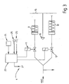
- FIG. 3 shows a block diagram of a non-inventive actuation system, including an electronic controller 23.
- the controller 23 is powered by means of a power supply 24, which may include, for example, a battery or a photovoltaic system, with electrical energy.
- the controller 23 includes an infrared sensor 25 and a manual override 26.
- This is both a non-contact basic function of Spülvor- - direction 1, for example by means of main sensor 5 and Nahsensoren 6a, 6b, as well as an additional manual operation ensures, for example, for disabled users the toilet at a suitable location, optionally on the backrest, the armrest or the like and for emergency or cleaning operations by maintenance or cleaning personnel.
- controller 23 allows driving an additional system 27, wherein, for example, a cleaning, disinfecting and / or fragrance agent can be added to the flushing medium if necessary.
- a fan can be controlled, which supplies the toilet room with fresh air.
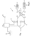
- FIG. 4 shows a block diagram with a so-called aerial intersection 28, as provided according to the invention.
- two air paths intersect, which represent the extension of two supply lines 29 and 30, wherein on the opposite side of the two supply lines 29 and 30 each have a corresponding outflow line 31 and 32 is arranged.
- valve 11 If, for example, the valve 11 is opened, water flows via the inflow line 29 into the air-line intersection 28 and further via the outflow line 32 into the cylinder-piston unit 10 and actuates it, so that a large amount of purging is released. The same applies to the opening of the valve 12, wherein ultimately a purge is triggered with a small flush volume.
- a level switch 34 connected to the controller 23 causes, by means of the controller 23, closing of the valves 11 and 12, so that the filling of the storage container 3 is stopped and overflow is prevented.
Landscapes
- Engineering & Computer Science (AREA)
- Health & Medical Sciences (AREA)
- Life Sciences & Earth Sciences (AREA)
- Hydrology & Water Resources (AREA)
- Public Health (AREA)
- Water Supply & Treatment (AREA)
- Aviation & Aerospace Engineering (AREA)
- Mechanical Engineering (AREA)
- Sanitary Device For Flush Toilet (AREA)
- Detergent Compositions (AREA)
Claims (13)
- Système de chasse d'eau (1) pour des toilettes (2) avec un récipient de stockage (3) et un système d'actionnement (4) pour le vidage du récipient de stockage (3),
où le système d'actionnement (4)- est de nature hydraulique ;- comprend au moins une soupape (11, 12) bistable ;- présente au moins une unité à piston et cylindre (9, 10),caractérisé en ce que- deux soupapes bistables (11, 12) et deux unités à piston et cylindre (9, 10) sont prévues ;- entre les deux soupapes (11, 12) et les deux unités à piston et cylindre (9, 10) est respectivement prévue une veine d'air (28) ; et- une conduite d' arrivée (29, 30) est disposée en amont, et une conduite d'évacuation (31, 32) est disposée en aval de chaque veine d'air (28) ;où- les veines d'air (28) d'au moins deux conduites d'amenée se croisent ; et- en cas d'ouverture simultanée des soupapes (11, 12), une ouverture d'évacuation (33) peut être commandée pour le remplissage du récipient de stockage (3). - Système de chasse d'eau (1) selon la revendication 1, caractérisé en ce que le système d'actionnement (4) comprend une commande (23) de nature électrique.
- Système de chasse d'eau (1) selon la revendication 1 ou 2, caractérisé en ce que le système d'actionnement (4) comprend une alimentation en énergie (24) électrique, indépendante du secteur.
- Système de chasse d'eau (1) selon l'une des revendications précédentes, caractérisé en ce que le système d'actionnement (4) comprend au moins un capteur (5, 6a, 6b, 25, 26) sans contact.
- Système de chasse d'eau (1) selon l'une des revendications précédentes, caractérisé en ce qu'au moins une commande automatique (23) est prévue.
- Système de chasse d'eau (1) selon l'une des revendications précédentes, caractérisé en ce qu'une commande de volume de chasse (23) est prévue.
- Système de chasse d'eau (1) selon l'une des revendications précédentes, caractérisé en ce que l'unité à piston et cylindre (9, 10) comprend une ouverture d'aération (19, 20) et une ouverture de vidange (21, 22).
- Système de chasse d'eau (1) selon l'une des revendications précédentes, caractérisé en ce que le système d'actionnement (4) comprend deux unités à piston et cylindre (9, 10) ayant des courses (x, y) différentes.
- Système de chasse d'eau (1) selon l'une des revendications précédentes, caractérisé en ce qu'un élément d'accouplement (15) est prévu, pour l'actionnement de systèmes de chasse d'eau (16) classiques.
- Système de chasse d'eau (1) selon l'une des revendications précédentes, caractérisé en ce qu'au moins un élément de manoeuvre (26) manuel est prévu.
- Système de chasse d'eau(1) selon l'une des revendications précédentes, caractérisé en ce qu'au moins un système additionnel (27) peut être commandé.
- Système de chasse d'eau (1) selon l'une des revendications précédentes, caractérisé en ce qu'une commande (23), dépendant du temps, d'au moins l'une des soupapes (11, 12) est prévue.
- Système de chasse d'eau (1) selon l'une des revendications précédentes, caractérisé en ce qu'au moins un capteur de niveau de remplissage (34) et/ou au moins un débitmètre est/sont prévu(s).
Applications Claiming Priority (2)
| Application Number | Priority Date | Filing Date | Title |
|---|---|---|---|
| DE10009253A DE10009253A1 (de) | 2000-02-28 | 2000-02-28 | Spülvorrichtung für Toiletten |
| DE10009253 | 2000-02-28 |
Publications (2)
| Publication Number | Publication Date |
|---|---|
| EP1127987A1 EP1127987A1 (fr) | 2001-08-29 |
| EP1127987B1 true EP1127987B1 (fr) | 2006-11-22 |
Family
ID=7632638
Family Applications (1)
| Application Number | Title | Priority Date | Filing Date |
|---|---|---|---|
| EP01104831A Expired - Lifetime EP1127987B1 (fr) | 2000-02-28 | 2001-02-27 | Système de chasse d'eau pour toilettes |
Country Status (3)
| Country | Link |
|---|---|
| EP (1) | EP1127987B1 (fr) |
| AT (1) | ATE346194T1 (fr) |
| DE (2) | DE10009253A1 (fr) |
Families Citing this family (16)
| Publication number | Priority date | Publication date | Assignee | Title |
|---|---|---|---|---|
| US6710006B2 (en) | 2000-02-09 | 2004-03-23 | Shell Oil Company | Non-symmetrical ligands and catalyst systems thereof for ethylene oligomerization to linear alpha olefins |
| US7037988B2 (en) | 2000-10-03 | 2006-05-02 | Shell Oil Company | Process for the co-oligomerisation of ethylene and alpha olefins |
| WO2002084035A1 (fr) * | 2001-04-12 | 2002-10-24 | Hendrik Andries Hanekom | Systeme de chasse d'eau pour toilettes ou urinoirs |
| ATE303475T1 (de) * | 2002-08-14 | 2005-09-15 | Geberit Technik Ag | Betätigungsvorrichtung für ein auslaufventil einer spülvorrichtung |
| WO2004037415A2 (fr) | 2002-09-25 | 2004-05-06 | Shell Internationale Research Maatschappij B.V. | Systemes de catalyseurs destines a l'oligomerisation d'ethylenes en olefines alpha lineaires |
| CN1934121A (zh) | 2004-03-24 | 2007-03-21 | 国际壳牌研究有限公司 | 过渡金属配合物 |
| EP1607531A1 (fr) * | 2004-06-18 | 2005-12-21 | Chih Chen Yen | Dispositif déchargeur automatique de chasse d'eau |
| AR049714A1 (es) | 2004-07-13 | 2006-08-30 | Shell Int Research | Proceso de preparacion de alfa olefinas lineales |
| FI20060931A0 (fi) * | 2006-10-23 | 2006-10-23 | Oras Oy | Laitteisto ja menetelmä WC-istuimen käyttäjän tunnistamiseksi ja huuhtelun suorittamiseksi |
| GB2443188A (en) * | 2006-10-25 | 2008-04-30 | House Of Janina Ltd | Cistern with hydraulically actuated valve |
| DE102011085352A1 (de) * | 2011-10-27 | 2013-05-02 | Rebecca Scherer | Einsetzbare Vorrichtung für Toiletten und Betten oder alternative Orte zum Aufheben oder Dämpfen von Toilettengang- und Schnarchgeräuschen |
| ITMI20130570A1 (it) * | 2013-04-10 | 2014-10-11 | Elia Bozzoli | Dispositivo di scarico selettivo dell'acqua di lavaggio per un vaso sanitario. |
| TR201619158A1 (tr) * | 2016-12-21 | 2018-07-23 | Eczacibasi Yapi Gerecleri Sanayi Ve Ticaret Anonim Sirketi | Bi̇r elektroni̇k kontrollü rezervuar si̇stemi̇ |
| IL271925B2 (en) * | 2020-01-09 | 2024-05-01 | Global One Tech Corp | Smart automatic flush toilet construction |
| ES2969227T3 (es) * | 2020-01-10 | 2024-05-17 | Global One Tech Corp | Construcción de inodoro inteligente con descarga automática |
| WO2022188047A1 (fr) * | 2021-03-10 | 2022-09-15 | 厦门倍洁特科技有限公司 | Appareil auto-alimenté par vanne d'entrée d'eau |
Family Cites Families (11)
| Publication number | Priority date | Publication date | Assignee | Title |
|---|---|---|---|---|
| US2858546A (en) * | 1956-12-10 | 1958-11-04 | Leonard Leclair | Electronic toilet flusher |
| CH366501A (de) * | 1959-01-12 | 1962-12-31 | Gebert & Cie | Hydraulische Betätigungsvorrichtung an Spülkasten-Ablaufventil |
| BE757657A (fr) * | 1969-10-18 | 1971-04-16 | Philips Nv | Dispositif devant assurer le rincage d'un water-closet et comportant unreservoir de chasse d'eau |
| US4138749A (en) * | 1977-08-04 | 1979-02-13 | Clark Merlin W | Two-stage hydraulic flush control device |
| US4631760A (en) * | 1984-07-25 | 1986-12-30 | Leishman Graham W | Automatic flushing system |
| US4809367A (en) * | 1986-08-08 | 1989-03-07 | Partall Systems (Proprietary) Limited | Cistern flushing apparatus |
| US5027444A (en) * | 1990-02-14 | 1991-07-02 | American Standard Inc. | Device providing automatic delivery of toilet bowl freshener |
| FR2681891A1 (fr) * | 1991-09-27 | 1993-04-02 | Ragot Claude | Perfectionnements aux dispositifs d'evacuation et de vidange rapide de liquide d'un reservoir de cuvette de w.c.. |
| FI99156C (fi) * | 1993-04-19 | 1997-10-10 | Evac Ab | Sähköohjauslaite |
| GB2317191B (en) * | 1996-09-04 | 2000-11-15 | Cistermiser Ltd | Valve apparatus for use in fluids storage vessels |
| TW335829U (en) * | 1997-05-02 | 1998-07-01 | jing-wei Zhong | Hydraulic toilet auto flush |
-
2000
- 2000-02-28 DE DE10009253A patent/DE10009253A1/de not_active Withdrawn
-
2001
- 2001-02-27 AT AT01104831T patent/ATE346194T1/de not_active IP Right Cessation
- 2001-02-27 EP EP01104831A patent/EP1127987B1/fr not_active Expired - Lifetime
- 2001-02-27 DE DE50111477T patent/DE50111477D1/de not_active Expired - Fee Related
Also Published As
| Publication number | Publication date |
|---|---|
| EP1127987A1 (fr) | 2001-08-29 |
| ATE346194T1 (de) | 2006-12-15 |
| DE10009253A1 (de) | 2001-08-30 |
| DE50111477D1 (de) | 2007-01-04 |
Similar Documents
| Publication | Publication Date | Title |
|---|---|---|
| EP1127987B1 (fr) | Système de chasse d'eau pour toilettes | |
| EP3241749B1 (fr) | Système et procédé d'élimination de fluide à partir d'un évier | |
| EP3129560B1 (fr) | Toilette sous vide pneumatique et compacte | |
| WO2016008812A1 (fr) | Unité pilote électropneumatique | |
| DE69719196T2 (de) | Schwimmerventil | |
| DE102011018809A1 (de) | Vakuumtoiletteneinheit mit Urinalfunktion | |
| EP2678482B1 (fr) | Installation d'évacuation, soupape et procédé de drainage des eaux grises pour un avion de ligne | |
| EP3314063A1 (fr) | Commande pneumatique pour des toilettes à aspiration | |
| DE8018966U1 (de) | Vakuum-spueltoilettensystem | |
| EP3004473A2 (fr) | Cartouche de commande pour robinetterie sanitaire | |
| DE19713504C1 (de) | Vakuumtoilettensystem und Verfahren zum Betreiben und zum Beseitigen von Verstopfungen | |
| DE102015214636A1 (de) | Inbetriebnahme und Außerbetriebnahme eines Toilettensystems | |
| DE4311066A1 (de) | Absaugvorrichtung für Toilettenbecken | |
| DE102005045343B4 (de) | Transfereinheit | |
| DE102010016524B4 (de) | Verfahren zum Überwachen und Steuern von Komponenten eines Unterdruckabwassersystems | |
| EP2447429A1 (fr) | Fermeture de retenue | |
| WO1998055706A9 (fr) | Systeme de toilettes a aspiration par le vide | |
| WO1992012299A1 (fr) | Water-closet, en particulier pour vehicules | |
| WO2019154708A1 (fr) | Unité de commande, unité de raccordement et dispositif de commande d'un système de toilettes à vide, système de toilettes à vide et procédé permettant de faire fonctionner un système de toilettes à vide | |
| DE10253890A1 (de) | Spülkastensteuerung | |
| DE2648171A1 (de) | Klosett mit luftaustauschvorrichtung | |
| DE202010014685U1 (de) | Doppel - Toilettenanordnung | |
| DE69003488T2 (de) | W.C. mit sehr geringem Spülwasserverbrauch und Verwendung von Druckluft als Energiequelle. | |
| DE10114428A1 (de) | Sanitäreinrichtung mit einem Spülkasten | |
| EP1217311A2 (fr) | Installation pour préparer de l'eau chaude dans une installation sanitaire |
Legal Events
| Date | Code | Title | Description |
|---|---|---|---|
| PUAI | Public reference made under article 153(3) epc to a published international application that has entered the european phase |
Free format text: ORIGINAL CODE: 0009012 |
|
| AK | Designated contracting states |
Kind code of ref document: A1 Designated state(s): AT BE CH CY DE DK ES FI FR GB GR IE IT LI LU MC NL PT SE TR |
|
| AX | Request for extension of the european patent |
Free format text: AL;LT;LV;MK;RO;SI |
|
| 17P | Request for examination filed |
Effective date: 20011221 |
|
| AKX | Designation fees paid |
Free format text: AT BE CH CY DE DK ES FI FR GB GR IE IT LI LU MC NL PT SE TR |
|
| GRAP | Despatch of communication of intention to grant a patent |
Free format text: ORIGINAL CODE: EPIDOSNIGR1 |
|
| GRAC | Information related to communication of intention to grant a patent modified |
Free format text: ORIGINAL CODE: EPIDOSCIGR1 |
|
| GRAS | Grant fee paid |
Free format text: ORIGINAL CODE: EPIDOSNIGR3 |
|
| GRAA | (expected) grant |
Free format text: ORIGINAL CODE: 0009210 |
|
| AK | Designated contracting states |
Kind code of ref document: B1 Designated state(s): AT BE CH CY DE DK ES FI FR GB GR IE IT LI LU MC NL PT SE TR |
|
| PG25 | Lapsed in a contracting state [announced via postgrant information from national office to epo] |
Ref country code: NL Free format text: LAPSE BECAUSE OF FAILURE TO SUBMIT A TRANSLATION OF THE DESCRIPTION OR TO PAY THE FEE WITHIN THE PRESCRIBED TIME-LIMIT Effective date: 20061122 Ref country code: IE Free format text: LAPSE BECAUSE OF FAILURE TO SUBMIT A TRANSLATION OF THE DESCRIPTION OR TO PAY THE FEE WITHIN THE PRESCRIBED TIME-LIMIT Effective date: 20061122 Ref country code: FI Free format text: LAPSE BECAUSE OF FAILURE TO SUBMIT A TRANSLATION OF THE DESCRIPTION OR TO PAY THE FEE WITHIN THE PRESCRIBED TIME-LIMIT Effective date: 20061122 |
|
| REG | Reference to a national code |
Ref country code: GB Ref legal event code: FG4D Free format text: NOT ENGLISH |
|
| REG | Reference to a national code |
Ref country code: CH Ref legal event code: EP |
|
| REG | Reference to a national code |
Ref country code: IE Ref legal event code: FG4D Free format text: LANGUAGE OF EP DOCUMENT: GERMAN |
|
| REF | Corresponds to: |
Ref document number: 50111477 Country of ref document: DE Date of ref document: 20070104 Kind code of ref document: P |
|
| PGFP | Annual fee paid to national office [announced via postgrant information from national office to epo] |
Ref country code: DE Payment date: 20070217 Year of fee payment: 7 |
|
| PGFP | Annual fee paid to national office [announced via postgrant information from national office to epo] |
Ref country code: GB Payment date: 20070219 Year of fee payment: 7 Ref country code: CH Payment date: 20070219 Year of fee payment: 7 |
|
| PGFP | Annual fee paid to national office [announced via postgrant information from national office to epo] |
Ref country code: AT Payment date: 20070221 Year of fee payment: 7 |
|
| PG25 | Lapsed in a contracting state [announced via postgrant information from national office to epo] |
Ref country code: SE Free format text: LAPSE BECAUSE OF FAILURE TO SUBMIT A TRANSLATION OF THE DESCRIPTION OR TO PAY THE FEE WITHIN THE PRESCRIBED TIME-LIMIT Effective date: 20070222 Ref country code: DK Free format text: LAPSE BECAUSE OF FAILURE TO SUBMIT A TRANSLATION OF THE DESCRIPTION OR TO PAY THE FEE WITHIN THE PRESCRIBED TIME-LIMIT Effective date: 20070222 |
|
| PG25 | Lapsed in a contracting state [announced via postgrant information from national office to epo] |
Ref country code: MC Free format text: LAPSE BECAUSE OF NON-PAYMENT OF DUE FEES Effective date: 20070228 |
|
| PG25 | Lapsed in a contracting state [announced via postgrant information from national office to epo] |
Ref country code: ES Free format text: LAPSE BECAUSE OF FAILURE TO SUBMIT A TRANSLATION OF THE DESCRIPTION OR TO PAY THE FEE WITHIN THE PRESCRIBED TIME-LIMIT Effective date: 20070305 |
|
| GBT | Gb: translation of ep patent filed (gb section 77(6)(a)/1977) |
Effective date: 20070308 |
|
| PG25 | Lapsed in a contracting state [announced via postgrant information from national office to epo] |
Ref country code: PT Free format text: LAPSE BECAUSE OF FAILURE TO SUBMIT A TRANSLATION OF THE DESCRIPTION OR TO PAY THE FEE WITHIN THE PRESCRIBED TIME-LIMIT Effective date: 20070423 |
|
| NLV1 | Nl: lapsed or annulled due to failure to fulfill the requirements of art. 29p and 29m of the patents act | ||
| REG | Reference to a national code |
Ref country code: CH Ref legal event code: NV Representative=s name: FREI PATENTANWALTSBUERO AG |
|
| REG | Reference to a national code |
Ref country code: IE Ref legal event code: FD4D |
|
| EN | Fr: translation not filed | ||
| PLBE | No opposition filed within time limit |
Free format text: ORIGINAL CODE: 0009261 |
|
| STAA | Information on the status of an ep patent application or granted ep patent |
Free format text: STATUS: NO OPPOSITION FILED WITHIN TIME LIMIT |
|
| ET | Fr: translation filed | ||
| REG | Reference to a national code |
Ref country code: FR Ref legal event code: EERR Free format text: CORRECTION DE BOPI 07/28 - BREVETS EUROPEENS DONT LA TRADUCTION N A PAS ETE REMISE A L INPI. IL Y A LIEU DE SUPPRIMER : LA MENTION DE LA NON REMISE. LA REMISE DE LA TRADUCTION EST PUBLIEE DANS LE PRESENT BOPI. |
|
| 26N | No opposition filed |
Effective date: 20070823 |
|
| BERE | Be: lapsed |
Owner name: AQUIS SANITAR A.G. Effective date: 20070228 |
|
| PG25 | Lapsed in a contracting state [announced via postgrant information from national office to epo] |
Ref country code: BE Free format text: LAPSE BECAUSE OF NON-PAYMENT OF DUE FEES Effective date: 20070228 |
|
| PGFP | Annual fee paid to national office [announced via postgrant information from national office to epo] |
Ref country code: IT Payment date: 20070627 Year of fee payment: 7 |
|
| PG25 | Lapsed in a contracting state [announced via postgrant information from national office to epo] |
Ref country code: GR Free format text: LAPSE BECAUSE OF FAILURE TO SUBMIT A TRANSLATION OF THE DESCRIPTION OR TO PAY THE FEE WITHIN THE PRESCRIBED TIME-LIMIT Effective date: 20070223 |
|
| PGFP | Annual fee paid to national office [announced via postgrant information from national office to epo] |
Ref country code: FR Payment date: 20070219 Year of fee payment: 7 |
|
| REG | Reference to a national code |
Ref country code: CH Ref legal event code: PL |
|
| GBPC | Gb: european patent ceased through non-payment of renewal fee |
Effective date: 20080227 |
|
| PG25 | Lapsed in a contracting state [announced via postgrant information from national office to epo] |
Ref country code: LI Free format text: LAPSE BECAUSE OF NON-PAYMENT OF DUE FEES Effective date: 20080229 Ref country code: CH Free format text: LAPSE BECAUSE OF NON-PAYMENT OF DUE FEES Effective date: 20080229 |
|
| PG25 | Lapsed in a contracting state [announced via postgrant information from national office to epo] |
Ref country code: AT Free format text: LAPSE BECAUSE OF NON-PAYMENT OF DUE FEES Effective date: 20080227 |
|
| PG25 | Lapsed in a contracting state [announced via postgrant information from national office to epo] |
Ref country code: DE Free format text: LAPSE BECAUSE OF NON-PAYMENT OF DUE FEES Effective date: 20080902 |
|
| PG25 | Lapsed in a contracting state [announced via postgrant information from national office to epo] |
Ref country code: GB Free format text: LAPSE BECAUSE OF NON-PAYMENT OF DUE FEES Effective date: 20080227 |
|
| PG25 | Lapsed in a contracting state [announced via postgrant information from national office to epo] |
Ref country code: LU Free format text: LAPSE BECAUSE OF NON-PAYMENT OF DUE FEES Effective date: 20070227 Ref country code: IT Free format text: LAPSE BECAUSE OF NON-PAYMENT OF DUE FEES Effective date: 20080227 Ref country code: CY Free format text: LAPSE BECAUSE OF FAILURE TO SUBMIT A TRANSLATION OF THE DESCRIPTION OR TO PAY THE FEE WITHIN THE PRESCRIBED TIME-LIMIT Effective date: 20061122 |
|
| PG25 | Lapsed in a contracting state [announced via postgrant information from national office to epo] |
Ref country code: TR Free format text: LAPSE BECAUSE OF FAILURE TO SUBMIT A TRANSLATION OF THE DESCRIPTION OR TO PAY THE FEE WITHIN THE PRESCRIBED TIME-LIMIT Effective date: 20061122 |
|
| PG25 | Lapsed in a contracting state [announced via postgrant information from national office to epo] |
Ref country code: FR Free format text: LAPSE BECAUSE OF NON-PAYMENT OF DUE FEES Effective date: 20080227 |
|
| REG | Reference to a national code |
Ref country code: FR Ref legal event code: ST Effective date: 20111021 |