EP1127993A1 - Glasbausteinwand - Google Patents
Glasbausteinwand Download PDFInfo
- Publication number
- EP1127993A1 EP1127993A1 EP01111536A EP01111536A EP1127993A1 EP 1127993 A1 EP1127993 A1 EP 1127993A1 EP 01111536 A EP01111536 A EP 01111536A EP 01111536 A EP01111536 A EP 01111536A EP 1127993 A1 EP1127993 A1 EP 1127993A1
- Authority
- EP
- European Patent Office
- Prior art keywords
- separation
- glass brick
- strip
- separation strip
- brick wall
- Prior art date
- Legal status (The legal status is an assumption and is not a legal conclusion. Google has not performed a legal analysis and makes no representation as to the accuracy of the status listed.)
- Granted
Links
- 239000011449 brick Substances 0.000 title claims abstract description 156
- 239000011521 glass Substances 0.000 title claims abstract description 146
- 238000000926 separation method Methods 0.000 claims abstract description 130
- 239000011324 bead Substances 0.000 claims description 9
- 239000000463 material Substances 0.000 claims description 6
- 238000005452 bending Methods 0.000 claims description 2
- 239000003550 marker Substances 0.000 claims description 2
- 101100313377 Caenorhabditis elegans stip-1 gene Proteins 0.000 claims 1
- 101100313382 Dictyostelium discoideum stip-2 gene Proteins 0.000 claims 1
- 101100516335 Rattus norvegicus Necab1 gene Proteins 0.000 claims 1
- 101150059016 TFIP11 gene Proteins 0.000 claims 1
- 238000010276 construction Methods 0.000 description 32
- 239000004411 aluminium Substances 0.000 description 15
- 229910052782 aluminium Inorganic materials 0.000 description 15
- XAGFODPZIPBFFR-UHFFFAOYSA-N aluminium Chemical compound [Al] XAGFODPZIPBFFR-UHFFFAOYSA-N 0.000 description 15
- 238000000034 method Methods 0.000 description 15
- 239000000853 adhesive Substances 0.000 description 10
- 230000001070 adhesive effect Effects 0.000 description 10
- 229920001296 polysiloxane Polymers 0.000 description 6
- 238000001125 extrusion Methods 0.000 description 5
- 239000004033 plastic Substances 0.000 description 4
- 229920003023 plastic Polymers 0.000 description 4
- 239000000945 filler Substances 0.000 description 3
- 238000005192 partition Methods 0.000 description 3
- 238000003780 insertion Methods 0.000 description 2
- 230000037431 insertion Effects 0.000 description 2
- 229910052751 metal Inorganic materials 0.000 description 2
- 239000002184 metal Substances 0.000 description 2
- 230000002093 peripheral effect Effects 0.000 description 2
- 230000000717 retained effect Effects 0.000 description 2
- 230000001627 detrimental effect Effects 0.000 description 1
- 238000010586 diagram Methods 0.000 description 1
- 230000000694 effects Effects 0.000 description 1
- 230000002452 interceptive effect Effects 0.000 description 1
- 238000004519 manufacturing process Methods 0.000 description 1
- 239000007769 metal material Substances 0.000 description 1
- 238000012986 modification Methods 0.000 description 1
- 230000004048 modification Effects 0.000 description 1
- 229920002635 polyurethane Polymers 0.000 description 1
- 239000004814 polyurethane Substances 0.000 description 1
- 230000007704 transition Effects 0.000 description 1
Images


Classifications
-
- E—FIXED CONSTRUCTIONS
- E04—BUILDING
- E04C—STRUCTURAL ELEMENTS; BUILDING MATERIALS
- E04C1/00—Building elements of block or other shape for the construction of parts of buildings
- E04C1/42—Building elements of block or other shape for the construction of parts of buildings of glass or other transparent material
-
- E—FIXED CONSTRUCTIONS
- E04—BUILDING
- E04G—SCAFFOLDING; FORMS; SHUTTERING; BUILDING IMPLEMENTS OR AIDS, OR THEIR USE; HANDLING BUILDING MATERIALS ON THE SITE; REPAIRING, BREAKING-UP OR OTHER WORK ON EXISTING BUILDINGS
- E04G21/00—Preparing, conveying, or working-up building materials or building elements in situ; Other devices or measures for constructional work
- E04G21/14—Conveying or assembling building elements
- E04G21/16—Tools or apparatus
- E04G21/18—Adjusting tools; Templates
- E04G21/1841—Means for positioning building parts or elements
-
- E—FIXED CONSTRUCTIONS
- E04—BUILDING
- E04G—SCAFFOLDING; FORMS; SHUTTERING; BUILDING IMPLEMENTS OR AIDS, OR THEIR USE; HANDLING BUILDING MATERIALS ON THE SITE; REPAIRING, BREAKING-UP OR OTHER WORK ON EXISTING BUILDINGS
- E04G21/00—Preparing, conveying, or working-up building materials or building elements in situ; Other devices or measures for constructional work
- E04G21/14—Conveying or assembling building elements
- E04G21/16—Tools or apparatus
- E04G21/18—Adjusting tools; Templates
- E04G21/1841—Means for positioning building parts or elements
- E04G21/1875—Means for positioning building parts or elements for making curved walls
-
- E—FIXED CONSTRUCTIONS
- E04—BUILDING
- E04G—SCAFFOLDING; FORMS; SHUTTERING; BUILDING IMPLEMENTS OR AIDS, OR THEIR USE; HANDLING BUILDING MATERIALS ON THE SITE; REPAIRING, BREAKING-UP OR OTHER WORK ON EXISTING BUILDINGS
- E04G21/00—Preparing, conveying, or working-up building materials or building elements in situ; Other devices or measures for constructional work
- E04G21/14—Conveying or assembling building elements
- E04G21/16—Tools or apparatus
- E04G21/18—Adjusting tools; Templates
- E04G21/1841—Means for positioning building parts or elements
- E04G21/1883—Spacers, e.g. to have a constant spacing between courses of masonry
Definitions
- THIS INVENTION relates to a glass brick wall or partition and in particular, but not limited to an improved method of construction of a glass brick wall or partition using an improved support frame.
- glass bricks are usually box like in shape being made from two hollow halves welded together. This results in a central weld bead between marginal ridges forming a peripheral channel around the glass brick. Channels of adjacent bricks are placed side-by-side and grouting or other filler is used to fill the channel between adjacent glass bricks and a wall is made up in this fashion.
- a curved glass brick wall including a separation strip between adjacent horizontal runs of glass bricks, the strip having cut-out portions at spaced intervals between straight strip sections so that the cut-out portions provide a bending site so adjacent strip sections in the wall are angled relative to one another to provide an overall curve.
- each glass brick is made from edge welded together dish-like sections having a weld bead extending around the brick in a shallow recessed side wall thereof, each separation strip being self locating in adjacent recesses of adjacent horizontal runs of bricks, each separation strip having transversely spaced pairs of back-to-back channels for holding jointing paste and opposed relatively thick longitudinally extending marginal edge portions adjacent the channels and there being provided at the juncture between the channels and the marginal edge portions, recess register means adapted to project into the glass brick recess to automatically locate the separation strip, each pair of back-to-back channels sharing a relatively thin wall and the separation strip having a relatively thick central medial portion located over the weld bead.
- a glass brick wall comprising a plurality of generally rectangular glass bricks layed in horizontal runs between spaced elongated vertically extending support frame members, the wall having horizontally extending elongated separation strips between adjacent horizontal runs, characterised in that, the separation strips have opposed longitudinally extending beading locating the separation strips between the runs of bricks and each separator strip being supported at its end by a bracket having a support member projecting into a space between the channel of an adjacent glass brick and the separation strip.
- a glass brick wall having a support assembly utilising channels so formed in the glass bricks to support a separation strip between adjacent glass bricks, the separation strip having opposed longitudinally extending beading locating the separation strip in said channels of said adjacent glass bricks and the separation strip being supported at its end by a bracket having a support member projecting into a space between the channel of an adjacent glass brick and the separation strip.
- the bracket support members are typically a plurality of fingers adapted to straddle the separation strip thereby projecting into the channels of adjacent glass bricks with fingers projecting into the channels above and below the separation strip.
- the fingers are typically about the same thickness as the beading so that the fingers locate flush or below the beading in the separation strips.
- two fingers are positioned on either side of the separation strip, the fingers protruding generally at 90° to the bracket body, the bracket body being generally planar and being adapted to be fastened to a wall, frame or the like.
- the bracket includes a marker or position indicating means so the bracket can be located at a predetermined position so that the separation strip supported by the bracket is positioned generally at 90° to the wall or support to which the bracket is fitted.
- the support frame members can be of any desirable shape but are typically box-like or channel-like in section.
- the support frame members have a channel-like cross-section including a bridging web section extending between opposed flanges.
- Each flange can include one or more return flanges,
- the web section includes an outer face and a vertical run of bricks abut against the outer face, the outer face of the web section presenting a face incorporating vertically spaced apertures receiving the separation strips.
- the return flanges are of a sufficient size to enable the separation strips to be securely supported by the flanges, the return flanges and the apertures.
- the return flange is slotted to receive the separation strip.
- a frangible join is formed in the extrusion process.
- the frangible joins are in the form of a V-shaped notch so that a marginal portion of a flange can be snapped off from the support frame at the V-shaped notch, if the marginal portion of the flange is not required for the construction of the glass brick wall.
- the apertures can be of any desired shape but are preferably generally matched to the section of the separation strips to provide a tight fit.
- the apertures comprise spaced horizontal slots.
- the separation strips are also adhered firmly to the support frame on an opposite surface to the slots in the C-shaped channel.
- Each glass brick is typically made form edge welded together dish-like sections having a weld bead extending around the brick in a shallow recessed side wall thereof, each of the separation strips being self locating in adjacent recesses between glass bricks of adjacent horizontal runs.
- each separation strip has transversely spaced pairs of back-to-back channels for holding jointing paste and opposed relatively thick marginal edge portions being transversely spaced and separated by recess register means adapted to project Into the glass brick recess to automatically locate the separation strips, each pair of back-to-back channels sharing a relatively thin wall and the separation strip having a relatively thick central medial portion located over the weld bead.
- the separation strips can be produced from plastics or metal materials known in the building or construction industries. Further, these plastics or metal separation strips can be produced to give a constant space between each glass brick in the glass brick wall in both the horizontal and vertical planes so that the glass brick wall can be accurately built.
- the separation strips can be made from extruded aluminium having any suitable cross sectional profile for the construction of the glass brick wall of the present invention.
- a typical separation strip involves an elongate strip of thin sheet material marginally narrower than a side wall of a glass brick, the glass brick being of the type made from welded together halves where the side wall has a relatively wide and shallow recess extending around the glass brick and a weld bead generally centrally disposed in the recess, the strip having opposed marginal edge portions adapted to fit between adjacent glass bricks just beyond the shallow recess and having tapered recess register means merging from the marginal edge portions and extending into the shallow recesses of adjacent glass bricks, so that the separation strip is automatically centred in the recesses of adjacent glass bricks.
- the separation strip typically employs spaced pairs of back-to-back channels for holding jointing paste, the channels being inboard of the recess register means and being bounded by the recess register means and inner elongate beading members, the marginal edge portions being relatively thick and the back to back channels being separated by a relatively thin shared wall so as to minimise the amount of material used in the separation strip without compromising strength.
- the strip in order to maintain the strength of the strip, includes a medially bulged portion having back-to-back relatively narrow channels positioned and adapted to accommodate the respective weld beads of the adjacent glass bricks.
- the separation strip is segmented and manipulated to provide a non-planar glass brick wall.
- the segmented separation strip has transverse divisions extending outwardly from each side of the medial portion of the separation strip.
- the transverse divisions in the separation strips are in the form of wedge shaped cut-out segments so that the medial portion between the cut out segments can be manipulated to follow a predetermined shape, for example, to form a curved glass brick wall.
- the cut out segments are stamped or cut out of the separation strips so that successive cutout segments are at intervals coinciding with the lengths of the glass bricks being used in the construction of the glass brick wall.
- the lengths of glass bricks used in the construction of glass brick walls include 240mm, 115mm, 190mm, 146mm or 300mm.
- the cut out segments in the separation strips can be cut or stamped out of any suitable width so that as each glass brick is positioned on the segmented separation strips, enough space is allowed between each glass brick for the construction of the curved glass brick wall.
- the cut out segments have a width of about 10mm.
- the segmented separation strips used are secured to the support frame using any suitable securing means.
- the securing means is in the form of a horse shoe shaped brace so that the brace can be located in the cut out segments of the separation strips that are inserted into the slots in the support frame.
- the horse shoe shaped braces are secured onto the support frame so that the segmented separation strips remain in a fixed position in relation to the support frame.
- the extruded aluminium support frame may be manufactured with longitudinally extending V-shaped grooves running along the length of the face incorporating the apertures so that adhesive can be applied in the desired position to achieve optimum performance of the adhesive when constructing the glass brick wall.
- FIG. 1 there is illustrated a partly completed construction of a glass brick wall 1 of the present invention.
- the glass brick wall 1 is constructed using glass bricks 2 and a support frame 3.
- the support frame 3 is in the form of a C-shaped channel 8 with a supporting surface in the form of a full surface 5 having glass bricks 2 abutted directly against the full surface 5.
- the full surface 5 has two V-shaped grooves 6 to allow an adhesive to be easily and correctly positioned on the full surface 5 before the glass bricks 2 are placed in position.
- the adhesive is in the form of a silicone constructor seal 7.
- the support frame 3 in the form of C-shaped channel 8 is manufactured from aluminium and can be extruded using techniques known in the aluminium extrusion industry.
- the separation strips 4 are manufactured using PVC plastics.
- the PVC separation strips 4 have a number of grooves 10 formed in both surfaces of the strips 4. Typically five grooves 10 are formed on each surface of the separation strips 4 so that either silicone constructor seal 7 and/or grouting 11 can be easily applied into the correct positions via the grooves 10 when constructing the glass brick wall 1.
- the separation strips 4 are precut to the dimensions of a particular job for the glass brick wall 1.
- the separation strips 4 are placed between each glass brick 2 in the glass brick wall 1 in both horizontal and vertical directions.
- the separation strips 4 used in the horizontal direction are one piece and extend between vertically spaced support frames 3 of the glass brick wall 1. These one piece separation strips 4 are cut to a length so that they can be inserted into apertures which in this case are vertically spaced slots 9 in the full surface 5 of the support frame 3 to provide greater support to the glass brick wall 1.
- the separation strips 4 in the vertical direction are cut to fit in between the glass bricks 2 and the lengths of the horizontal separation strips 4 so that each glass brick 2 is framed and correctly positioned in the glass brick wall 1.
- the full surface 5 of the support frame 3 has apertures In the form of slots 9.
- the slots 9 are cut into the full surface 5 at predetermined positions to coincide with the dimensions of the glass bricks 2 and the separation strips 4.
- the slots 9 are made of a width wide enough to allow the insertion of the separation strips 4 through into the C-shaped channel 8 of the support frame 3.
- the glass brick wall 1 can be successfully constructed to fit any reasonable application in the building and construction industries.
- a plan view shows a cut-away section of a glass brick 2 abutting directly against a support frame 3 and a separation strip 4.
- the support frame 3 is in the form of a C-shaped channel 8 with a supporting surface in the form of a full surface 5.
- the support frame 3 is manufactured from aluminium and is formed using extrusion techniques known to a skilled person in the aluminium construction industries.
- the full surface 5 of the support frame 3 is formed with apertures in the from of slots 9 at predetermined positions in the full surface 5 to allow the glass bricks 2 to be correctly placed and easily positioned in the glass brick wall 1.
- the full surface 5 of the support frame 3 has two V-shaped grooves 6 formed in the full surface 5 so that the silicone constructor seal 7 can be easily applied and correctly positioned on the full surface 5 of the support frame 3.
- the support frame 3 has means in the form of return flanges 12 positioned on an inside surface of the C-shaped channel 8 of the support frame 3 so that further support can be provided to the inserted separation strip 4, These return flanges are typically slotted to take the separation strip.
- an unsightly gap in the open surface of the C-shaped channel 8 which normally is concealed by a surrounding structure or wall of the building is revealed.
- This gap can be covered using a clip-on section 13 which can be made from either aluminium or plastics material.
- FIG. 3 there is illustrated a sectional view of a preferred form of the separation strip 4.
- FIG 4 there is illustrated a method of securing the support frame 3 onto a surrounding structure 14 of a wall or building.
- a flashing 15 can be placed into position and secured by nails 17 or the like to help stop any moisture from seeping into the glass brick wall 1.
- the support frame 3 can be secured to the surrounding structure 14 by using any suitable securing means known to a skilled person in the art.
- the securing means is in the form of a screw 16 which is screwed through both the support frame 3 and flashing 15 into the surrounding structure 14.
- a screwdriver 18 is passed through the slot 9 to enable the screw 16 to be screwed into the surrounding structure 14.
- FIG 5 there is illustrated a sectional view of another preferred embodiment of a separation strip 20 for the construction of the glass brick wall shown in Figures 1 and 2.
- the separation strip 20 is extruded from aluminium so that increased rigidity and safety features can be incorporated into the construction of the glass brick wall of the present invention.
- the extruded aluminium separation strip 20 has a central groove 21 extruded into both top and bottom surfaces of the strip 20 so that adhesives can be accurately placed onto the strip 20.
- the separation strip 20 has marginal edge grooves 22, 23 along each side edge of the strip 20 so that adhesives and/or grouting can be placed in between the glass bricks in the wall (not shown).
- Arrow shaped recess register means 55 help to locate the separation strip between adjacent glass bricks.
- FIG. 6 there is illustrated a sectional view of another preferred embodiment of a separation strip in the form of an extruded aluminium separation strip 30.
- the extruded aluminium strip 30 is manufactured in the extrusion process with a central, side and connecting portions 31, 32 and 33 respectively.
- the side portions 32 are extruded with recessed marginal edge portions 35 on both side edges of the separation strip 30 to allow the efficient and accurate insertion of adhesives and/or grouting in the construction process of the glass brick wall.
- Additional channels are provided by a shared wall 33 between the central and side portions 31 and 32, the wall 33 being extruded having a narrower gauge of aluminium so that the quantity of aluminium used in the extrusion process is kept to a minimum.
- the shared wall of channels 34 is thicker to maintain strength.
- FIG 7 there is illustrated a pictorial view of a partially completed construction of a curved glass brick wall of the present invention using the same glass bricks 2 as shown in Figures 1 and 2.
- the separation strips 30 are in the form of segmented separation strips 40 so that the segmented separation strips 40 can be bent to follow a predetermined shape of the curve in the glass brick wall under construction.
- the segmented separation strips are formed by cutting or stamping out transverse outwardly extending or wedge shaped divisions from each side of the central portion 31 of the separation strips 30.
- the transverse extending divisions are in the form of cut-out segments 41.
- the central portions 31 remaining between the cut-out segments 41 in the segmented separation strips 40 are then bent to follow the predetermined shape of the curve in the glass brick wall 50.
- the cut-out segments 41 are cut or stamped out in the segmented separation strips 40 so that the successive cut-out segments 41 are at intervals coinciding with the length of the glass bricks 2 used in the construction of the curved glass brick wall 50.
- the spaces between the glass bricks 2 and the segmented separation strips 40 are filled with any suitable expanding setting filler and can take the form of a polyurethane filler 42 and/or grouting 11 which is well known to a person skilled in the glass brick or building industries.
- the support frame 3 has along each side edge of its full surface 5 side extensions. These side extensions are in the form of side support flanges 44 and are of sufficient size so that, if required, the segmented separation strips 40 are securely supported by both the side support flanges 44 and the support frame 3.
- FIG. 7 The circled expanded view of Figure 7 illustrates the side support flanges 44 being a part of the C-shaped support frame extruded from a single piece of aluminium where the side support flanges 44 and the support frame 3 intersect, a frangible join in the form of a V-shaped notch 45 is formed so that the side support flanges 44 can be snapped off from the support frame 3 at the V-shaped notch 45 if the flanges 44 are not required for the construction of the curved glass brick wall 50.
- Figure 7 further illustrates a clip-on section also extruded from a single piece of aluminium and is in the form of a clip-on section 46 having an outwardly extending support panel 47.
- the support panel 47 is used to fix the support frame to the surrounding building panels (not shown) so that the glass brick wall 50 is securely held in position.
- a frangible join in the form of a V-shaped notch 45 is formed as in the case for the frangible join between the side support flanges 44 and the support frame 3.
- the segmented separation strips 40 are secured to the support frame 3 by a securing means in the form of horse shoe shaped braces 43.
- the horse shoe shaped braces 43 are located in the cut-out segments 41 inserted into the slots 9 in the support frame 3 so that the segmented separation strips 40 can remain in a fixed position in relation to the support frame 3.
- FIG. 8 there is a plan view illustrating the segmented separation strip 40 inserted into and secured to the support frame 3 for the construction of the curved glass brick wall 50.
- the segmented separation strip 40 is secured to the support frame 3 using the horse shoe shaped brace 43 located in the cut-out segment 41 inserted into slot 9 of the support frame 3.
- the segmented separation strip 40 is bent at the central portions 31 between the successive cut-out segments 41 so that the strips 40 follow the predetermined shape of the curve in the glass brick wall 50.
- Figure 8 also illustrates the successive cut-out segments 41 coinciding with the lengths of each glass brick 2 so that the glass bricks 2 when positioned on the segmented separation strips 40 follow the predetermined shape of the curve bent into the segmented separation strips 40 to form the glass brick wall 50 of the present invention.
- a separation strip 100 having opposed marginal edge portions 101 and 102 of relatively thick material, the opposed marginal edge portions 101 and 102 merging into tapered sections 103 and 104 terminating in shoulders 105 and 106.
- the strip includes back-to-back channels 107 and 108 where the adjoining walls 109 and 110 are deliberately made thin to minimise the amount of material employed to make the strip.
- the strip In order to strengthen the strip, it includes a relatively thick section 110 centrally disposed, the relatively thick section 110 having back-to-back relatively narrow channels 111 and 112.
- Figure 10 illustrates how the strip of Figure 1 is used, and as can be seen, two glass bricks 113 and 114 are placed together with the separation strip 100 between them.
- the glass bricks include welds 115 and recesses 116 and 117.
- the channels 111 and 112 accommodate the welds 115 while a jointing paste in the form of silicone gel for example, is placed in the back-to-back channels 107 and 108.
- Grouting 118 is employed to complete the assembly.
- the tapered sections 103 and 104 of the strip serves as a recess register means in that the strip is automatically centred in the recesses 116 and 117.
- tapers 103 and 104 Another feature of the tapers 103 and 104 is that some glass bricks have a steeper shoulder or transition region from the edge 121 of the glass brick to the respective recesses 116 and 117.
- the strip 100 clearly can also be used with this kind of glass brick.
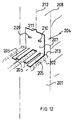
- a glass brick wall 200 comprising a plurality of glass bricks 201, the glass bricks 201 being supported by separation strips 202 carrying beading 203 and being held in place by brackets 204, the brackets 204 having projecting fingers 205 which are adapted to extend into channels 206 of the glass bricks 201 so the fingers 205 are disposed between the separation strips and the glass bricks.
- the bracket 204 includes a plate section 207 secured to a timber frame 208 by a pair of screws 209 and 210, the bracket 204 being located in place by aligning the pointer portion 210 with a locating line 212 drawn on the timber frame 208. This enables the bracket 204 to be located in the proper position so that the separation strip 202 (shown in phantom) is automatically positioned correctly due to the position of the projecting fingers 205. As can be seen, the fingers 205 have been positioned to straddle the end 213 on the separation strip 202.
- the fingers 205 are just thick enough so that they do not extend above the beading on the separation strip 202 so that they fit flush and are positioned between the separation strip and the adjacent glass bricks without interfering with the positioning of the glass bricks in the glass brick wall.
- the brackets 204 are typically made from sheet metal stamped into the general shape illustrated in Figure 12.
Landscapes
- Engineering & Computer Science (AREA)
- Architecture (AREA)
- Civil Engineering (AREA)
- Structural Engineering (AREA)
- Mechanical Engineering (AREA)
- Finishing Walls (AREA)
- Glass Compositions (AREA)
- Conveying And Assembling Of Building Elements In Situ (AREA)
- Joining Of Glass To Other Materials (AREA)
- Gas-Filled Discharge Tubes (AREA)
- Investigating Or Analyzing Materials By The Use Of Ultrasonic Waves (AREA)
- Securing Of Glass Panes Or The Like (AREA)
Applications Claiming Priority (11)
| Application Number | Priority Date | Filing Date | Title |
|---|---|---|---|
| AUPM055693 | 1993-08-13 | ||
| AUPM055693 | 1993-08-13 | ||
| AUPM210593 | 1993-10-28 | ||
| AUPM210593 | 1993-10-28 | ||
| AUPM248493 | 1993-11-17 | ||
| AUPM248493 | 1993-11-17 | ||
| AUPM2827A AUPM282793A0 (en) | 1993-12-06 | 1993-12-06 | Improved glass brick wall system |
| AUPM282793 | 1993-12-06 | ||
| AUPM6385A AUPM638594A0 (en) | 1994-06-21 | 1994-06-21 | Support assembly |
| AUPM638594 | 1994-06-21 | ||
| EP94924153A EP0713553B1 (de) | 1993-08-13 | 1994-08-15 | Wand aus glasbausteinen |
Related Parent Applications (1)
| Application Number | Title | Priority Date | Filing Date |
|---|---|---|---|
| EP94924153A Division EP0713553B1 (de) | 1993-08-13 | 1994-08-15 | Wand aus glasbausteinen |
Publications (2)
| Publication Number | Publication Date |
|---|---|
| EP1127993A1 true EP1127993A1 (de) | 2001-08-29 |
| EP1127993B1 EP1127993B1 (de) | 2003-11-12 |
Family
ID=27507438
Family Applications (2)
| Application Number | Title | Priority Date | Filing Date |
|---|---|---|---|
| EP94924153A Expired - Lifetime EP0713553B1 (de) | 1993-08-13 | 1994-08-15 | Wand aus glasbausteinen |
| EP01111536A Expired - Lifetime EP1127993B1 (de) | 1993-08-13 | 1994-08-15 | Glasbausteinwand |
Family Applications Before (1)
| Application Number | Title | Priority Date | Filing Date |
|---|---|---|---|
| EP94924153A Expired - Lifetime EP0713553B1 (de) | 1993-08-13 | 1994-08-15 | Wand aus glasbausteinen |
Country Status (10)
| Country | Link |
|---|---|
| US (1) | US5740646A (de) |
| EP (2) | EP0713553B1 (de) |
| AT (2) | ATE254224T1 (de) |
| AU (1) | AU698489B2 (de) |
| CA (1) | CA2169436A1 (de) |
| DE (2) | DE69433333T2 (de) |
| DK (1) | DK1127993T3 (de) |
| ES (2) | ES2211693T3 (de) |
| PT (2) | PT713553E (de) |
| WO (1) | WO1995005510A1 (de) |
Cited By (4)
| Publication number | Priority date | Publication date | Assignee | Title |
|---|---|---|---|---|
| WO2002012651A1 (en) * | 2000-06-21 | 2002-02-14 | Jon Cato Olsen | Method and device for building with glass blocks |
| WO2004097137A1 (en) | 2003-05-02 | 2004-11-11 | David Richardson | Glass brick and method of production thereof |
| FR2919316A1 (fr) * | 2007-07-23 | 2009-01-30 | Altiver Sarl | Systeme d'elevation d'une paroi de blocs de verre,au moins partiellement courbe |
| CN105863283A (zh) * | 2016-06-03 | 2016-08-17 | 中冶建工集团有限公司 | 用于控制灰缝厚度的垫层及采用该垫层的砌体安装结构 |
Families Citing this family (25)
| Publication number | Priority date | Publication date | Assignee | Title |
|---|---|---|---|---|
| AUPN072195A0 (en) * | 1995-01-24 | 1995-02-16 | Wirkus, Michelle Ann | Separation means for glass block wall |
| AU1208300A (en) * | 1998-10-26 | 2000-05-15 | Hy-Lite Products, Inc. | Block window system with border frame |
| DE19941685C1 (de) | 1999-09-01 | 2000-07-20 | Siemens Ag | Verfahren und Einrichtung zur Erhöhung des Drucks eines Gases |
| DE10105891B4 (de) * | 2001-02-09 | 2004-08-05 | Daimlerchrysler Ag | Verfahren zur Geräuschdämpfung von aufeinanderfolgenden Bauteilen sowie Geräuschabsorber für aufeinanderfolgende Bauteile |
| US20040088936A1 (en) * | 2002-11-07 | 2004-05-13 | Brian Wright | Spacer system for glass block walls |
| AU2003287112A1 (en) * | 2002-12-18 | 2004-07-09 | Arkadiusz Muszynski | Wall construction using hollow glass building elements |
| US7373763B2 (en) * | 2003-03-13 | 2008-05-20 | Extech/Exterior Technologies, Inc. | Glass block assembly |
| GB0306423D0 (en) * | 2003-03-20 | 2003-04-23 | Proffer Glass Engros As | System for building with glass blocks |
| US7243468B2 (en) * | 2003-04-10 | 2007-07-17 | Seattle Glass Block | System to lay out the position of glass blocks for construction of a glass block wall |
| USD494042S1 (en) | 2003-04-30 | 2004-08-10 | Seattle Glass Block | Glass block spacer |
| ITVE20030023A1 (it) * | 2003-06-10 | 2004-12-11 | Aghebo Sistemi S R L | Complesso di elementi strutturali per realizzare pareti in vetroresina. |
| DE10335633A1 (de) * | 2003-08-04 | 2005-03-03 | Brand, Daniel | Bauteil aus Glasbausteinen |
| ES2261001B1 (es) * | 2004-04-05 | 2007-10-01 | Decorchapa, S.L. | Estructura modular revestida, para el montaje de bloques. |
| US20050241268A1 (en) * | 2004-04-21 | 2005-11-03 | Horace Tjakra | Rigid spacer for glass block window assemblies |
| US20060272250A1 (en) * | 2005-05-09 | 2006-12-07 | John Friesen | Glass block panel anchor and reinforcing system |
| US7587870B2 (en) * | 2006-02-21 | 2009-09-15 | Extech/Exterior Technologies, Inc. | Grid system for mounting building blocks |
| US7426805B2 (en) * | 2006-02-21 | 2008-09-23 | Extech/Exterior Technologies, Inc. | Building block assembly system |
| FR2958670A1 (fr) * | 2010-04-09 | 2011-10-14 | Sadika Keskes | Element de construction par soufflage ou soufflage-pressage. |
| ES2674810B1 (es) * | 2016-12-30 | 2019-04-09 | Calvo Hernandez Ana Maria | Perfil autoadhesivo para el montaje de bloques constructivos fabricados en vidrio. |
| US11072971B1 (en) * | 2020-01-24 | 2021-07-27 | Solar Innovations, Inc. | Modular system for glazing and other infill panels |
| US11773599B2 (en) | 2021-02-12 | 2023-10-03 | Piazza Stone, Llc | Systems, devices, and methods for mounting a lightweight architectural masonry product to a building |
| CN113638619B (zh) * | 2021-08-18 | 2022-09-30 | 中铁五局集团路桥工程有限责任公司 | 一种旋转式玻璃幕墙破碎修补机构及其使用方法 |
| US12331525B2 (en) * | 2022-09-21 | 2025-06-17 | Hohmann & Barnard, Inc. | Dual-sided mounting bracket |
| CN115506610B (zh) * | 2022-10-22 | 2024-06-11 | 中建五局(烟台)建设工程有限公司 | 一种预制装配式建筑叠合板定位工具及其使用方法 |
| USD1109369S1 (en) * | 2025-04-15 | 2026-01-13 | Huimin Tian | Glass block frame |
Citations (3)
| Publication number | Priority date | Publication date | Assignee | Title |
|---|---|---|---|---|
| US2141000A (en) * | 1938-03-12 | 1938-12-20 | Revere Copper & Brass Inc | Wall or the like |
| US4965975A (en) * | 1989-02-23 | 1990-10-30 | Willi Schwarz | Means for erecting a wall of wall blocks, preferably of glass |
| US4986048A (en) * | 1990-01-11 | 1991-01-22 | Pittsburgh Corning Corporation | Method and apparatus for erecting a glass block wall |
Family Cites Families (12)
| Publication number | Priority date | Publication date | Assignee | Title |
|---|---|---|---|---|
| US2281524A (en) * | 1940-11-25 | 1942-04-28 | Meyers Company | Glass building block |
| ZA735104B (en) * | 1972-08-01 | 1974-07-31 | Mercer F Ltd | Building elements |
| IT1136411B (it) * | 1980-06-17 | 1986-08-27 | Oddo Borghetto | Complesso di elementi distanziatori e allineatori per blocchetti particolarmente adatti per pareti o pannelli in vetro cemento |
| DE3328791A1 (de) * | 1983-02-12 | 1985-02-28 | August Dr.-Ing. 5430 Montabaur Albers | Glasbausteinwand |
| FR2566444B1 (fr) * | 1984-06-22 | 1987-04-03 | Rochere | Procede de realisation de parois a partir d'elements parallelepipediques et dispositif pour la mise en oeuvre de ce procede |
| DE8437071U1 (de) * | 1984-12-18 | 1985-06-13 | Westerwald AG für Silikatindustrie, 5432 Wirges | Ecken-Glasstein |
| US4916876A (en) * | 1988-06-03 | 1990-04-17 | Schuyler Stephen V C | Glass block wall construction |
| US4918882A (en) * | 1988-12-21 | 1990-04-24 | Texas Aluminum Industries, Inc. | Glazing retainer assembly |
| US5010704A (en) * | 1990-05-21 | 1991-04-30 | Thompson Earl G | Glass block construction assembly |
| US5031372A (en) * | 1990-09-04 | 1991-07-16 | Mccluer Steve | Modular frame assembly for mounting glass blocks |
| US5430985A (en) * | 1990-09-14 | 1995-07-11 | Coleman; William J. | Building block wall connector strip and method of assembling a block wall utilizing such strip |
| US5067295A (en) * | 1990-09-18 | 1991-11-26 | Pittsburgh Corning Corporation | 45 degree block |
-
1994
- 1994-08-15 AT AT01111536T patent/ATE254224T1/de not_active IP Right Cessation
- 1994-08-15 DE DE69433333T patent/DE69433333T2/de not_active Expired - Lifetime
- 1994-08-15 CA CA002169436A patent/CA2169436A1/en not_active Abandoned
- 1994-08-15 DK DK01111536T patent/DK1127993T3/da active
- 1994-08-15 PT PT94924153T patent/PT713553E/pt unknown
- 1994-08-15 WO PCT/AU1994/000472 patent/WO1995005510A1/en not_active Ceased
- 1994-08-15 EP EP94924153A patent/EP0713553B1/de not_active Expired - Lifetime
- 1994-08-15 ES ES01111536T patent/ES2211693T3/es not_active Expired - Lifetime
- 1994-08-15 ES ES94924153T patent/ES2168307T3/es not_active Expired - Lifetime
- 1994-08-15 AT AT94924153T patent/ATE209280T1/de active
- 1994-08-15 DE DE69429178T patent/DE69429178T2/de not_active Expired - Fee Related
- 1994-08-15 PT PT01111536T patent/PT1127993E/pt unknown
- 1994-08-15 EP EP01111536A patent/EP1127993B1/de not_active Expired - Lifetime
- 1994-08-15 US US08/591,561 patent/US5740646A/en not_active Expired - Fee Related
- 1994-08-15 AU AU74530/94A patent/AU698489B2/en not_active Ceased
Patent Citations (3)
| Publication number | Priority date | Publication date | Assignee | Title |
|---|---|---|---|---|
| US2141000A (en) * | 1938-03-12 | 1938-12-20 | Revere Copper & Brass Inc | Wall or the like |
| US4965975A (en) * | 1989-02-23 | 1990-10-30 | Willi Schwarz | Means for erecting a wall of wall blocks, preferably of glass |
| US4986048A (en) * | 1990-01-11 | 1991-01-22 | Pittsburgh Corning Corporation | Method and apparatus for erecting a glass block wall |
Cited By (5)
| Publication number | Priority date | Publication date | Assignee | Title |
|---|---|---|---|---|
| WO2002012651A1 (en) * | 2000-06-21 | 2002-02-14 | Jon Cato Olsen | Method and device for building with glass blocks |
| WO2004097137A1 (en) | 2003-05-02 | 2004-11-11 | David Richardson | Glass brick and method of production thereof |
| FR2919316A1 (fr) * | 2007-07-23 | 2009-01-30 | Altiver Sarl | Systeme d'elevation d'une paroi de blocs de verre,au moins partiellement courbe |
| EP2022904A1 (de) * | 2007-07-23 | 2009-02-11 | Altiver Sarl | System zum Errichten einer zumindest teilweise gekrümmten Wand aus Glasbausteinen |
| CN105863283A (zh) * | 2016-06-03 | 2016-08-17 | 中冶建工集团有限公司 | 用于控制灰缝厚度的垫层及采用该垫层的砌体安装结构 |
Also Published As
| Publication number | Publication date |
|---|---|
| DE69429178T2 (de) | 2002-07-25 |
| DE69433333D1 (de) | 2003-12-18 |
| PT713553E (pt) | 2002-04-29 |
| PT1127993E (pt) | 2004-03-31 |
| DE69433333T2 (de) | 2004-09-09 |
| DK1127993T3 (da) | 2004-03-22 |
| WO1995005510A1 (en) | 1995-02-23 |
| EP1127993B1 (de) | 2003-11-12 |
| CA2169436A1 (en) | 1995-02-23 |
| ES2211693T3 (es) | 2004-07-16 |
| AU7453094A (en) | 1995-03-14 |
| AU698489B2 (en) | 1998-10-29 |
| ATE209280T1 (de) | 2001-12-15 |
| EP0713553B1 (de) | 2001-11-21 |
| EP0713553A1 (de) | 1996-05-29 |
| ES2168307T3 (es) | 2002-06-16 |
| ATE254224T1 (de) | 2003-11-15 |
| US5740646A (en) | 1998-04-21 |
| DE69429178D1 (de) | 2002-01-03 |
| EP0713553A4 (de) | 1996-06-12 |
Similar Documents
| Publication | Publication Date | Title |
|---|---|---|
| US5740646A (en) | Glass brick wall | |
| US5797233A (en) | Pre-spaced time-saving track for mounting studs for construction of drywall and other wall surfaces | |
| US6843035B1 (en) | Track component for fabricating a deflection wall | |
| US5644884A (en) | Wall system providing an array of individual panels | |
| US4850169A (en) | Ceiling runner | |
| US6237300B1 (en) | Wall stud connectors | |
| US4400917A (en) | Arch preform and method of constructing arch passageway | |
| EP0350559A1 (de) | Bauschalungssystem | |
| US5640818A (en) | Brick walls | |
| US4231197A (en) | Building system employing prefabricated wall panels | |
| US3210898A (en) | Mounting clip and wall support | |
| AU653276B2 (en) | Plasterboard reveal | |
| US5010709A (en) | Bendable channel construction element | |
| US3626650A (en) | Wall structure and method | |
| US4444524A (en) | Mounting clip for tongue and groove panels | |
| GB2322663A (en) | Joining glass sheets edgewise | |
| US6223489B1 (en) | Construction block cap | |
| AU719429B2 (en) | A glass brick wall | |
| US4917528A (en) | Panel joint | |
| US4463536A (en) | Decorative ceiling or wall | |
| EP0382278A1 (de) | Paneel zur Errichtung von Wänden | |
| GB2318148A (en) | Double glazed partitioning system with support in the inter-pane gap | |
| AU688574B2 (en) | Improvements to brick walls | |
| EP3984736A1 (de) | Wärmedämmplatte und zugehörige herstellungsverfahren | |
| JPH0242823Y2 (de) |
Legal Events
| Date | Code | Title | Description |
|---|---|---|---|
| PUAI | Public reference made under article 153(3) epc to a published international application that has entered the european phase |
Free format text: ORIGINAL CODE: 0009012 |
|
| 17P | Request for examination filed |
Effective date: 20010511 |
|
| AC | Divisional application: reference to earlier application |
Ref document number: 713553 Country of ref document: EP |
|
| AK | Designated contracting states |
Kind code of ref document: A1 Designated state(s): AT CH DE DK ES FR GB GR IT LI NL PT SE |
|
| AKX | Designation fees paid |
Free format text: AT CH DE DK ES FR GB GR IT LI NL PT SE |
|
| 17Q | First examination report despatched |
Effective date: 20021220 |
|
| GRAH | Despatch of communication of intention to grant a patent |
Free format text: ORIGINAL CODE: EPIDOS IGRA |
|
| GRAS | Grant fee paid |
Free format text: ORIGINAL CODE: EPIDOSNIGR3 |
|
| GRAA | (expected) grant |
Free format text: ORIGINAL CODE: 0009210 |
|
| AC | Divisional application: reference to earlier application |
Ref document number: 0713553 Country of ref document: EP Kind code of ref document: P |
|
| AK | Designated contracting states |
Kind code of ref document: B1 Designated state(s): AT CH DE DK ES FR GB GR IT LI NL PT SE |
|
| REG | Reference to a national code |
Ref country code: GB Ref legal event code: FG4D |
|
| REG | Reference to a national code |
Ref country code: CH Ref legal event code: EP |
|
| REF | Corresponds to: |
Ref document number: 69433333 Country of ref document: DE Date of ref document: 20031218 Kind code of ref document: P |
|
| REG | Reference to a national code |
Ref country code: SE Ref legal event code: TRGR |
|
| REG | Reference to a national code |
Ref country code: CH Ref legal event code: PFA Owner name: EURO-GLASHAUS, S.L. Free format text: EURO-GLASHAUS, S.L#CARLOS BUIGAS, 53#08810 SANT PERE DE RIBES, BARCELONA (ES) -TRANSFER TO- EURO-GLASHAUS, S.L.#AVDA. LES ROQUETES, 13 NAVE 2#08812 LES ROQUETES (BARCELONA) (ES) Ref country code: CH Ref legal event code: NV Representative=s name: ISLER & PEDRAZZINI AG |
|
| REG | Reference to a national code |
Ref country code: GR Ref legal event code: EP Ref document number: 20040400524 Country of ref document: GR |
|
| REG | Reference to a national code |
Ref country code: DK Ref legal event code: T3 |
|
| REG | Reference to a national code |
Ref country code: PT Ref legal event code: SC4A Free format text: AVAILABILITY OF NATIONAL TRANSLATION Effective date: 20040205 |
|
| REG | Reference to a national code |
Ref country code: ES Ref legal event code: FG2A Ref document number: 2211693 Country of ref document: ES Kind code of ref document: T3 |
|
| ET | Fr: translation filed | ||
| PLBE | No opposition filed within time limit |
Free format text: ORIGINAL CODE: 0009261 |
|
| STAA | Information on the status of an ep patent application or granted ep patent |
Free format text: STATUS: NO OPPOSITION FILED WITHIN TIME LIMIT |
|
| 26N | No opposition filed |
Effective date: 20040813 |
|
| REG | Reference to a national code |
Ref country code: CH Ref legal event code: PCAR Free format text: ISLER & PEDRAZZINI AG;POSTFACH 1772;8027 ZUERICH (CH) |
|
| PGFP | Annual fee paid to national office [announced via postgrant information from national office to epo] |
Ref country code: AT Payment date: 20080829 Year of fee payment: 15 |
|
| PGFP | Annual fee paid to national office [announced via postgrant information from national office to epo] |
Ref country code: DK Payment date: 20090708 Year of fee payment: 16 |
|
| PGFP | Annual fee paid to national office [announced via postgrant information from national office to epo] |
Ref country code: CH Payment date: 20090827 Year of fee payment: 16 |
|
| REG | Reference to a national code |
Ref country code: PT Ref legal event code: MM4A Free format text: LAPSE DUE TO NON-PAYMENT OF FEES Effective date: 20100215 |
|
| PGRI | Patent reinstated in contracting state [announced from national office to epo] |
Ref country code: PT Effective date: 20100222 |
|
| PGFP | Annual fee paid to national office [announced via postgrant information from national office to epo] |
Ref country code: GR Payment date: 20090813 Year of fee payment: 16 |
|
| PG25 | Lapsed in a contracting state [announced via postgrant information from national office to epo] |
Ref country code: AT Free format text: LAPSE BECAUSE OF NON-PAYMENT OF DUE FEES Effective date: 20090815 |
|
| PGFP | Annual fee paid to national office [announced via postgrant information from national office to epo] |
Ref country code: IT Payment date: 20100625 Year of fee payment: 17 |
|
| PGFP | Annual fee paid to national office [announced via postgrant information from national office to epo] |
Ref country code: NL Payment date: 20100625 Year of fee payment: 17 |
|
| PGFP | Annual fee paid to national office [announced via postgrant information from national office to epo] |
Ref country code: SE Payment date: 20100826 Year of fee payment: 17 |
|
| PGFP | Annual fee paid to national office [announced via postgrant information from national office to epo] |
Ref country code: DE Payment date: 20101028 Year of fee payment: 17 |
|
| REG | Reference to a national code |
Ref country code: DK Ref legal event code: EBP |
|
| REG | Reference to a national code |
Ref country code: CH Ref legal event code: PL |
|
| PG25 | Lapsed in a contracting state [announced via postgrant information from national office to epo] |
Ref country code: LI Free format text: LAPSE BECAUSE OF NON-PAYMENT OF DUE FEES Effective date: 20100831 Ref country code: CH Free format text: LAPSE BECAUSE OF NON-PAYMENT OF DUE FEES Effective date: 20100831 |
|
| PG25 | Lapsed in a contracting state [announced via postgrant information from national office to epo] |
Ref country code: GR Free format text: LAPSE BECAUSE OF NON-PAYMENT OF DUE FEES Effective date: 20110302 |
|
| PG25 | Lapsed in a contracting state [announced via postgrant information from national office to epo] |
Ref country code: DK Free format text: LAPSE BECAUSE OF NON-PAYMENT OF DUE FEES Effective date: 20100831 |
|
| PGFP | Annual fee paid to national office [announced via postgrant information from national office to epo] |
Ref country code: GB Payment date: 20110802 Year of fee payment: 18 |
|
| REG | Reference to a national code |
Ref country code: NL Ref legal event code: V1 Effective date: 20120301 |
|
| REG | Reference to a national code |
Ref country code: SE Ref legal event code: EUG |
|
| PG25 | Lapsed in a contracting state [announced via postgrant information from national office to epo] |
Ref country code: NL Free format text: LAPSE BECAUSE OF NON-PAYMENT OF DUE FEES Effective date: 20120301 Ref country code: IT Free format text: LAPSE BECAUSE OF NON-PAYMENT OF DUE FEES Effective date: 20110815 |
|
| REG | Reference to a national code |
Ref country code: DE Ref legal event code: R119 Ref document number: 69433333 Country of ref document: DE Effective date: 20120301 |
|
| GBPC | Gb: european patent ceased through non-payment of renewal fee |
Effective date: 20120815 |
|
| PG25 | Lapsed in a contracting state [announced via postgrant information from national office to epo] |
Ref country code: SE Free format text: LAPSE BECAUSE OF NON-PAYMENT OF DUE FEES Effective date: 20110816 |
|
| PG25 | Lapsed in a contracting state [announced via postgrant information from national office to epo] |
Ref country code: DE Free format text: LAPSE BECAUSE OF NON-PAYMENT OF DUE FEES Effective date: 20120301 |
|
| PG25 | Lapsed in a contracting state [announced via postgrant information from national office to epo] |
Ref country code: GB Free format text: LAPSE BECAUSE OF NON-PAYMENT OF DUE FEES Effective date: 20120815 |
|
| PGFP | Annual fee paid to national office [announced via postgrant information from national office to epo] |
Ref country code: ES Payment date: 20130703 Year of fee payment: 20 Ref country code: PT Payment date: 20130215 Year of fee payment: 20 |
|
| PGFP | Annual fee paid to national office [announced via postgrant information from national office to epo] |
Ref country code: FR Payment date: 20130830 Year of fee payment: 20 |
|
| REG | Reference to a national code |
Ref country code: PT Ref legal event code: MM4A Free format text: MAXIMUM VALIDITY LIMIT REACHED Effective date: 20140815 |
|
| REG | Reference to a national code |
Ref country code: ES Ref legal event code: FD2A Effective date: 20141121 |
|
| PG25 | Lapsed in a contracting state [announced via postgrant information from national office to epo] |
Ref country code: PT Free format text: LAPSE BECAUSE OF EXPIRATION OF PROTECTION Effective date: 20140826 |
|
| PG25 | Lapsed in a contracting state [announced via postgrant information from national office to epo] |
Ref country code: ES Free format text: LAPSE BECAUSE OF EXPIRATION OF PROTECTION Effective date: 20140816 |