EP1128020A1 - Echelle en matériau composite - Google Patents
Echelle en matériau composite Download PDFInfo
- Publication number
- EP1128020A1 EP1128020A1 EP00830133A EP00830133A EP1128020A1 EP 1128020 A1 EP1128020 A1 EP 1128020A1 EP 00830133 A EP00830133 A EP 00830133A EP 00830133 A EP00830133 A EP 00830133A EP 1128020 A1 EP1128020 A1 EP 1128020A1
- Authority
- EP
- European Patent Office
- Prior art keywords
- rung
- coupling element
- upright
- rungs
- connecting portion
- Prior art date
- Legal status (The legal status is an assumption and is not a legal conclusion. Google has not performed a legal analysis and makes no representation as to the accuracy of the status listed.)
- Withdrawn
Links
- 239000002131 composite material Substances 0.000 title claims abstract description 10
- 230000008878 coupling Effects 0.000 claims abstract description 49
- 238000010168 coupling process Methods 0.000 claims abstract description 49
- 238000005859 coupling reaction Methods 0.000 claims abstract description 49
- 238000000465 moulding Methods 0.000 claims abstract description 17
- 238000009434 installation Methods 0.000 claims abstract description 15
- 238000000034 method Methods 0.000 claims description 10
- 239000000463 material Substances 0.000 claims description 8
- 239000004033 plastic Substances 0.000 claims description 7
- 239000000088 plastic resin Substances 0.000 claims description 5
- 230000003014 reinforcing effect Effects 0.000 claims description 5
- 238000005520 cutting process Methods 0.000 claims description 3
- 238000003801 milling Methods 0.000 claims description 3
- 238000005553 drilling Methods 0.000 claims description 2
- 238000004519 manufacturing process Methods 0.000 description 12
- 238000003754 machining Methods 0.000 description 6
- 238000010276 construction Methods 0.000 description 3
- 239000004677 Nylon Substances 0.000 description 2
- 238000004026 adhesive bonding Methods 0.000 description 2
- 238000010586 diagram Methods 0.000 description 2
- 230000008030 elimination Effects 0.000 description 2
- 238000003379 elimination reaction Methods 0.000 description 2
- 239000011152 fibreglass Substances 0.000 description 2
- 238000003780 insertion Methods 0.000 description 2
- 230000037431 insertion Effects 0.000 description 2
- 229920001778 nylon Polymers 0.000 description 2
- 230000015572 biosynthetic process Effects 0.000 description 1
- 238000001311 chemical methods and process Methods 0.000 description 1
- 238000010292 electrical insulation Methods 0.000 description 1
- 238000001125 extrusion Methods 0.000 description 1
- 238000007373 indentation Methods 0.000 description 1
- 239000002184 metal Substances 0.000 description 1
- 238000005325 percolation Methods 0.000 description 1
- 238000002360 preparation method Methods 0.000 description 1
- 230000007847 structural defect Effects 0.000 description 1
Images


Classifications
-
- E—FIXED CONSTRUCTIONS
- E06—DOORS, WINDOWS, SHUTTERS, OR ROLLER BLINDS IN GENERAL; LADDERS
- E06C—LADDERS
- E06C7/00—Component parts, supporting parts, or accessories
- E06C7/08—Special construction of longitudinal members, or rungs or other treads
- E06C7/082—Connections between rungs or treads and longitudinal members
- E06C7/087—Connections between rungs or treads and longitudinal members with a connecting piece installed around the rung
Definitions
- the present invention relates to a ladder of composite material, comprising an elongated body having at least one connecting portion adapted to engage an upright and a coupling element associated at its end with the connecting portion of the elongated body.
- composite materials have particular mechanical features associated with a great lightness-in-weight, and therefore lend themselves to be advantageously used in many different production fields; in ladder production, the composite materials enable manufactured articles to be made that are able to withstand the user's weight while being at the same time very light-in-weight, which will allow portable use of same.
- the composite materials find useful application in the manufacture of ladders for particular utilizations, for instance where electrotechnical works are concerned in which the operator's safe electrical insulation from the ground is required.
- Ladders of composite material made following the known art contemplate the presence of a pair of uprights and a plurality of rungs in the form of section members: these rungs are transversely fitted between the two uprights.
- these rungs are transversely fitted between the two uprights.
- different patterns of the manufactured article can be accomplished, all of them being however characterized by the presence of at least one element consisting of a pair of uprights joined to each other by a plurality of transverse rungs fitted thereto.
- the rungs must be conveniently arranged so as to enable insertion of same into the uprights; for carrying out this operation, the known art substantially contemplates the following steps: machining of the rung ends that must be usually shaped in a form adapted for fitting to the upright; insertion of a connecting element into an assembling seating provided on the ladder upright; fitting of a connecting element of matching shape on the rung end; carrying out of a final assembling by means of a fastening element operating between the two connecting elements fitted to the upright and to the rung end, respectively.
- An alternative assembling procedure involves gluing of the rung ends, still after machining of said ends so that they may adapt themselves to the assembling seating formed on the upright.
- machining operations further involve preparation of the connecting elements to be installed to the rung ends and on the upright respectively, which are embodied by a pair of suitably shaped male/female connectors for example, thereby involving an increase in the production costs.
- a further drawback is represented by the fact that, in the particular case of assembling by gluing or at all events by chemical processes, the possibility of dismantling the rung is irreversibly lost, if for instance one of them is to be replaced because it is faulty; in this case, even if a single rung has structural defects, the whole ladder is to be discarded.
- rungs cannot be dismantled, it is impossible to carry out transportation of the ladder in a disassembled configuration, for saving room for example, and subsequently reassemble it in case of need; furthermore, the user cannot replace the faulty rungs by himself/herself.
- the technical task underlying the present invention is to devise a ladder having the features set forth in the characterizing part of claim 1, said ladder showing a great mechanical strength associated with an intrinsic lightness-in-weight and simultaneously having controlled production costs.
- the rung comprises an elongated body 19 having at least one connecting portion 3 adapted to engage an upright 4 of a ladder.
- This elongated element 2 is made of a plastic resin incorporating reinforcing fibres, fibreglass for example, is substantially in the form of a section member, and preferably has a tubular shape.
- the rung can be of any section, provided it is adapted to withstand the stresses to which it is submitted.
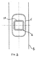
- a substantially flat rest surface 14 can be defined in the rung section, said surface being intended for support of the user's feet. This rest surface is such oriented that it is almost horizontal relative to the ground when the ladder is being used.
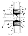
- Rung 1 further comprises engagement means 5, associated with the elongated body 19, adapted to lock the connecting portion 3 to the upright 4; this engagement means 5 advantageously comprises a coupling element 6 made by co-moulding directly on the connecting portion 3 of the elongated body 19.
- Upright 4 is substantially made up of an axial body 21, on which a plurality of connecting seatings 20 is provided, said seatings being for example obtained by a cutting operation at regular intervals along the axial body 21 itself; the upright is advantageously obtained by forming, and is made of a composite material, preferably fibreglass.
- the upright section as shown in Figs. 12 and 13, can be of any nature, provided it is adapted to withstand the stresses to which it is submitted.
- the coupling element 6 is made of a plastic material, preferably nylon.
- the coupling element 6 can be different, depending on whether said element is intended for being associated with the connecting portion 3 of rung 2 or with the connecting seating 20 of the upright 4.
- the coupling element 6 of same comprises locating extensions 7 operatively interacting with the connecting portion 3 of the elongated body 19.
- said locating extensions 7 essentially consist of excess plastic materials flowing through appropriate locating seats 11 formed on the connecting portion 3 of the elongated body 19.
- the coupling element 6 further comprises at least one installation housing 8 arranged to receive a mechanical fastener 9 operatively active between the coupling element 6 and the ladder upright 4.
- this mechanical fastener 9 is for example defined by a roundheaded screw; in addition, advantageously provided is the presence of a locking element 10, consisting of a screw anchor for example, the task of which is to prevent accidental disengagement of the mechanical fastener 9.
- the coupling element 6 has a section conforming in shape to a connecting housing 20 formed in the upright 4, so as to ensure a correct centering of rung 1 on the upright 4 during the assembling step; in addition, the coupling element 6 has a perimetric abutment region 12 intended to abut against the inner face of the upright 4. At the outer face of the upright 4, the coupling element 6 has a lead-in portion 13 close to the installation housing 8, so that the mechanical fastener 9 is correctly directed during the assembling step.
- the coupling element 6 is to be associated with the upright 4, it is co-moulded to a connecting seating 20 formed on the upright 4 by a cutting operation for example.
- the coupling element 6 is conformed in shape to the connecting seating 20, so as to ensure a precise assembling without plays that would make the ladder unsteady.
- the coupling element 6 further comprises a connecting projection 22 substantially shaped in a manner adapted to receive the connecting portion 3 of rung 2 inside it; internally of this connecting projection 22 there are locking ridges 23, consisting for example of indentations on the inner walls of the connecting projection 22, which are adapted to keep the connecting portion 3 of rung 2 in place; obviously, this connecting portion 3 is in this case provided with appropriate locking abutments 24 in engagement with the respective locking ridges 23.
- the coupling element 6 has installation housings 8 adapted to receive a mechanical fastener 9 equipped with a locking element 10, a screw provided with a screw anchor for example; in this way safe use and capability of being dismantled are ensured to the ladder.
- a ladder having at least two uprights 4 can be advantageously built.
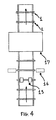
- the production line of the concerned ladder is organized in a continuous chain intended for construction of rungs 1 in accordance with the present invention and subsequent assembling of rungs 1 to uprights 4.
- Construction of the rungs starts from making a section member of composite material by extrusion or pultrusion, said section member being subsequently transversely cut so as to obtain rungs of a preestablished length; at this point the locating seats 11 are obtained, by drilling for example, at the line station 15 and the connecting portions 3 are also obtained by milling at the line station 16; finally, by co-moulding at the line station 17 the coupling element 6 is made on the connecting portion 3.
- Rungs 1 obtained from the preceding machining operations are subsequently handled along a continuous line in a first feed direction (see Fig. 5); uprights 4 coming from a second handling line defining a second feed direction transverse to the feed direction of rungs 1 converge towards the line carrying these rungs 1.
- association of the rungs with the assembling seatings formed on uprights 4 takes place and finally the assembly consisting of a pair of uprights 4 and a preestablished number of rungs is submitted to installation of the mechanical fasteners 9 between rungs 1 and uprights 4, at a screwing station 18 of the line, for example.
- the invention achieves important advantages.
- rungs are mechanically locked to the uprights by means of elements of easy installation and use, such as screws provided with screw anchors, assembling and disassembling of the ladder by the user is made very easy, if transportation of the ladder in a dismantled configuration is required in order to save room.
- the coupling element can be made of plastic material, such as nylon for example, the production costs can be greatly reduced as compared with those of the known art, in particular in those cases in which connecting accessories made of metal are required.
- the materials used, shapes and sizes can be of any nature and magnitude depending on requirements.
Landscapes
- Engineering & Computer Science (AREA)
- Mechanical Engineering (AREA)
- Ladders (AREA)
Priority Applications (2)
| Application Number | Priority Date | Filing Date | Title |
|---|---|---|---|
| EP00830133A EP1128020A1 (fr) | 2000-02-24 | 2000-02-24 | Echelle en matériau composite |
| US09/790,835 US20010017233A1 (en) | 2000-02-24 | 2001-02-22 | Rung ladder in composite material |
Applications Claiming Priority (1)
| Application Number | Priority Date | Filing Date | Title |
|---|---|---|---|
| EP00830133A EP1128020A1 (fr) | 2000-02-24 | 2000-02-24 | Echelle en matériau composite |
Publications (1)
| Publication Number | Publication Date |
|---|---|
| EP1128020A1 true EP1128020A1 (fr) | 2001-08-29 |
Family
ID=8175201
Family Applications (1)
| Application Number | Title | Priority Date | Filing Date |
|---|---|---|---|
| EP00830133A Withdrawn EP1128020A1 (fr) | 2000-02-24 | 2000-02-24 | Echelle en matériau composite |
Country Status (2)
| Country | Link |
|---|---|
| US (1) | US20010017233A1 (fr) |
| EP (1) | EP1128020A1 (fr) |
Cited By (1)
| Publication number | Priority date | Publication date | Assignee | Title |
|---|---|---|---|---|
| EP1700997A1 (fr) * | 2005-03-11 | 2006-09-13 | André Fournier | Echelle isolante électriquement et procédé de fabrication de ladite échelle |
Families Citing this family (7)
| Publication number | Priority date | Publication date | Assignee | Title |
|---|---|---|---|---|
| CN201056976Y (zh) * | 2007-06-29 | 2008-05-07 | 冷鹭浩 | 一种梯子及其梯蹬踏板 |
| US8800718B2 (en) * | 2008-12-30 | 2014-08-12 | Allred & Associates Inc. | Ultra lightweight segmented ladder/bridge system |
| US8448748B2 (en) | 2008-12-30 | 2013-05-28 | Allred & Associates, Inc. | Ultra lightweight segmented ladder/bridge system |
| US20130015016A1 (en) | 2011-07-16 | 2013-01-17 | Safe Rack Llc | Platform system |
| US10640983B2 (en) | 2016-03-23 | 2020-05-05 | Safe Rack Llc | Platform system |
| US10294720B2 (en) * | 2017-06-22 | 2019-05-21 | The Boeing Company | Ergonomic ladder |
| US11591802B1 (en) | 2020-02-28 | 2023-02-28 | Material Control, Inc. | Modular access system |
Citations (9)
| Publication number | Priority date | Publication date | Assignee | Title |
|---|---|---|---|---|
| US2932358A (en) * | 1956-12-04 | 1960-04-12 | Hopfeld Henry | Ladder construction and the method for making the same |
| GB1253589A (en) * | 1969-08-26 | 1971-11-17 | Glass Reinforced Engineered Ma | Ladder construction |
| AU7326974A (en) * | 1973-09-12 | 1976-03-18 | Fibre Glass Australia Pty Ltd | Fibre glass ladder |
| DE2827737A1 (de) * | 1977-07-25 | 1979-02-08 | Emerson Electric Co | Verfahren zur herstellung einer leiter und leiteraufbau |
| DE8802330U1 (de) * | 1988-02-23 | 1988-05-11 | Zarges Leichtbau Gmbh, 8120 Weilheim | Leiter |
| EP0359054A1 (fr) * | 1988-09-02 | 1990-03-21 | Akes Ag | Echelle constituée de montants reliés par des traverses |
| FR2673689A1 (fr) * | 1991-03-04 | 1992-09-11 | Rel Plastics Bvba | Element tubulaire, produits et assemblages tubulaires fabriques au moyen de cet element. |
| DE9409080U1 (de) * | 1994-06-03 | 1994-07-28 | Hans Holzhauer GmbH & Co. KG, 58638 Iserlohn | Stufenleiter |
| DE4440220A1 (de) * | 1993-11-11 | 1995-05-18 | Avanti Stigefabrik Aps | Verbindungsvorrichtung zur Verbindung der Sprossen einer Leiter mit den Holmen einer Leiter |
-
2000
- 2000-02-24 EP EP00830133A patent/EP1128020A1/fr not_active Withdrawn
-
2001
- 2001-02-22 US US09/790,835 patent/US20010017233A1/en not_active Abandoned
Patent Citations (9)
| Publication number | Priority date | Publication date | Assignee | Title |
|---|---|---|---|---|
| US2932358A (en) * | 1956-12-04 | 1960-04-12 | Hopfeld Henry | Ladder construction and the method for making the same |
| GB1253589A (en) * | 1969-08-26 | 1971-11-17 | Glass Reinforced Engineered Ma | Ladder construction |
| AU7326974A (en) * | 1973-09-12 | 1976-03-18 | Fibre Glass Australia Pty Ltd | Fibre glass ladder |
| DE2827737A1 (de) * | 1977-07-25 | 1979-02-08 | Emerson Electric Co | Verfahren zur herstellung einer leiter und leiteraufbau |
| DE8802330U1 (de) * | 1988-02-23 | 1988-05-11 | Zarges Leichtbau Gmbh, 8120 Weilheim | Leiter |
| EP0359054A1 (fr) * | 1988-09-02 | 1990-03-21 | Akes Ag | Echelle constituée de montants reliés par des traverses |
| FR2673689A1 (fr) * | 1991-03-04 | 1992-09-11 | Rel Plastics Bvba | Element tubulaire, produits et assemblages tubulaires fabriques au moyen de cet element. |
| DE4440220A1 (de) * | 1993-11-11 | 1995-05-18 | Avanti Stigefabrik Aps | Verbindungsvorrichtung zur Verbindung der Sprossen einer Leiter mit den Holmen einer Leiter |
| DE9409080U1 (de) * | 1994-06-03 | 1994-07-28 | Hans Holzhauer GmbH & Co. KG, 58638 Iserlohn | Stufenleiter |
Cited By (2)
| Publication number | Priority date | Publication date | Assignee | Title |
|---|---|---|---|---|
| EP1700997A1 (fr) * | 2005-03-11 | 2006-09-13 | André Fournier | Echelle isolante électriquement et procédé de fabrication de ladite échelle |
| FR2883029A1 (fr) * | 2005-03-11 | 2006-09-15 | Andre Fournier | Echelle isolante electriquement et procede de fabrication de ladite echelle |
Also Published As
| Publication number | Publication date |
|---|---|
| US20010017233A1 (en) | 2001-08-30 |
Similar Documents
| Publication | Publication Date | Title |
|---|---|---|
| US8033363B2 (en) | Method for producing a combo brace rail shield | |
| EP1128020A1 (fr) | Echelle en matériau composite | |
| US20020094228A1 (en) | Structural couplings and system | |
| JPH08509275A (ja) | 送電塔及びその他の大型構造物のための引出成形複合物継手システム | |
| US20020092248A1 (en) | Two-piece mullion reinforcement | |
| KR101763178B1 (ko) | 건축 비계용 안전발판 | |
| US7007903B2 (en) | Modular structures and connector assembly apparatus | |
| KR101937374B1 (ko) | 케이블트레이의 조립체 | |
| US10376047B1 (en) | Furniture frame system | |
| KR101850986B1 (ko) | 풀림 방지 너트 | |
| KR20110042655A (ko) | 케이블 트레이의 결합구조 | |
| JP2022545345A (ja) | ボードコネクターシステムとその手法 | |
| WO2013097865A1 (fr) | Segment annulaire pour bride de tour éolienne | |
| KR200451568Y1 (ko) | 케이블트레이 렁의 결합구조 | |
| EP2168218B1 (fr) | Élément de guidage de câble | |
| WO2006065048A1 (fr) | Dispositif de liaison de cordes avec une plaque d'appui, et echelle de corde comprenant de dispositif | |
| CN109812478A (zh) | 一种装配式管件 | |
| CN215126449U (zh) | 一种床架的连接结构 | |
| CN111424959B (zh) | 一种建筑用高空脚手架搭建连接件 | |
| CN216306403U (zh) | 一种插件 | |
| CN110541559A (zh) | 一种扣杆组件和爬梯 | |
| CN205531292U (zh) | 一种应用于脚手架上的踏板及脚手架 | |
| GB2476806A (en) | Modular ladder | |
| KR200311203Y1 (ko) | 핸드레일 | |
| KR200272475Y1 (ko) | 통신전주 |
Legal Events
| Date | Code | Title | Description |
|---|---|---|---|
| PUAI | Public reference made under article 153(3) epc to a published international application that has entered the european phase |
Free format text: ORIGINAL CODE: 0009012 |
|
| 17P | Request for examination filed |
Effective date: 20001018 |
|
| AK | Designated contracting states |
Kind code of ref document: A1 Designated state(s): AT BE CH CY DE DK ES FI FR GB GR IE IT LI LU MC NL PT SE |
|
| AX | Request for extension of the european patent |
Free format text: AL;LT;LV;MK;RO;SI |
|
| AKX | Designation fees paid |
Free format text: AT BE CH CY DE DK ES FI FR GB GR IE IT LI LU MC NL PT SE |
|
| 17Q | First examination report despatched |
Effective date: 20030220 |
|
| STAA | Information on the status of an ep patent application or granted ep patent |
Free format text: STATUS: THE APPLICATION IS DEEMED TO BE WITHDRAWN |
|
| 18D | Application deemed to be withdrawn |
Effective date: 20040221 |