EP1128054A2 - Dosierventilbaugruppe mit Druckausgleichvorrichtung für ein modulares Abgasrückführungsventil - Google Patents
Dosierventilbaugruppe mit Druckausgleichvorrichtung für ein modulares Abgasrückführungsventil Download PDFInfo
- Publication number
- EP1128054A2 EP1128054A2 EP01200543A EP01200543A EP1128054A2 EP 1128054 A2 EP1128054 A2 EP 1128054A2 EP 01200543 A EP01200543 A EP 01200543A EP 01200543 A EP01200543 A EP 01200543A EP 1128054 A2 EP1128054 A2 EP 1128054A2
- Authority
- EP
- European Patent Office
- Prior art keywords
- metering
- poppet
- pressure
- piston
- subassembly
- Prior art date
- Legal status (The legal status is an assumption and is not a legal conclusion. Google has not performed a legal analysis and makes no representation as to the accuracy of the status listed.)
- Withdrawn
Links
Images


Classifications
-
- F—MECHANICAL ENGINEERING; LIGHTING; HEATING; WEAPONS; BLASTING
- F02—COMBUSTION ENGINES; HOT-GAS OR COMBUSTION-PRODUCT ENGINE PLANTS
- F02M—SUPPLYING COMBUSTION ENGINES IN GENERAL WITH COMBUSTIBLE MIXTURES OR CONSTITUENTS THEREOF
- F02M26/00—Engine-pertinent apparatus for adding exhaust gases to combustion-air, main fuel or fuel-air mixture, e.g. by exhaust gas recirculation [EGR] systems
- F02M26/65—Constructional details of EGR valves
- F02M26/66—Lift valves, e.g. poppet valves
- F02M26/67—Pintles; Spindles; Springs; Bearings; Sealings; Connections to actuators
-
- F—MECHANICAL ENGINEERING; LIGHTING; HEATING; WEAPONS; BLASTING
- F02—COMBUSTION ENGINES; HOT-GAS OR COMBUSTION-PRODUCT ENGINE PLANTS
- F02M—SUPPLYING COMBUSTION ENGINES IN GENERAL WITH COMBUSTIBLE MIXTURES OR CONSTITUENTS THEREOF
- F02M26/00—Engine-pertinent apparatus for adding exhaust gases to combustion-air, main fuel or fuel-air mixture, e.g. by exhaust gas recirculation [EGR] systems
- F02M26/52—Systems for actuating EGR valves
- F02M26/53—Systems for actuating EGR valves using electric actuators, e.g. solenoids
-
- F—MECHANICAL ENGINEERING; LIGHTING; HEATING; WEAPONS; BLASTING
- F02—COMBUSTION ENGINES; HOT-GAS OR COMBUSTION-PRODUCT ENGINE PLANTS
- F02M—SUPPLYING COMBUSTION ENGINES IN GENERAL WITH COMBUSTIBLE MIXTURES OR CONSTITUENTS THEREOF
- F02M26/00—Engine-pertinent apparatus for adding exhaust gases to combustion-air, main fuel or fuel-air mixture, e.g. by exhaust gas recirculation [EGR] systems
- F02M26/13—Arrangement or layout of EGR passages, e.g. in relation to specific engine parts or for incorporation of accessories
- F02M26/40—Arrangement or layout of EGR passages, e.g. in relation to specific engine parts or for incorporation of accessories with timing means in the recirculation passage, e.g. cyclically operating valves or regenerators; with arrangements involving pressure pulsations
Definitions
- the present invention relates to exhaust gas recirculation valves for use with internal combustion engines.
- Exhaust gas recirculation (EGR) valves capture engine exhaust and recycle at least a portion of that captured exhaust gas into the combustion chamber of the engine to improve combustion.
- Exhaust gas is used since it is readily available and contains only a small amount of oxygen. Adding the exhaust gas to the air in the combustion chamber has the effect of lowering the combustion temperature below the point at which nitrogen combines with oxygen. Thus, exhaust gas recirculation increases fuel economy and reduces the level of undesirable emissions.
- EGR valves include an actuator and a metering base.
- the metering base includes a metering chamber having a metering port.
- the metering chamber has an end that is associated with the intake manifold or intake vacuum of the engine.
- the metering port is connected to a source of exhaust gas and provides a passageway for the flow of exhaust gas into the metering chamber.
- An elongate shaft extends contiguously in a longitudinal direction from the actuator, through an orifice in the metering base, into the metering chamber, and to the metering port.
- a metering poppet which is a plunger-shaped member, is disposed at the end of the shaft proximate to the metering port.
- the metering poppet In a default position, the metering poppet abuttingly engages or is disposed within the metering port, thereby sealing the metering port. In this default position, no exhaust gas enters the metering chamber through the metering port.
- the shaft is reciprocated to displace the metering poppet from engagement with the metering port thereby unsealing the metering port and allowing exhaust gas to flow through the metering port into the metering chamber and into the intake manifold of the engine.
- the reciprocal motion of the shaft and metering poppet selectively control the flow of exhaust gas into the intake air stream of the engine.
- Automotive engines operate under relatively high exhaust backpressure and pressure pulsations. These conditions of high backpressure and pressure pulsations can interfere with the operation of conventional EGR valves.
- the high amplitude pulsations can render the EGR valve uncontrollable by interfering with the motion of the shaft as the metering poppet comes into and out of sealing engagement with the metering port.
- the high amplitude pulsations increase the air loading on the relatively large surface area of the metering poppet.
- the increased air loading on the metering poppet increases the force necessary to reciprocate the shaft.
- the actuator must be designed to produce enough force to reciprocate the shaft under these conditions of high-amplitude pressure pulsations and increased air loading on the metering poppet.
- the actuator must be designed to produce more power than would be required to reciprocate the shaft absent the pressure pulsations and high back pressure.
- Automotive manufacturers are continually striving to decrease the cost, size and weight of components in order to conserve valuable and cramped engine compartment space, to decrease vehicle cost, and to decrease the overall weight of vehicles in the interest of fuel economy.
- An actuator that produces higher force comes with the undesirable consequences of increased size, weight, and cost.
- the present invention provides a pressure balancing metering subassembly for use with an actuator of a modular EGR valve.
- the invention comprises, in one form thereof, a metering base having a metering port and a metering chamber.
- An elongate poppet includes a first end normally disposed in sealing engagement with the metering port. The poppet is selectively reciprocated to disengage the first end from sealing engagement with the metering port to thereby fluidly connect the metering port with the metering chamber.
- Pressure balancing means balance a pressure at the first end of the poppet with a pressure at a second end of the poppet.
- An advantage of the present invention is that the effect of backpressure, pressure fluctuations, and pressure differentials upon reciprocation of the poppet is reduced.
- Yet another advantage of the present invention is that less force will be required to reciprocate the poppet.
- a still further advantage of the present invention is that less power will be required from an actuator to reciprocate the poppet.
- An even further advantage of the present invention is that it can be coupled to an actuator to form a modular EGR valve.
- Pressure balancing metering subassembly (PBMS) 10 includes piston 12, cylinder 14, elongate shaft 16, elongate poppet 18, seal 24 and base 26.
- Piston 12 is disposed within cylinder 14. As best shown in Fig. 2, piston 12 includes bottom surface 28 interconnected by cylindrical sidewall 29 to top surface 30. Bottom surface 28 is substantially cylindrical and is disposed around a bottom of sidewall 29. Top surface 30 is substantially cylindrical and disposed around a top of sidewall 29. Bottom surface 28 defines piston orifice 32. Piston 12 defines a conical inner surface 34 which tapers outwardly from bottom surface 28 to top surface 30. Piston orifice 32 extends axially through bottom surface 28, terminating at and opening into inner surface 34.
- Cylinder 14 is a cup-shaped member and includes a radially outward extending flange 42, top 43 and inner wall 44. Cylinder 14 is received substantially concentrically within bore 46 of base 26 until flange 42 contacts and seats upon base 26. Top 43 defines a shaft orifice 48 within which bearing seal 24 is disposed. Bottom surface 28 of piston 12 circumferentially engages inner wall 44 of cylinder 14 in an air and fluid tight manner. Top surface 30 of piston 12 circumferentially engages inner wall 44 of cylinder 14 proximate top 43 in an air and fluid tight manner. Pressure chamber 50 is defined between top surface 30, inner surface 34 of piston 12, inner wall 44 and top 43 of cylinder 14.
- Elongate shaft 16 includes a first end with a radially-outward extending shaft flange 60.
- Elongate shaft 16 extends axially from shaft flange 60 concentrically through bearing seal 24 and into pressure chamber 50.
- Bearing seal 24 is configured to seal shaft 16 and shaft orifice 48 in an air and fluid tight manner. Bearing seal 24 maintains this air and fluid tight interface between shaft 16 and shaft orifice 48 during reciprocal movement of shaft 16.
- Second end 62 of elongate shaft 16 is reciprocally disposed within pressure chamber 50 and defines an axial bore 64 therein.
- Spring 66 has one end disposed in engagement with flange 60 of elongate shaft 16, and the other end disposed in engagement with bearing seal 24. Spring 66 exerts an axially-directed force on each of flange 60 and bearing seal 24, thereby maintaining seal 24 in sealing disposition within shaft orifice 48 and biasing shaft 16 in a direction away from base 26.
- Elongate poppet 18 includes a plunger-shaped end 70 interconnected with a narrowed stem end 72 at its opposite end, and defines an axially extending cavity 74 therethrough.
- Stem end 72 extends through piston orifice 32 and is disposed within pressure chamber 50.
- Bottom surface 28 of piston 12 is tightly seated upon and engages poppet 18 in an air and fluid tight manner.
- Stem end 72 is received within axial bore 64 of and/or coupled to elongate shaft 16.
- reciprocation of poppet shaft 16 will, in turn, reciprocate poppet 18.
- Stem end 72 defines a radial orifice 78 which intersects cavity 74 thereby fluidly connecting cavity 74 with pressure chamber 50.
- Axial cavity 74 provides a passageway through which air flows from the area proximate plunger end 70 of elongate poppet 18 and into pressure chamber 50.
- Bearing seal 24 is disposed within shaft orifice 48 of cylinder 14. Elongate shaft 16 passes through bearing seal 24. Bearing seal 24 surrounds elongate shaft 16 in an air and fluid tight manner, thereby sealing pressure chamber 32. Bearing seal 24 maintains this seal during the reciprocal motion of elongate shaft 16 therein.
- Base 26 defines a metering port 80 (Fig. 3) and metering chamber 82.
- Metering port 80 is connected to a source of exhaust gas (not shown).
- Elongate poppet 18 extends through metering port 80.
- Plunger end 70 of elongate poppet 18 is disposed proximate to and is configured to sealingly engage metering port 80. Reciprocal motion of elongate shaft 16 is transferred to elongate poppet 18. Such reciprocal motion will bring plunger end 70 of elongate poppet 18 into and out of sealing engagement with metering port 80, thereby selectively opening and closing metering port 80.
- Plunger end 70 in a default position is disposed in sealing engagement with metering port 80, thereby preventing any flow of exhaust gas into metering chamber 82.
- Elongate poppet 18 is selectively reciprocated out of sealing engagement with metering port 80 to allow exhaust gas to flow therethrough and into metering chamber 82.
- Base 26 further includes mounting bores 86a and 86b.
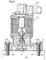
- modular EGR valve 100 includes pressure balanced metering subassembly (PBMS) 10 and modular actuator subassembly 90.
- Actuator subassembly 90 is coupled to PBMS 10 and selectively reciprocates elongate shaft 16 of PBMS 10 which, in turn, reciprocates plunger end 70 of elongate poppet 18 into and out of sealing engagement with metering port 80.
- exhaust gas is selectively allowed to flow through metering port 80 and into metering chamber 82.
- Fasteners such as, for example, eyelets 95a and 95b are used to couple PBMS 10 to actuator subassembly 90.
- Fasteners such as, for example, bolts 102a and 102b are used to couple the modular EGR valve 100 to engine 104.
- (PBMS) 10 is coupled to actuator subassembly 90, which is configured to selectively reciprocate elongate shaft 16 and, in turn, elongate poppet 18, thereby sealing and unsealing metering port 80.
- Exhaust gas will exert a pressure against plunger end 70 of elongate poppet 18.
- This pressure will include pulsations between a high pressure and a lower pressure. Any pressure and transient pressure surges in the area proximate plunger 70 will be transferred into pressure chamber 50 through cavity 74, thereby equalizing the pressure acting on plunger 70 with the pressure in pressure chamber 50.
- the same pressure acting upon plunger 70 acts upon inner surface 34 of piston 12. Therefore, reciprocation of elongate shaft 16 and, in turn, elongate poppet 18 is accomplished without requiring the force necessary to overcome the back pressure and pressure pulsations present at plunger 70.
- PBMS 10 is coupled to actuator subassembly 90.
- PBSM 10 can be alternately configured to be coupled or otherwise operably associated with a variously configured actuator subassemblies.
Landscapes
- Engineering & Computer Science (AREA)
- Chemical & Material Sciences (AREA)
- Combustion & Propulsion (AREA)
- Mechanical Engineering (AREA)
- General Engineering & Computer Science (AREA)
- Exhaust-Gas Circulating Devices (AREA)
- Lift Valve (AREA)
- Multiple-Way Valves (AREA)
Applications Claiming Priority (2)
| Application Number | Priority Date | Filing Date | Title |
|---|---|---|---|
| US18453000P | 2000-02-24 | 2000-02-24 | |
| US184530P | 2000-02-24 |
Publications (2)
| Publication Number | Publication Date |
|---|---|
| EP1128054A2 true EP1128054A2 (de) | 2001-08-29 |
| EP1128054A3 EP1128054A3 (de) | 2002-08-28 |
Family
ID=22677284
Family Applications (1)
| Application Number | Title | Priority Date | Filing Date |
|---|---|---|---|
| EP01200543A Withdrawn EP1128054A3 (de) | 2000-02-24 | 2001-02-16 | Dosierventilbaugruppe mit Druckausgleichvorrichtung für ein modulares Abgasrückführungsventil |
Country Status (2)
| Country | Link |
|---|---|
| US (1) | US6435168B1 (de) |
| EP (1) | EP1128054A3 (de) |
Cited By (1)
| Publication number | Priority date | Publication date | Assignee | Title |
|---|---|---|---|---|
| WO2015055568A1 (de) * | 2013-10-14 | 2015-04-23 | Continental Automotive Gmbh | Ventil |
Families Citing this family (8)
| Publication number | Priority date | Publication date | Assignee | Title |
|---|---|---|---|---|
| US6871699B1 (en) | 1999-08-16 | 2005-03-29 | Delphi Technologies, Inc. | Engine coolant conduit with integral alternator and exhaust gas recirculation valve |
| US6759934B2 (en) * | 2000-09-11 | 2004-07-06 | Delphi Technologies, Inc. | Proportionally-controllable solenoid actuator |
| GB0123773D0 (en) | 2001-10-03 | 2001-11-21 | Delphi Tech Inc | Metering valve arrangement |
| US6715475B2 (en) | 2001-10-26 | 2004-04-06 | Siemens Vdo Automotive, Incorporated | Exhaust gas recirculation valve |
| US6866063B2 (en) | 2002-09-06 | 2005-03-15 | Delphi Technologies, Inc. | Low leak pressure control actuator |
| US6871668B2 (en) * | 2003-01-13 | 2005-03-29 | Delphi Technologies Inc. | Variable force actuator with a double needle poppet assembly |
| AU2004209419B2 (en) * | 2003-01-31 | 2010-11-25 | Lim Technology Llc | Pneumatically actuated valve for internal combustion engines |
| CN109139308A (zh) * | 2015-03-19 | 2019-01-04 | 常州科普动力机械有限公司 | 内燃机用egr止通阀的工作方法 |
Family Cites Families (8)
| Publication number | Priority date | Publication date | Assignee | Title |
|---|---|---|---|---|
| US5255659A (en) * | 1992-09-28 | 1993-10-26 | Ford Motor Company | Pressure balanced exhaust gas recirculation valve |
| US6178956B1 (en) * | 1996-05-20 | 2001-01-30 | Borgwarner Inc. | Automotive fluid control system with pressure balanced solenoid valve |
| DE19721993A1 (de) * | 1997-05-26 | 1998-12-17 | Ammermann Klaus Dr | Abgasrückführungsventil mit Druckkompensation |
| DE19824103A1 (de) * | 1998-05-29 | 1999-12-02 | Pierburg Ag | Abgassteuerventil |
| DE50003439D1 (de) * | 1999-02-02 | 2003-10-02 | Kayser Automotive Systems Gmbh | Gasführungseinrichtung |
| US6217001B1 (en) * | 1999-06-29 | 2001-04-17 | Delphi Technologies, Inc. | Pressure balanced gas valve |
| DE19935483A1 (de) * | 1999-07-28 | 2001-02-01 | Delphi Tech Inc | Steuerventil zur Abgasrückführung |
| DE19936657A1 (de) * | 1999-08-04 | 2001-02-15 | Mannesmann Vdo Ag | Steuerventil |
-
2000
- 2000-11-22 US US09/721,225 patent/US6435168B1/en not_active Expired - Fee Related
-
2001
- 2001-02-16 EP EP01200543A patent/EP1128054A3/de not_active Withdrawn
Cited By (1)
| Publication number | Priority date | Publication date | Assignee | Title |
|---|---|---|---|---|
| WO2015055568A1 (de) * | 2013-10-14 | 2015-04-23 | Continental Automotive Gmbh | Ventil |
Also Published As
| Publication number | Publication date |
|---|---|
| US6435168B1 (en) | 2002-08-20 |
| EP1128054A3 (de) | 2002-08-28 |
Similar Documents
| Publication | Publication Date | Title |
|---|---|---|
| US6247461B1 (en) | High flow gas force balanced EGR valve | |
| US8955501B2 (en) | PCV valve mounting structures | |
| US6182646B1 (en) | Electromechanically actuated solenoid exhaust gas recirculation valve | |
| US6217001B1 (en) | Pressure balanced gas valve | |
| EP2182185B1 (de) | Motorgehäuseentlüftungssystem für Brennkraftmaschine | |
| US20040211400A1 (en) | Recycling circuit for crankcase gases of an internal combustion engine | |
| US8424499B2 (en) | Pneumatic system for controlling the valves of an internal combustion engine | |
| US6435168B1 (en) | Pressure balancing metering subassembly for use with a modular EGR valve | |
| EP0900931A2 (de) | Abgasrückführungsventil | |
| JP2004522036A (ja) | 燃焼エンジンにおける圧力制御のためのバルブデバイスおよびそのような圧力制御のための方法 | |
| CN105121831A (zh) | 活塞泵、特别是燃料高压泵 | |
| AU2005200885B2 (en) | Pressure reducing valve | |
| US6497225B1 (en) | EGR metering subassembly including a gas arrestor | |
| US20030042450A1 (en) | Force-balanced gas control valve | |
| US10480366B2 (en) | Throttled PCV system for an engine | |
| US20010048093A1 (en) | Control valve | |
| EP0900934B1 (de) | Kraftstoffzufuhreinrichtung | |
| EP1398494B1 (de) | Abgasrückführventil mit niedrigem Luftwiderstand | |
| JPS6116219A (ja) | 内燃機関のブロ−バイガス流量制御弁 | |
| US6725661B1 (en) | Valve device | |
| JP3620888B2 (ja) | 多段位置決めが可能なアクチュエータ | |
| CN114810373B (zh) | 用于重型发动机的集成辅助空气系统 | |
| JP4594254B2 (ja) | Pcvバルブ | |
| JPH10103166A (ja) | 排気ガス再循環装置用バルブ | |
| JPS6116220A (ja) | 内燃機関のオイル消費低減装置 |
Legal Events
| Date | Code | Title | Description |
|---|---|---|---|
| PUAI | Public reference made under article 153(3) epc to a published international application that has entered the european phase |
Free format text: ORIGINAL CODE: 0009012 |
|
| AK | Designated contracting states |
Kind code of ref document: A2 Designated state(s): AT BE CH CY DE DK ES FI FR GB GR IE IT LI LU MC NL PT SE TR |
|
| AX | Request for extension of the european patent |
Free format text: AL;LT;LV;MK;RO;SI |
|
| PUAL | Search report despatched |
Free format text: ORIGINAL CODE: 0009013 |
|
| AK | Designated contracting states |
Kind code of ref document: A3 Designated state(s): AT BE CH CY DE DK ES FI FR GB GR IE IT LI LU MC NL PT SE TR |
|
| AX | Request for extension of the european patent |
Free format text: AL;LT;LV;MK;RO;SI |
|
| 17P | Request for examination filed |
Effective date: 20030228 |
|
| AKX | Designation fees paid |
Designated state(s): DE FR GB |
|
| STAA | Information on the status of an ep patent application or granted ep patent |
Free format text: STATUS: THE APPLICATION IS DEEMED TO BE WITHDRAWN |
|
| 18D | Application deemed to be withdrawn |
Effective date: 20040901 |