EP1128080B1 - Vierradantrieb- Einschaltvorrichtung - Google Patents
Vierradantrieb- Einschaltvorrichtung Download PDFInfo
- Publication number
- EP1128080B1 EP1128080B1 EP01102623A EP01102623A EP1128080B1 EP 1128080 B1 EP1128080 B1 EP 1128080B1 EP 01102623 A EP01102623 A EP 01102623A EP 01102623 A EP01102623 A EP 01102623A EP 1128080 B1 EP1128080 B1 EP 1128080B1
- Authority
- EP
- European Patent Office
- Prior art keywords
- dog
- shaft
- drive train
- piston
- train according
- Prior art date
- Legal status (The legal status is an assumption and is not a legal conclusion. Google has not performed a legal analysis and makes no representation as to the accuracy of the status listed.)
- Expired - Lifetime
Links
- 239000012530 fluid Substances 0.000 claims description 11
- 240000005002 Erythronium dens canis Species 0.000 claims description 3
- 230000000284 resting effect Effects 0.000 claims 1
- 241000282472 Canis lupus familiaris Species 0.000 description 58
- 230000007246 mechanism Effects 0.000 description 8
- 238000000926 separation method Methods 0.000 description 4
- 230000005540 biological transmission Effects 0.000 description 3
- 230000003247 decreasing effect Effects 0.000 description 1
- 230000001419 dependent effect Effects 0.000 description 1
Images

Classifications
-
- F—MECHANICAL ENGINEERING; LIGHTING; HEATING; WEAPONS; BLASTING
- F16—ENGINEERING ELEMENTS AND UNITS; GENERAL MEASURES FOR PRODUCING AND MAINTAINING EFFECTIVE FUNCTIONING OF MACHINES OR INSTALLATIONS; THERMAL INSULATION IN GENERAL
- F16D—COUPLINGS FOR TRANSMITTING ROTATION; CLUTCHES; BRAKES
- F16D11/00—Clutches in which the members have interengaging parts
- F16D11/14—Clutches in which the members have interengaging parts with clutching members movable only axially
-
- F—MECHANICAL ENGINEERING; LIGHTING; HEATING; WEAPONS; BLASTING
- F16—ENGINEERING ELEMENTS AND UNITS; GENERAL MEASURES FOR PRODUCING AND MAINTAINING EFFECTIVE FUNCTIONING OF MACHINES OR INSTALLATIONS; THERMAL INSULATION IN GENERAL
- F16D—COUPLINGS FOR TRANSMITTING ROTATION; CLUTCHES; BRAKES
- F16D11/00—Clutches in which the members have interengaging parts
- F16D2011/006—Locking or detent means, i.e. means to keep the clutch in engaged condition
Definitions
- This invention relates to an actuating system for a clutch, and in particular to an actuating system for a clutch which engages and disengages drive to the front axle of a vehicle, such as a tractor.
- Utility vehicles such as agricultural and industrial tractors often comprise a front axle, which may be driven. Some vehicles have permanent four wheel drive, but most vehicles are provided with means to selectively engage and disengage drive to the front axle. Generally it is considered preferable to provide for disengagement of drive to the front axle so that the vehicle can be driven on roads and other surfaces where there is a high level of grip between the tyres and the surface without torque wind up occurring in the drive-line.
- the front wheels Whilst it is generally undesirable to drive on roads and the like with drive to the front axle engaged, in certain scenarios it is preferable to engage drive to the front wheels. For instance, by engaging drive to the front axle during braking of the vehicle, the braking efficiency of the vehicle is increased, and hence its stopping distance is decreased. It is therefore common for four-wheel drive tractors to be equipped with means to selectively engage and disengage drive to the front axle, and control means to control the engagement of drive to the front axle.
- the control means may disengage drive to the front axle when the speed of the vehicle exceeds a certain threshold (indicative of the vehicle travelling on a road or the like), and it may also engage drive to the front axle on actuation of the brakes, disengaging drive on release of the brakes.
- One type of mechanism for engaging and disengaging drive the front axle consists of a wet clutch, which be engaged and disengaged hydraulically.
- the engagement and disengagement of such wet clutches can be controlled electronically, and as such this type of arrangement is particulary suitable for the task.
- this type of arrangement is relatively complex and costly.
- Another type of mechanism for engaging and disengaging drive to the front axle consists of a dog clutch, the dogs being engaged by means of a spring, and disengaged by hydraulic pressures. This arrangement is satisfactory, but the time taken for the dogs to disengage is subject to variation due to the load on the front axle. This means that if a tractor is equipped with a front loader, or is carrying a heavy implement on the front linkage, drive to the front axle will not disengage as quickly as it would if the loader or implement were not present.
- Another type of mechanism for engaging and disengaging drive to the from axle again consists of a dog clutch.
- the dog teeth have flanks inclined at an angle of approximately 20 degrees so that a separation force is automatically generated which tends to disengage the dog teeth if no axial force is applied to hold the dog teeth in engagement.
- Springs also provide an additional separation force.
- the dog teeth are held in engagement by toggle members. Engagement is by hydraulic pressure, release of hydraulic pressure allowing the springs, together with the angled faces of the dog teeth, to disengage the dog clutch.
- This mechanism ensures rapid engagement and disengagement of drive to the front axle. However, where the brakes are being applied and released rapidly and successively this results in the rapid and successive engagement and disengagement of drive to the front axle.
- Each time the dog clutch is engaged and disengaged a load is placed on the drive line which causes the driver to experience a jolt.
- US-A-4307795 discloses a cam operated clutch mechanism for a lawn mower in which an input shaft is coupled to an output shaft via a sliding dog coupler. This reference also refers to the use of dog teeth with an inclination of about six degrees allowing disengagement of the dog teeth even when under load although such tooth angles are said to shorten tooth life.
- the objective of the invention can be achieved by providing dog teeth having flanks inclined at an angle which falls within a particular range. Within the range a separation force is automatically generated which tends to disengage the dog teeth if no axial force is applied to hold the dog teeth in engagement, but the result is relatively slow disengagement of the dog clutch as opposed to almost instantaneous disengagement.
- an increased load is placed on the front axle, the load on the input and output shafts, and hence the separating load generated by the dog teeth, is increased.
- the invention thus provides a drive train comprising a first shaft and a second shaft and a dog clutch for selectively engaging and disengaging drive between the said shafts, the dog clutch comprising first and second toothed dog members, wherein the first and second dog members are arranged for relative axial movement therebetween to engage and disengage drive between the said shafts, and wherein at least one of the flanks of the or each dog tooth is inclined at an angle ⁇ said angle ⁇ being in the range 5 to 10 degrees, the drive train being characterised in that locking means are provided to lock the said dog members in the engaged position, in that the locking means comprises a locking member mounted in the shaft mounting the dog members for movement between locked and unlocked positions, and an actuator is provided to move the locking member between the two positions, wherein in the locked position a portion of the locking member protrudes beyond the outer surface of the said shaft and engages with the slidably mounted dog member preventing axial movement thereof to lock the dog clutch in engagement, and in that in the unlocked position the locking member does not engage with the dog member thereby
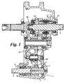
- a tractor front wheel drive train 1 comprising a transmission case 2, an input shaft 3 rotatably mounted in the case 2 by means of bearings 31, 32, and an output shaft 5 rotatably mounted in the case 2 by means of bearings 4, 6.
- the input shaft 3 carries a first gear wheel 40, and through gears 41 and 42 transmits torque to a first dog member 7 having gear teeth around the circumference thereof which mesh with a gear 42
- the dog member 7 is mounted on the shaft 5 to permit relative rotation therebetween.
- the dog member 7 forms half of a dog clutch 10, the other half of the dog clutch comprising a second dog member having an internally splined collar 9 which is slidably mounted on the externally splined output shaft 5.
- the opposing end faces of the dog members 7 and 9 each comprise at least one dog tooth, thereby transmitting drive from the input shaft to the output shaft when the dog clutch 10 is engaged.
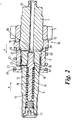
- FIG. 2 the dog teeth 11 and 12 of the dog members 7 and 9 respectively are engaged.
- a piston 13 is slidably mounted inside a bore 14 in the output shaft 5.
- a spring 15 surrounds a shaft portion 16 of the piston, the ends of the spring engaging at one end with a stop 17 and at the other end with a step portion 18 of the piston 13, the spring 15 biasing the piston in the direction of arrow X.
- the piston 13 comprises a cam surface 19 which operates a locking pin 20.
- the pin 20 rests on the surface 21 of the piston 13.
- the piston, 13 moves with respect to the cylinder 5, the pin 20 engages. with the cam surface 19 and is moved radially outwards.
- the piston 13 brings into the position shown in Figure 2, where the pin 20 is held between the surfaces 23 and 24 of the collar 9 and piston 13 respectively.
- Movement from the engaged position shown in Figure 2 to the disengaged position shown in Figure 3 is achieved by introducing hydraulic fluid into the bore 25 in the output shaft 5.
- Hydraulic fluid pressure acts on the end face 28 of the piston 13 and, when the fluid pressure is greater than the force exerted by the spring 15, the piston moves in the direction Y. Movement of the piston 13 allows the pin 20 to move radially inwards.
- the introduction of hydraulic fluid through the bore 25 fills the bore 26 with hydraulic fluid.
- the collar 9 has a step portion 27, which forms a chamber 29.
- the hydraulic fluid pressure is sufficient to overcome the force generated by the spring 30, the collar 9 moves in the direction Y and the dog teeth 11, 12 disengage, as shown in Figure 3.
- the longitudinal axis of the pin 20 lies in the path of the angled surface 22, movement of the collar 9 in the Y direction thereby ensuring the retraction of said pin.
- the dog teeth 11 and 12 have angled flanks inclined at an angle of approximately 7 degrees so that a separation force is automatically generated, which tends to disengage the dog teeth if no axial force is applied to hold the dog teeth in engagement.
- the shallow angle of approximately 7 degrees means that when disengagement of the clutch 10 is initiated, the combined force of the hydraulic pressure in chamber 29 and the axial force generated by the engaging dog teeth, does not result in instantaneous disengagement of the dog clutch 10 when a significant torque is applied, rather a short time interval will elapse as the dog clutch disengages.
- the invention thereby overcomes the problems associated with dog clutch actuation systems where the flanks of the dog teeth are parallel, i.e. the dogs do not disengage quickly enough (certain load conditions increasing the time taken for the dogs to disengage), and the problems associated with dog clutch actuation systems where the flanks of the dog teeth have steep angles which results in noise and jolting of the drive line and hence the vehicle.
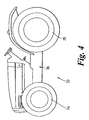
- a tractor 33 comprising front and rear driven wheels 34, 35, and a transmission 36 comprising a drive train according to the invention to transmit drive to the front axle.
Landscapes
- Engineering & Computer Science (AREA)
- General Engineering & Computer Science (AREA)
- Mechanical Engineering (AREA)
- Arrangement And Driving Of Transmission Devices (AREA)
- Mechanical Operated Clutches (AREA)
- Arrangement And Mounting Of Devices That Control Transmission Of Motive Force (AREA)
Claims (11)
- Antrieb mit einer ersten Welle (3) und einer zweiten Welle (5) und einer Klauenkupplung (10) zum selektiven Ein- und Ausrücken des Antriebs zwischen den Wellen, wobei die Klauenkupplung erste und zweite gezahnte Klauen (11, 12) aufweist, die zum Ein- und Ausrücken des Antriebs zwischen den Wellen (3, 5) zueinander axial beweglich angeordnet sind, und wobei mindestens eine Flanke der oder jeder Klaue (11, 12) geneigt in einem Winkel α in einem Bereich zwischen 5° und 10° angeordnet ist, dadurch gekennzeichnet, dass Mittel (19, 20) zum Blockieren der Klauen in der eingerückten Stellung vorgesehen sind, dass die Mittel ein Element (20) für die Blockierung der Axialbewegung zwischen der eingerückten und der ausgerückten Stellung auf der die Klauen (11, 12) tragenden Welle (5) aufweisen, und dass ein Aktuator (13, 19, 28) zum Bewegen des Elements (20) zwischen den beiden Stellungen vorgesehen ist, wobei in der blockierten Stellung ein Teil des Elements (20) über die äußere Oberfläche der Welle (5) vorsteht und mit der gleitend angeordneten Klaue (9, 12) in Kontakt kommt, so dass deren Axialbewegung bei eingerückter Kupplung verhindert ist, und dass das Element (20) in der unblockierten Stellung mit der Klaue (9, 12) nicht in Kontakt kommt, so dass die Axialbewegung relativ zu der Welle (5) in die ausgerückte Stellung der Klauenkupplung (10) möglich ist.
- Ein Antrieb nach Anspruch 1, dadurch gekennzeichnet, dass die Klauen (11, 12) auf einer (5) der Wellen (3, 5) angeordnet sind, und dass mindestens eine Klaue (12) gleitend auf der Welle gelagert ist.
- Ein Antrieb nach Anspruch 1 oder 2, dadurch gekennzeichnet, dass Mittel zum Ausrücken in Form eines durch ein Fluid betätigbaren Aktuators (26, 27, 29) vorgesehen sind, um eine Klaue (12) axial zu bewegen und damit die Klauen außer Eingriff zu bringen.
- Ein Antrieb nach einem der vorangehenden Ansprüche, dadurch gekennzeichnet, dass ein Mittel (30) zum Beaufschlagen der Zähne der Klauen (11, 12) in Eingriffsrichtung vorgesehen ist.
- Ein Antrieb nach Anspruch 4, dadurch gekennzeichnet, dass das Mittel eine Feder (30) aufweist.
- Ein Antrieb nach Anspruch 3, dadurch gekennzeichnet, dass der Aktuator zum Betätigen der Klaue einen gleitend an der die Klauen (11, 12) tragenden Welle (5) gelagerten Kolben (9) aufweist, wobei der Kolben eine Stufe (27) aufweist, die mit der Welle (5) eine hydraulisch beaufschlagbare Kammer (29) bildet, um den Kolben zum Ausrücken der Klauenkupplung (10) axial auf der Welle zu verschieben.
- Ein Antrieb nach einem der Ansprüche 1 bis 6, dadurch gekennzeichnet, dass der Aktuator zum Betätigen des Elements einen in einer Bohrung (14) der Welle (5) angeordneten Kolben (13) aufweist, der zwischen einer blockierenden und einer nicht-blockierenden Stellung bewegbar ist, und wobei der Kolben eine Nockenfläche (19) aufweist, auf der sich das Element (20) abstützt und der Nockenfläche während der Axialbewegung des Kolbens (13) folgt, um das Element (20) zwischen der blockierenden und einer nicht-blockierenden Stellung zu bewegen.
- Ein Antrieb nach Anspruch 7, dadurch gekennzeichnet, dass ein Mittel (15) zum Beaufschlagen des Kolbens (13) in die blockierende Stellung vorgesehen ist.
- Ein Antrieb nach Anspruch 7, dadurch gekennzeichnet, dass das eine Ende der Bohrung (14) für die Zufuhr eines unter Druck stehenden Fluids offen (25) ausgebildet ist, wobei die Zufuhr des Fluids den Kolben (13) gegen das Mittel (15) in die nicht-blockierende Stellung beaufschlagt.
- Ein Antrieb nach Anspruch 9, dadurch gekennzeichnet, dass die Welle (3) eine Bohrung (25) aufweist, durch die ein unter Druck stehendes Fluid eingebracht werden kann um die Klauenkupplung (10) auszurücken.
- Ein Schlepper mit vorderen und hinteren Antriebswellen (34, 35), dadurch gekennzeichnet, dass ein Antrieb nach einigen der Ansprüche 1 bis 10 vorgesehen ist, wobei der Antrieb der vorderen Antriebswellen (34) durch das Einrücken oder Ausrücken der Klauenkupplung (10) selektiv zuschaltbar ist.
Applications Claiming Priority (2)
| Application Number | Priority Date | Filing Date | Title |
|---|---|---|---|
| GB0004139 | 2000-02-23 | ||
| GB0004139A GB2359596B (en) | 2000-02-23 | 2000-02-23 | Four wheel drive engagement device |
Publications (2)
| Publication Number | Publication Date |
|---|---|
| EP1128080A1 EP1128080A1 (de) | 2001-08-29 |
| EP1128080B1 true EP1128080B1 (de) | 2007-08-22 |
Family
ID=9886157
Family Applications (1)
| Application Number | Title | Priority Date | Filing Date |
|---|---|---|---|
| EP01102623A Expired - Lifetime EP1128080B1 (de) | 2000-02-23 | 2001-02-07 | Vierradantrieb- Einschaltvorrichtung |
Country Status (3)
| Country | Link |
|---|---|
| EP (1) | EP1128080B1 (de) |
| DE (1) | DE60130049T2 (de) |
| GB (1) | GB2359596B (de) |
Cited By (1)
| Publication number | Priority date | Publication date | Assignee | Title |
|---|---|---|---|---|
| CN105339202A (zh) * | 2013-03-15 | 2016-02-17 | 艾里逊变速箱公司 | 变速器旁通离合器 |
Families Citing this family (4)
| Publication number | Priority date | Publication date | Assignee | Title |
|---|---|---|---|---|
| GB2389249A (en) * | 2002-05-29 | 2003-12-03 | Mark Colin Porter | Electricity generating abstract |
| DE102010029488B4 (de) | 2010-05-31 | 2024-02-29 | Zf Friedrichshafen Ag | Betätigungsvorrichtung einer rotierenden, schaltbaren mechanischen Verbindung |
| JP6475190B2 (ja) * | 2016-05-25 | 2019-02-27 | 株式会社スギノマシン | 傾動装置 |
| GB2602504B (en) * | 2021-01-05 | 2023-03-01 | Concentric Birmingham Ltd | Hybrid pump apparatus |
Family Cites Families (10)
| Publication number | Priority date | Publication date | Assignee | Title |
|---|---|---|---|---|
| GB1146591A (en) * | 1965-06-09 | 1969-03-26 | Sunbeam Electric Ltd | Improvements in or relating to clutch mechanisms for mechanical hand tools |
| DE2523953C3 (de) * | 1975-05-30 | 1980-05-14 | Dr.Ing.H.C. F. Porsche Ag, 7000 Stuttgart | Synchronisiereinrichtung, insbesondere für Geschwindigkeitswechselgetriebe von Kraftfahrzeugen |
| US4307795A (en) * | 1980-03-10 | 1981-12-29 | The J. B. Foote Foundry Co. | Cam shift mechanism |
| FR2614864B1 (fr) * | 1987-05-04 | 1991-05-10 | Bobard Jeune Sa Ets | Procede de correction de la trajectoire d'un vehicule se deplacant en travers d'une pente |
| GB8926365D0 (en) * | 1989-11-22 | 1990-01-10 | Perry Forbes G D | Toothed coupling |
| JP2573802Y2 (ja) * | 1990-07-27 | 1998-06-04 | 自動車電機工業株式会社 | アクチュエータ |
| DE4138917A1 (de) * | 1991-11-27 | 1992-11-19 | Daimler Benz Ag | Axial ein- und ausrueckbare klauenkupplung |
| JP3457789B2 (ja) * | 1996-01-12 | 2003-10-20 | 三菱マテリアルシ−エムアイ株式会社 | クラッチ付き駆動装置 |
| DE19848253B4 (de) * | 1998-02-09 | 2007-05-31 | Zf Sachs Ag | Kupplungseinrichtung mit einem an einer Schwungmasse vorgesehenen Aufnehmer für einen Mitnehmer |
| US6112873A (en) * | 1999-05-10 | 2000-09-05 | Case Corporation | Anti-backlash dog type clutch |
-
2000
- 2000-02-23 GB GB0004139A patent/GB2359596B/en not_active Expired - Fee Related
-
2001
- 2001-02-07 DE DE2001630049 patent/DE60130049T2/de not_active Expired - Lifetime
- 2001-02-07 EP EP01102623A patent/EP1128080B1/de not_active Expired - Lifetime
Non-Patent Citations (1)
| Title |
|---|
| None * |
Cited By (3)
| Publication number | Priority date | Publication date | Assignee | Title |
|---|---|---|---|---|
| CN105339202A (zh) * | 2013-03-15 | 2016-02-17 | 艾里逊变速箱公司 | 变速器旁通离合器 |
| CN105339202B (zh) * | 2013-03-15 | 2017-11-28 | 艾里逊变速箱公司 | 变速器旁通离合器 |
| US10145471B2 (en) | 2013-03-15 | 2018-12-04 | Allison Transmission, Inc. | Variator bypass clutch |
Also Published As
| Publication number | Publication date |
|---|---|
| GB2359596A (en) | 2001-08-29 |
| DE60130049D1 (de) | 2007-10-04 |
| DE60130049T2 (de) | 2007-12-27 |
| GB2359596B (en) | 2004-06-09 |
| GB0004139D0 (en) | 2000-04-12 |
| EP1128080A1 (de) | 2001-08-29 |
Similar Documents
| Publication | Publication Date | Title |
|---|---|---|
| DE3877137T2 (de) | Kraftuebertragungseinrichtung. | |
| US4280583A (en) | Automatic differential control apparatus | |
| US4462271A (en) | Automatic differential control apparatus | |
| US9784355B1 (en) | Axle disconnect and differential lock combination | |
| US9073432B2 (en) | Disconnectable driveline for all-wheel drive vehicle | |
| US6079535A (en) | Transfer case with disconnectable transfer clutch | |
| US6634446B2 (en) | Multi-wheel-drive vehicle with a front transaxle device | |
| US8622868B2 (en) | Electronic differential lock assembly | |
| US20120238394A1 (en) | Disconnecting rear drive axle for longitudinally arranged powertrains | |
| EP1077846B1 (de) | Bremsvorrichtung und bremsmittel | |
| EP1128080B1 (de) | Vierradantrieb- Einschaltvorrichtung | |
| US5465820A (en) | Clutch actuating device for use in a vehicle drivetrain subassembly | |
| EP1522767B1 (de) | Formschlüssige Kupplung für Verteilergetriebe und Ausgleichsgetriebe für Kraftfahrzeuge | |
| EP0093813B1 (de) | Fahrzeugdifferential und Getriebesystem | |
| CN100558576C (zh) | 用于车辆传动系统的驱动系统以及包括该驱动系统的车辆 | |
| EP2181011B1 (de) | Fahrzeuggetriebe mit antriebsunterbrechungssystem und -vorrichtung | |
| US4509626A (en) | Hydraulically actuated high torque, quick engagement clutch assembly | |
| US4050328A (en) | Four-wheel drive vehicle with drive transfer gear assembly | |
| EP0928374B1 (de) | Automatisch gesteuerte kupplung | |
| US5067935A (en) | Interaxle differential | |
| KR102582845B1 (ko) | 작업 차량 및 작업 차량용 구동추출장치 | |
| DE102008001889A1 (de) | Bremsbares Verteilergetriebe | |
| WO2007044478A1 (en) | Multiplexed hydraulic control for a two-coupling all-wheel drive system | |
| EP0248005B1 (de) | Kraftübertragungskopplung | |
| JPH0433134Y2 (de) |
Legal Events
| Date | Code | Title | Description |
|---|---|---|---|
| PUAI | Public reference made under article 153(3) epc to a published international application that has entered the european phase |
Free format text: ORIGINAL CODE: 0009012 |
|
| AK | Designated contracting states |
Kind code of ref document: A1 Designated state(s): DE FR IT TR Kind code of ref document: A1 Designated state(s): AT BE CH CY DE DK ES FI FR GB GR IE IT LI LU MC NL PT SE TR |
|
| AX | Request for extension of the european patent |
Free format text: AL;LT;LV;MK;RO;SI |
|
| 17P | Request for examination filed |
Effective date: 20010823 |
|
| AKX | Designation fees paid |
Free format text: DE FR IT TR |
|
| 17Q | First examination report despatched |
Effective date: 20051122 |
|
| GRAP | Despatch of communication of intention to grant a patent |
Free format text: ORIGINAL CODE: EPIDOSNIGR1 |
|
| GRAS | Grant fee paid |
Free format text: ORIGINAL CODE: EPIDOSNIGR3 |
|
| GRAA | (expected) grant |
Free format text: ORIGINAL CODE: 0009210 |
|
| AK | Designated contracting states |
Kind code of ref document: B1 Designated state(s): DE FR IT TR |
|
| REF | Corresponds to: |
Ref document number: 60130049 Country of ref document: DE Date of ref document: 20071004 Kind code of ref document: P |
|
| ET | Fr: translation filed | ||
| PLBE | No opposition filed within time limit |
Free format text: ORIGINAL CODE: 0009261 |
|
| STAA | Information on the status of an ep patent application or granted ep patent |
Free format text: STATUS: NO OPPOSITION FILED WITHIN TIME LIMIT |
|
| 26N | No opposition filed |
Effective date: 20080526 |
|
| PG25 | Lapsed in a contracting state [announced via postgrant information from national office to epo] |
Ref country code: TR Free format text: LAPSE BECAUSE OF FAILURE TO SUBMIT A TRANSLATION OF THE DESCRIPTION OR TO PAY THE FEE WITHIN THE PRESCRIBED TIME-LIMIT Effective date: 20070822 |
|
| PG25 | Lapsed in a contracting state [announced via postgrant information from national office to epo] |
Ref country code: IT Free format text: LAPSE BECAUSE OF NON-PAYMENT OF DUE FEES Effective date: 20080229 |
|
| REG | Reference to a national code |
Ref country code: FR Ref legal event code: PLFP Year of fee payment: 15 |
|
| PGFP | Annual fee paid to national office [announced via postgrant information from national office to epo] |
Ref country code: DE Payment date: 20150219 Year of fee payment: 15 |
|
| PGFP | Annual fee paid to national office [announced via postgrant information from national office to epo] |
Ref country code: FR Payment date: 20150219 Year of fee payment: 15 |
|
| REG | Reference to a national code |
Ref country code: DE Ref legal event code: R119 Ref document number: 60130049 Country of ref document: DE |
|
| REG | Reference to a national code |
Ref country code: FR Ref legal event code: ST Effective date: 20161028 |
|
| PG25 | Lapsed in a contracting state [announced via postgrant information from national office to epo] |
Ref country code: DE Free format text: LAPSE BECAUSE OF NON-PAYMENT OF DUE FEES Effective date: 20160901 Ref country code: FR Free format text: LAPSE BECAUSE OF NON-PAYMENT OF DUE FEES Effective date: 20160229 |