EP1128096A2 - Système d'assistance au changement de rapports - Google Patents
Système d'assistance au changement de rapports Download PDFInfo
- Publication number
- EP1128096A2 EP1128096A2 EP00127248A EP00127248A EP1128096A2 EP 1128096 A2 EP1128096 A2 EP 1128096A2 EP 00127248 A EP00127248 A EP 00127248A EP 00127248 A EP00127248 A EP 00127248A EP 1128096 A2 EP1128096 A2 EP 1128096A2
- Authority
- EP
- European Patent Office
- Prior art keywords
- shift
- gear
- electric motor
- speed
- transmission
- Prior art date
- Legal status (The legal status is an assumption and is not a legal conclusion. Google has not performed a legal analysis and makes no representation as to the accuracy of the status listed.)
- Withdrawn
Links
- 230000005540 biological transmission Effects 0.000 title claims abstract description 31
- 230000007246 mechanism Effects 0.000 claims abstract description 59
- 230000007935 neutral effect Effects 0.000 description 7
- 230000003247 decreasing effect Effects 0.000 description 6
- 230000009471 action Effects 0.000 description 5
- 230000008859 change Effects 0.000 description 5
- 238000010586 diagram Methods 0.000 description 5
- 230000008878 coupling Effects 0.000 description 3
- 238000010168 coupling process Methods 0.000 description 3
- 238000005859 coupling reaction Methods 0.000 description 3
- 230000000994 depressogenic effect Effects 0.000 description 3
- 230000009467 reduction Effects 0.000 description 2
- 230000000694 effects Effects 0.000 description 1
- 238000005516 engineering process Methods 0.000 description 1
- 238000000034 method Methods 0.000 description 1
- 230000004044 response Effects 0.000 description 1
Images


Classifications
-
- F—MECHANICAL ENGINEERING; LIGHTING; HEATING; WEAPONS; BLASTING
- F16—ENGINEERING ELEMENTS AND UNITS; GENERAL MEASURES FOR PRODUCING AND MAINTAINING EFFECTIVE FUNCTIONING OF MACHINES OR INSTALLATIONS; THERMAL INSULATION IN GENERAL
- F16H—GEARING
- F16H61/00—Control functions within control units of change-speed- or reversing-gearings for conveying rotary motion ; Control of exclusively fluid gearing, friction gearing, gearings with endless flexible members or other particular types of gearing
- F16H61/26—Generation or transmission of movements for final actuating mechanisms
- F16H61/28—Generation or transmission of movements for final actuating mechanisms with at least one movement of the final actuating mechanism being caused by a non-mechanical force, e.g. power-assisted
- F16H61/32—Electric motors , actuators or related electrical control means therefor
-
- F—MECHANICAL ENGINEERING; LIGHTING; HEATING; WEAPONS; BLASTING
- F16—ENGINEERING ELEMENTS AND UNITS; GENERAL MEASURES FOR PRODUCING AND MAINTAINING EFFECTIVE FUNCTIONING OF MACHINES OR INSTALLATIONS; THERMAL INSULATION IN GENERAL
- F16H—GEARING
- F16H61/00—Control functions within control units of change-speed- or reversing-gearings for conveying rotary motion ; Control of exclusively fluid gearing, friction gearing, gearings with endless flexible members or other particular types of gearing
- F16H61/26—Generation or transmission of movements for final actuating mechanisms
- F16H61/28—Generation or transmission of movements for final actuating mechanisms with at least one movement of the final actuating mechanism being caused by a non-mechanical force, e.g. power-assisted
- F16H2061/2823—Controlling actuator force way characteristic, i.e. controlling force or movement depending on the actuator position, e.g. for adapting force to synchronisation and engagement of gear clutch
-
- F—MECHANICAL ENGINEERING; LIGHTING; HEATING; WEAPONS; BLASTING
- F16—ENGINEERING ELEMENTS AND UNITS; GENERAL MEASURES FOR PRODUCING AND MAINTAINING EFFECTIVE FUNCTIONING OF MACHINES OR INSTALLATIONS; THERMAL INSULATION IN GENERAL
- F16H—GEARING
- F16H61/00—Control functions within control units of change-speed- or reversing-gearings for conveying rotary motion ; Control of exclusively fluid gearing, friction gearing, gearings with endless flexible members or other particular types of gearing
- F16H61/26—Generation or transmission of movements for final actuating mechanisms
- F16H61/28—Generation or transmission of movements for final actuating mechanisms with at least one movement of the final actuating mechanism being caused by a non-mechanical force, e.g. power-assisted
- F16H61/32—Electric motors , actuators or related electrical control means therefor
- F16H2061/323—Electric motors , actuators or related electrical control means therefor for power assistance, i.e. servos with follow up action
-
- F—MECHANICAL ENGINEERING; LIGHTING; HEATING; WEAPONS; BLASTING
- F16—ENGINEERING ELEMENTS AND UNITS; GENERAL MEASURES FOR PRODUCING AND MAINTAINING EFFECTIVE FUNCTIONING OF MACHINES OR INSTALLATIONS; THERMAL INSULATION IN GENERAL
- F16H—GEARING
- F16H59/00—Control inputs to control units of change-speed- or reversing-gearings for conveying rotary motion
- F16H59/02—Selector apparatus
- F16H59/0217—Selector apparatus with electric switches or sensors not for gear or range selection, e.g. for controlling auxiliary devices
-
- F—MECHANICAL ENGINEERING; LIGHTING; HEATING; WEAPONS; BLASTING
- F16—ENGINEERING ELEMENTS AND UNITS; GENERAL MEASURES FOR PRODUCING AND MAINTAINING EFFECTIVE FUNCTIONING OF MACHINES OR INSTALLATIONS; THERMAL INSULATION IN GENERAL
- F16H—GEARING
- F16H59/00—Control inputs to control units of change-speed- or reversing-gearings for conveying rotary motion
- F16H59/02—Selector apparatus
- F16H59/04—Ratio selector apparatus
- F16H59/044—Ratio selector apparatus consisting of electrical switches or sensors
-
- F—MECHANICAL ENGINEERING; LIGHTING; HEATING; WEAPONS; BLASTING
- F16—ENGINEERING ELEMENTS AND UNITS; GENERAL MEASURES FOR PRODUCING AND MAINTAINING EFFECTIVE FUNCTIONING OF MACHINES OR INSTALLATIONS; THERMAL INSULATION IN GENERAL
- F16H—GEARING
- F16H59/00—Control inputs to control units of change-speed- or reversing-gearings for conveying rotary motion
- F16H59/68—Inputs being a function of gearing status
- F16H59/70—Inputs being a function of gearing status dependent on the ratio established
-
- Y—GENERAL TAGGING OF NEW TECHNOLOGICAL DEVELOPMENTS; GENERAL TAGGING OF CROSS-SECTIONAL TECHNOLOGIES SPANNING OVER SEVERAL SECTIONS OF THE IPC; TECHNICAL SUBJECTS COVERED BY FORMER USPC CROSS-REFERENCE ART COLLECTIONS [XRACs] AND DIGESTS
- Y10—TECHNICAL SUBJECTS COVERED BY FORMER USPC
- Y10T—TECHNICAL SUBJECTS COVERED BY FORMER US CLASSIFICATION
- Y10T74/00—Machine element or mechanism
- Y10T74/19—Gearing
- Y10T74/19219—Interchangeably locked
- Y10T74/19251—Control mechanism
-
- Y—GENERAL TAGGING OF NEW TECHNOLOGICAL DEVELOPMENTS; GENERAL TAGGING OF CROSS-SECTIONAL TECHNOLOGIES SPANNING OVER SEVERAL SECTIONS OF THE IPC; TECHNICAL SUBJECTS COVERED BY FORMER USPC CROSS-REFERENCE ART COLLECTIONS [XRACs] AND DIGESTS
- Y10—TECHNICAL SUBJECTS COVERED BY FORMER USPC
- Y10T—TECHNICAL SUBJECTS COVERED BY FORMER US CLASSIFICATION
- Y10T74/00—Machine element or mechanism
- Y10T74/19—Gearing
- Y10T74/19535—Follow-up mechanism
-
- Y—GENERAL TAGGING OF NEW TECHNOLOGICAL DEVELOPMENTS; GENERAL TAGGING OF CROSS-SECTIONAL TECHNOLOGIES SPANNING OVER SEVERAL SECTIONS OF THE IPC; TECHNICAL SUBJECTS COVERED BY FORMER USPC CROSS-REFERENCE ART COLLECTIONS [XRACs] AND DIGESTS
- Y10—TECHNICAL SUBJECTS COVERED BY FORMER USPC
- Y10T—TECHNICAL SUBJECTS COVERED BY FORMER US CLASSIFICATION
- Y10T74/00—Machine element or mechanism
- Y10T74/20—Control lever and linkage systems
- Y10T74/20012—Multiple controlled elements
- Y10T74/20018—Transmission control
- Y10T74/2003—Electrical actuator
Definitions
- the present invention relates to a shift-assisting device which enables the shifting operation to be executed with a decreased force in changing the speed of a transmission mounted on a vehicle.
- the shift-assisting device with which large vehicles are furnished generally, uses a compressed air as a source of operation.
- the shift-assisting device that uses the compressed air as the source of operation comprises a shift actuator equipped with a pneumatic pressure cylinder that operates the speed-change operation mechanism coupled to a speed-change lever in the direction same as the direction in which the speed-change lever is shifted.
- Large vehicles generally use the compressed air as a source for operating the brake and are, hence, allowed to use the compressed air for the shift-assisting device.
- the largest operation force is required at the time of accomplishing the synchronizing action in the gear-engaging operation, and next, a fairly large operation force is required for bringing a chamfer of dog teeth into engagement with a chamfer of a spline of a clutch sleeve.
- the operation force is required during from a moment of starting the gear-disengaging operation until when the dog teeth become out of mesh with the spline of the clutch sleeve.
- the electric motor is driven after the operation force has reached a predetermined value and hence, there causes a time lag until an assisting force is produced after an increase in the operation force. In executing the shifting operation, therefore, the driver feels a large force just before the electric motor is actuated to produce the assisting force.
- a shift-assisting device for a transmission having an electric motor for operating a shifting mechanism in the same direction as the direction in which a speed-change lever is shifted, said shifting mechanism being coupled to said speed-change lever to actuate a synchronizing mechanism of the transmission, wherein said shift-assisting device for a transmission comprises:
- the controller outputs a drive signal to the electric motor over at least a synchronizing range in the shift stroke range of the shifting mechanism at the gear-engaging operation in the shifting operation, and outputs a drive signal to the electric motor over at least a range in which a clutch sleeve of the synchronizing mechanism is in mesh with the dog teeth at the gear-disengaging operation in the shifting operation. Further, the controller sets a driving force of the electric motor in the range in which the clutch sleeve is in mesh with the dog teeth at the gear-disengaging operation, to be smaller than a driving force of the electric motor in the synchronizing range at the gear-engaging operation.
- the controller at the gear-engaging operation, outputs a drive signal to the electric motor in at least the synchronizing range in the shift stroke range of the shifting mechanism and in the range in which the chamfer of the clutch sleeve of the synchronizing mechanism is in mesh with the chamfer of the dog teeth. Further, the controller sets a driving force of the electric motor in a range in which the chamfer of the clutch sleeve is in mesh with the chamfer of the dog teeth at the gear-engaging operation, to be smaller than a driving force of the electric motor in the synchronizing range at the gear-engaging operation.
- Fig. 1 is a diagram schematically illustrating the constitution of a speed-changing mechanism equipped with a shift-assisting device in a transmission constituted according to the present invention.
- the speed-changing mechanism shown in Fig. 1 comprises a speed-change lever 3 for changing the speed of a transmission 2 equipped with a synchronizing mechanism, a shifting mechanism 6 coupled to the speed-change lever 3, and a shift-assisting device 8 for operating the shifting mechanism 6 in the same direction as the direction in which the speed-change lever 3 is shifted.
- the transmission 2 comprises a gear mechanism of five forward speeds and one reverse speed.
- the transmission 2 has an input shaft 21, an output shaft 22 disposed on the same axis as that of the input shaft 21, and a counter shaft 23 arranged in parallel with the output shaft 22.
- a drive gear 241 (a fifth speed gear in the illustrated embodiment)
- a fourth speed gear 242 (a fifth speed gear in the illustrated embodiment)
- a third speed gear 243 (a third speed gear in the illustrated embodiment)
- a second speed gear 244 a first speed gear 245 and a reverse gear 246.
- synchronizing mechanisms 25a, 25b and 25c respectively between the fifth speed gear 241 and the fourth speed gear 242, between the third speed gear 243 and the second speed gear 244 and between the first speed gear 245 and the reverse gear 246.
- counter gears 261, 262, 263, 264 and 265 that are in mesh with the fifth speed gear 241, fourth speed gear 242, third speed gear 243, second speed gear 244 and first speed gear 245 at all times, as well as a counter gear 266 that is in mesh with the reverse gear 246 via an idling gear that is not shown.
- the illustrated synchronizing mechanisms 25a, 25b and 25c are all constituted substantially in the same manner. Therefore, described below is the only synchronizing mechanism 25a that is disposed between the fifth speed gear 241 and the fourth speed gear 242.
- the illustrated synchronizing mechanism 25a is a known key-type synchronizing mechanism which comprises a clutch hub 251 mounted on the output shaft 22, a clutch sleeve 252 slidably fitted to an external gear spline formed on the outer circumference of the clutch hub 251, keys 253 arranged in plural (e.g., three) key grooves 251a formed in the clutch hub 251 in the radial direction thereof, key springs 254, 254 arranged on the inner sides at both ends of the keys 253 to push the keys 253 toward the clutch sleeve 252, dog teeth 241a and 242a formed on the fifth speed gear 241 and on the fourth speed gear 242, and synchronizer rings 255 and 256 disposed on the conical surfaces 241b and 242b formed on the fifth speed gear 241 and on the fourth speed gear 242.
- a shift fork 67 (that will be described later) is fitted into an annular groove 252a formed in the outer circumference of the clutch sleeve 252 of the thus constituted synchronizing mechanism 25a.
- the clutch sleeve 252 is slid by the shift fork 67 toward either the right direction or the left direction in the drawing, whereby the spline 252b of the clutch sleeve 252 is brought into mesh with teeth 255a of the synchronizer ring 255 and dog teeth 241a or with teeth 256a of the synchronizer ring 256 and dog teeth 242a.
- the illustrated synchronizing mechanism is constituted in a known manner and hence, is not described in further detail.
- the above-mentioned synchronizing mechanisms 25a, 25b and 25c are operated by the speed-change lever 3 and by the shifting mechanism 6 connected to the speed-change lever 3.
- the speed-change lever 3 is so constituted as can be tilted in a direction (i.e., selection direction) perpendicular to the surface of the paper in Fig. 1 and in the right-and-left direction (i.e., shift direction), on a shaft that is not shown as a center.
- the speed-change lever 3 is operated along speed-change patterns shown in Fig. 4.
- a shift knob switch 4 is provided in a knob 31 of the speed-change lever 3.
- the shift knob switch 4 has a first switch 41 (SW1) and a second switch 42 (SW2) for detecting the direction of operation when the knob 31 of the speed-change lever 3 is tilted to the direction of shift.
- the shift knob switch 4 is, for example, so constituted that the first switch 41 (SW1) is turned on when the knob 31 of the speed-change lever 3 is tilted toward the left in Fig. 1 and that the second switch 42 (SW2) is turned on when the speed-change lever 3 is tilted toward the right in Fig. 1.
- the shift knob switch 4 is further so constituted that when the driver takes his (her) hand off the knob 31 of the speed-change lever 3, both the first switch 41 (SW1) and the second switch 42 (SW2) are turned off, and the on and off signals are sent to a controller that will be described later.
- the above shift knob switch pertains to a known technology as disclosed in, for example, Japanese Laid-open Utility Model Publication (Kokai) No. 97133/1981 and hence, is not described in further detail.
- the shifting mechanism 6 comprises a push-pull cable 61 that is connected at its one end to the speed-change lever 3, a control lever 62 that is connected at its one end to the other end of the push-pull cable 61, a control rod 63 that is connected to the other end of the control lever 62, and a shift lever 64 mounted to the control rod 63.
- the shift lever 64 selectively engages at its end with a shift block 66 mounted to a shift rod 65.
- a shift fork 67 is mounted to the shift rod 65, and an end of the shift fork 67 engages with the annular groove 252a formed in the outer circumference of the clutch sleeve 252 of the synchronizing mechanism 25a.
- the shifting mechanism 6 is equipped with two other shift rods for operating the synchronizing mechanisms 25b and 25c.
- the shifting mechanism 6 is constituted in a known manner and hence, is not described here in detail.
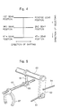
- the shift-assisting device 8 for operating the above-mentioned shifting mechanism 6 in the same direction as the direction in which the speed-change lever 3 is shifted.
- the shift-assisting device 8 is equipped with an electric motor 81 (M1) which is a source of driving power capable of rotating forward and reversely.
- a reduction gear 82 is coupled to the electric motor 81 (M1), and an end of the operation lever 83 is fitted to an output shaft 821 of the reduction gear 82.
- the control lever 62 is coupled, via a coupling rod 84, to the other end of the operation lever 83.
- the shift-assisting device 8 actuates the operation lever 83 in a direction indicated by an arrow 83a, and turns the control lever 62 in a direction indicated by an arrow 62a via the coupling rod 84 to assist the shifting operation.
- the shift-assisting device 8 actuates the operation lever 83 in a direction indicated by an arrow 83b and turns the control lever 62 in a direction indicated by an arrow 62b via the coupling rod 84 to assist the shifting operation.
- the shift-assisting device 8 in the illustrated embodiment has a shift stroke sensor 85 (SS) for detecting the shift stroke positions of the shifting mechanism.
- the shift stroke sensor 85 is coupled to the control lever 62 via a rod 86 and a lever 87, and comprises a potentiometer that detects the shift stroke positions depending upon the angle of operation of the control lever 62, and sends the detected signal to a controller 10.
- the controller 10 is constituted by a microcomputer which comprises a central processing unit (CPU) 101 for executing the operation according to a control program, a read-only memory (ROM) 102 for storing the control program and a map for controlling the speed of connecting the clutch, that will be described later, a random access memory (RAM) 103 for storing the results of operation, a timer (T) 104, an input interface 105 and an output interface 106.
- the input interface 105 of the thus constituted controller 10 receives signals detected by the first switch 41 (SW1) and the second switch 42 (SW2) constituting the shift knob switch 4 and a signal detected by the shift stroke sensor 85 (SS).
- the input interface 105 further receives a signal detected by a clutch pedal switch 91 (SW3) which detects the state of operation of a clutch pedal 9 for operating a clutch disposed between the engine that is not shown and the transmission 2.
- the clutch pedal switch 91 (SW3) is turned off in a state where the clutch pedal 9 is released, i.e., where the clutch pedal 9 is not depressed (clutch is connected), and produces a signal ON when the clutch pedal 9 is depressed to disconnect the clutch.
- the input interface 105 receives a signal detected by a clutch stroke sensor that detects the amount of engagement of the clutch instead of the clutch pedal 9.
- the output interface 106 outputs control signals to the electric motor 81 (M1) and the like.
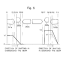
- Fig. 6 illustrates a positional relationship among the spline 252b of the clutch sleeve 252, the teeth 255a of the synchronizer ring 255 for the fifth speed gear 241 and dog teeth 241a, the teeth 256a of the synchronizer ring 256 for the fourth speed gear 242 and dog teeth 242a, in their neutral state.
- a shift stroke position of the clutch sleeve 252 in its neutral state is designated at P6.
- P5 denotes a shift stroke position of the clutch sleeve 252 that is moved from the neutral state toward the fifth speed gear 241 side (toward the left in Fig.
- P4 denotes a shift stroke position of the clutch sleeve 252 that arrives at a rear end of the teeth 255a of the synchronizer ring 255
- P3 denotes a shift stroke position of the clutch sleeve 252 that arrives at the front end of the chamfer of the dog teeth 241a for the fifth speed gear 241
- P2 denotes a shift stroke position of the clutch sleeve 252 that arrives at the rear end of the chamfer of the dog teeth 241a
- P1 denotes a shift stroke position of the clutch sleeve 252 that arrives at the rear end of the dog teeth 241a.
- P7 denotes a shift stroke position of the clutch sleeve 252 that is moved from the neutral state toward the fourth speed gear 242 side (toward the right in Fig. 6) and arrives at the front end of the chamfer of the teeth 256a of the synchronizer ring 256 for the fourth speed gear 242
- P8 denotes a shift stroke position of the clutch sleeve 252 that arrives at the rear end of the teeth 256a of the synchronizer ring 256
- P9 denotes a shift stroke position of the clutch sleeve 252 that arrives at the front end of the chamfer of the dog teeth 242a for the fourth speed gear 242
- P10 denotes a shift stroke position of the clutch sleeve 252 that arrives at the rear end of the chamfer of the dog teeth 242a
- P11 denotes a shift stroke position of the clutch sleeve 252 that arrives at the rear end of the dog teeth 242a.
- the shift stroke positions are detected by the shift stroke sensor 85 (SS).
- the shift stroke sensor 85 (SS) is so constituted as to produce a voltage signal of the smallest value when the shift stroke position is P1, to produce the output voltage that gradually increases as the shift stroke position goes to the P11 side and to produce a voltage signal of the greatest value when the shift stroke position is P11.
- the greatest operation force acts on the speed-change lever 3 in the synchronizing range of from the shift stroke positions P7 or P5, i.e., from the positions at which the synchronizing action starts up to the shift stroke position P8 or P4 at which the synchronizing action ends.
- the electric motor 81 (M1) may be driven in at least the synchronizing range to assist the shifting operation.
- a relatively large force acts on the speed-change lever 3 in the engaging range of from the shift stroke position P9 or P3 to the shift stroke position P10 or P2, i.e., in a range where the chamfer of the spline 252b of the clutch sleeve 252 engages with the chamfer of the dog teeth 242a or 241a.
- the shifting operation may be assisted by driving the electric motor 81 (M1) during the shift stroke of from the gear-engaged state until the rear end of the chamfer of the dog teeth is passed (i.e., in the range at which the dog teeth are in mesh with the clutch sleeve 52).
- the assisting force of during the gear-disengaging operation may be smaller than the assisting force of during the gear-engaging operation.
- the assisting force is controlled by controlling the voltage or the current applied to the electric motor 81 (M1).
- the rotation of the electric motor 81 (M1) is, for example, the forward rotation when the clutch sleeve 252 is operated toward the left in Fig. 6 (when the first switch 41 (SW1) of the shift knob switch 4 is turned on) and is, for example, the reverse rotation when the clutch sleeve 252 is operated toward the right in Fig. 6 (when the second switch 42 (SW2) of the shift knob switch 4 is turned on).
- the electric motor 81 (M1) is reversely driven with a voltage V1 during from P1 to P2, i.e., until the spline 252b of the clutch sleeve 252 passes the rear end of the chamfer of the dog teeth 241a (during a period in which the dog teeth are in mesh with the clutch sleeve 252) as shown in Fig. 6. Then, the voltage is gradually lowered during from P2 to P5 to stop the driving of the electric motor 81 (M1).
- the electric motor 81 (M1) is reversely driven with a voltage V2 that is higher than the above voltage V1.
- the reverse rotation is maintained with the voltage V2 for a period until the spline 252b of the clutch sleeve 252 passes P10 that corresponds to the rear end of the chamfer of the dog teeth 242a.
- the voltage applied to the electric motor 81 (M1) is gradually lowered to halt the driving of the electric motor 81 (M1) at the shift stroke position P11.
- the voltage applied to the electric motor 81 (M1) may be lowered from V2 to V1 as indicated by a broken line after the synchronizing period of P8 has elapsed and the electric motor 81 (M1) may be driven with a voltage V1 until reaching P10.
- the assisting force is controlled according to the shift stroke positions. Therefore, no time lag occurs in driving the electric motor, and the force for operating the speed-change lever can be leveled over the whole stroke in the shifting operation.
- the controller 10 checks whether the clutch pedal switch 91 (SW3) has been turned on, i.e., whether the clutch pedal 9 has been depressed to disconnect the clutch (step S1).
- the controller 10 judges whether the driver is not willing to change the speed since the clutch has not been disconnected, and the routine proceeds to step S2 to end the operation by bringing a halt to driving the electric motor 81 (M1).
- step S1 When the clutch pedal switch 91 (SW3) has been turned on at step S1, the controller 10 judges that the clutch has been disconnected and the driver is willing to change the speed, and the routine proceeds to step S3 where it is checked whether the first switch 41 (SW1) of the shift knob switch 4 is turned on, i.e., whether the operation has started to change the speed toward the first gear position, third gear position or fifth gear position.
- step S4 the controller 10 proceeds to step S4 to set the electric motor 81 (Ml) to turn forward and, then, proceeds to step S5 where it is checked whether the shift stroke position P detected by the shift stroke sensor 85 (SS) is smaller than P2, i.e., whether the clutch sleeve 252 is rather on the gear-engaging side than the rear end of the chamfer of the dog teeth 241a.
- step S5 the controller 10 judges that the clutch sleeve 252 is rather on the gear-engaging side than the rear end of the chamber of the dog teeth 241a and there is no need of assisting the shift.
- the routine then proceeds to step S6 where the voltage applied to the electric motor 81 (M1) is gradually decreased, and the voltage is nullified (0) after the shift stroke position P has reached P1.
- step S5 the controller 10 proceeds to step S7 and checks whether the shift stroke position P is larger than P2 but is smaller than P5, i.e., whether the clutch sleeve 252 is in a range of from a position of starting the synchronization up to a position where the dog teeth engage with the chamfer.
- the controller 10 judges that the clutch sleeve 252 is in the range of from the position of starting the synchronization to the position where the dog teeth are engaged with the chamfer, and that the shifting must be assisted during the gear-engaging operation.
- the routine therefore proceeds to step S8 where the electric motor 81 (M1) is driven with the voltage V2.
- step S9 checks whether the shift stroke position P is larger than P5 but is smaller than P7, i.e., whether the clutch sleeve 252 is positioned between the two synchronizer rings 255 and 256.
- the controller 10 judges that the clutch sleeve 252 is positioned between the two synchronizer rings 255 and 256 and that there is no need to assist the shifting operation.
- the routine proceeds to step S10 where the electric motor 81 (M1) is brought into a halt to driving.
- step S11 checks whether the shift stroke position P is larger than P7 but is smaller than P10, i.e., whether the clutch sleeve 252 is out of mesh with the dog teeth 242a and the gear-disengaging operation is completed.
- the controller 10 judges that the clutch sleeve 252 is out of mesh with the dog teeth 242a and the gear-disengaging operation has been completed.
- the routine proceeds to step S12 where the voltage applied to the electric motor 81 (M1) is gradually decreased, and the voltage is nullified (0) after the shift stroke position P has reached P7.
- the controller 10 judges that the clutch sleeve 252 is in mesh with the dog teeth 242a and that the shifting operation must be assisted during the gear-disengaging operation.
- the electric motor 81 (M1) therefore, is driven with the voltage V1.
- step S14 checks whether the second switch 42 (SW2) is turned on , i.e., whether the operation has started to change the speed toward the second gear position, fourth gear position or reverse gear position.
- the controller 10 judges that the driver is not willing to change the speed, and the routine proceeds to step S2 to end the operation by bringing the electric motor 81 (M1) into a halt.
- step S15 the controller 10 proceeds to step S15 to set the electric motor 81 (M1) to rotate in the reverse direction, and further proceeds to step S16 and checks whether the shift stroke position P detected by the shift stroke sensor 85 (SS) is larger than P10, i.e., whether the clutch sleeve 252 is rather on the gear-engaging side than the rear end of the chamfer of the dog teeth 242a.
- step S16 the controller 10 judges that the clutch sleeve 252 is rather on the gear-engaging side than the rear end of the chamfer of the dog teeth 242a and that there is no need to assist the shifting.
- the routine then proceeds to step S6 where the voltage applied to the electric motor 81(M1) is gradually decreased, and the voltage is nullified (0) after the shift stroke position P has reached P11.
- step S16 the controller 10 proceeds to step S17 and checks whether the shift stroke position P is larger than P7 but is smaller than P10, i.e., whether the clutch sleeve 252 is in a range of from a position for starting the synchronization to a position where the dog teeth engage with the chamfer.
- the controller 10 judges that the clutch sleeve 252 is in the range of from the position for starting the synchronization to the position where the dog teeth engage with the chamfer and that the shifting must be assisted during the gear-engaging operation.
- the routine proceeds to step S8 where the electric motor 81 (M1) is driven with the voltage V2.
- step S17 the controller 10 proceeds to step S18 and checks whether the shift stroke position P is larger than P5 but is smaller than P7, i.e., whether the clutch sleeve 252 is positioned between the two synchronizer rings 255 and 256.
- the controller 10 judges that the clutch sleeve 252 is positioned between the two synchronizer rings 255 and 256 and that there is no need to assist the shifting operation.
- the routine proceeds to step S10 where the electric motor 81 (M1) is brought into a halt to driving.
- step S19 checks whether the shift stroke position P is larger than P2 but is smaller than P5, i.e., whether the clutch sleeve 252 is out of mesh with the dog teeth 241a and the gear-disengaging operation is completed.
- the controller 10 judges that the clutch sleeve 252 is out of mesh with the dog teeth 241a and the gear-disengaging operation is completed.
- the routine proceeds to step S12 where the voltage applied to the electric motor 81 (M1) is gradually decreased, and the voltage is nullified (0) after the shift stroke position P has reached P5.
- the controller 10 judges that the clutch sleeve 252 is in mesh with the dog teeth 241a and that the shifting must be assisted during the gear-disengaging operation. Therefore, the electric motor 81 (M1) is driven with the voltage V1.
- the shift-assisting device for a transmission according to the present invention is constituted as described above, and exhibits actions and effects as described below.
- the shift-assisting device for a transmission comprises an electric motor for operating a shifting mechanism in the same direction as the direction in which a speed-change lever is shifted, said shifting mechanism being coupled to said speed-change lever to actuate a synchronizing mechanism of the transmission
- said shift-assisting device for a transmission comprises a shift stroke sensor for detecting a shift stroke position of said shifting mechanism, and a control means for outputting a control signal corresponding to the shift stroke position to said electric motor based on a signal detected by said shift stroke sensor. Therefore, since the assisting force is controlled according to the shift stroke position, without producing a time lag at the time of driving the electric motor, the force for operating the speed-change lever can be leveled over the whole stroke of the shifting operation.
Landscapes
- Engineering & Computer Science (AREA)
- General Engineering & Computer Science (AREA)
- Mechanical Engineering (AREA)
- Gear-Shifting Mechanisms (AREA)
- Control Of Transmission Device (AREA)
Applications Claiming Priority (2)
| Application Number | Priority Date | Filing Date | Title |
|---|---|---|---|
| JP2000046173 | 2000-02-23 | ||
| JP2000046173A JP2001235028A (ja) | 2000-02-23 | 2000-02-23 | 変速機のシフトアシスト装置 |
Publications (2)
| Publication Number | Publication Date |
|---|---|
| EP1128096A2 true EP1128096A2 (fr) | 2001-08-29 |
| EP1128096A3 EP1128096A3 (fr) | 2003-05-28 |
Family
ID=18568643
Family Applications (1)
| Application Number | Title | Priority Date | Filing Date |
|---|---|---|---|
| EP00127248A Withdrawn EP1128096A3 (fr) | 2000-02-23 | 2000-12-15 | Système d'assistance au changement de rapports |
Country Status (4)
| Country | Link |
|---|---|
| US (1) | US6637281B2 (fr) |
| EP (1) | EP1128096A3 (fr) |
| JP (1) | JP2001235028A (fr) |
| CN (1) | CN1314267A (fr) |
Cited By (4)
| Publication number | Priority date | Publication date | Assignee | Title |
|---|---|---|---|---|
| DE102006024487A1 (de) * | 2006-05-26 | 2007-11-29 | Schaeffler Kg | Schaltvorrichtung für ein Getriebe |
| EP1818569A4 (fr) * | 2004-10-13 | 2010-03-31 | Calsonic Kansei Corp | Mecanisme de selection de regime de fonctionnement d' une transmission automatique, module de transmission automatique dote du mecanisme de selection de regime de fonctionnement, et vehicule |
| EP2292950A1 (fr) | 2009-09-04 | 2011-03-09 | Renault S.A.S. | Dispositif d'assistance actif au passage des vitesses |
| CN103527765A (zh) * | 2013-10-31 | 2014-01-22 | 济南宏昌车辆有限公司 | 微型电动车高低速变档器 |
Families Citing this family (15)
| Publication number | Priority date | Publication date | Assignee | Title |
|---|---|---|---|---|
| JP4502103B2 (ja) * | 2002-03-27 | 2010-07-14 | スズキ株式会社 | 自動変速機 |
| US6904823B2 (en) * | 2002-04-03 | 2005-06-14 | Immersion Corporation | Haptic shifting devices |
| AU2003285886A1 (en) | 2002-10-15 | 2004-05-04 | Immersion Corporation | Products and processes for providing force sensations in a user interface |
| JP4187574B2 (ja) * | 2003-04-09 | 2008-11-26 | 株式会社デンソー | シフト制御システムおよびシフト制御方法 |
| US7194927B2 (en) * | 2003-09-17 | 2007-03-27 | Calsonic Kansei Corporation | Operating position select device for automatic transmission |
| JP2005221061A (ja) * | 2004-02-09 | 2005-08-18 | Calsonic Kansei Corp | 自動変速機のセレクトアシスト装置 |
| US7313980B2 (en) * | 2004-10-15 | 2008-01-01 | Calsonic Kansei Corporation | Operating position select device for automatic transmission |
| US7464621B2 (en) * | 2004-11-09 | 2008-12-16 | Steeda Autosports, Inc. | Longitudinally displaced shifter |
| KR100736954B1 (ko) * | 2005-10-25 | 2007-07-09 | 현대자동차주식회사 | 자동변속기 |
| JP4999395B2 (ja) * | 2006-07-31 | 2012-08-15 | 株式会社デンソー | レンジ切換機構の制御装置 |
| DE102009028340A1 (de) * | 2009-08-07 | 2011-02-10 | Zf Friedrichshafen Ag | Einrichtung zur Notentriegelung einer Parksperre eines Automatgetriebes eines Kraftfahrzeugs |
| GB2476985A (en) * | 2010-01-19 | 2011-07-20 | Gm Global Tech Operations Inc | Synchronization key having low wear |
| CN112984096B (zh) * | 2021-03-25 | 2022-04-22 | 安徽江淮汽车集团股份有限公司 | 一种换挡装置 |
| CN118030834A (zh) * | 2024-01-26 | 2024-05-14 | 东风汽车集团股份有限公司 | 换挡方法及装置、汽车、存储介质、计算机程序产品 |
| CN118775537A (zh) * | 2024-07-24 | 2024-10-15 | 江苏奥联车辆制造有限公司 | 非公路用旅游观光车辆自动换挡变速箱 |
Citations (3)
| Publication number | Priority date | Publication date | Assignee | Title |
|---|---|---|---|---|
| JPS5697133U (fr) | 1979-12-24 | 1981-08-01 | ||
| JPH0587237A (ja) | 1991-09-27 | 1993-04-06 | Fuji Univance:Kk | 操作力軽減装置 |
| JP2987121B2 (ja) | 1997-04-18 | 1999-12-06 | 京浜精密工業株式会社 | パワーシフタの制御装置 |
Family Cites Families (15)
| Publication number | Priority date | Publication date | Assignee | Title |
|---|---|---|---|---|
| US1313362A (en) * | 1919-08-19 | Henry j | ||
| US3049934A (en) * | 1961-01-27 | 1962-08-21 | John L Butler | Electrically assisted manual gear shift means |
| JPS5940047A (ja) * | 1982-08-31 | 1984-03-05 | Fuji Heavy Ind Ltd | オ−トクラツチ車の変速操作機構 |
| US4745822A (en) * | 1985-04-19 | 1988-05-24 | Rockwell International Corporation | Two speed axle |
| IT1188103B (it) * | 1986-04-23 | 1987-12-30 | Fiat Auto Spa | Dispositivo di comando motorizzato per cambi di velocita di autoveicoli |
| JPH0625593B2 (ja) * | 1987-09-29 | 1994-04-06 | いすゞ自動車株式会社 | 変速機制御装置 |
| AU619229B2 (en) * | 1988-12-16 | 1992-01-23 | Isuzu Motors Limited | Transmission control apparatus |
| FR2652547B1 (fr) * | 1989-09-29 | 1995-06-02 | Valeo | Timonerie de transmission de forces pour vehicules automobiles. |
| IT1251752B (it) * | 1991-10-31 | 1995-05-23 | Fiat Auto Spa | Dispositivo elettronico per la selezione delle marce in un cambio automatico per autoveicoli |
| DE4228797A1 (de) * | 1992-08-29 | 1994-03-03 | Porsche Ag | Schaltvorrichtung eines Kraftfahrzeuggetriebes |
| US5460060A (en) * | 1994-07-27 | 1995-10-24 | Eaton Corporation | Transmission shifting mechanism with spring loaded ball screw |
| FR2745098B1 (fr) * | 1996-02-19 | 1998-06-12 | Adwest Oci Sa | Dispositif d'asservissement d'un levier de commande d'une boite de vitesses pour vehicule automobile |
| DE19900820B4 (de) * | 1998-01-16 | 2013-03-14 | Schaeffler Technologies AG & Co. KG | Servounterstützungsvorrichtung für ein Getriebe |
| US6016717A (en) * | 1998-05-18 | 2000-01-25 | Teleflex Incorporated | Helical cable actuator for shift by wire system |
| JP3313327B2 (ja) * | 1998-07-30 | 2002-08-12 | アイシン・エーアイ株式会社 | シンクロメッシュ式トランスミッションのシフト制御装置 |
-
2000
- 2000-02-23 JP JP2000046173A patent/JP2001235028A/ja not_active Withdrawn
- 2000-12-15 EP EP00127248A patent/EP1128096A3/fr not_active Withdrawn
- 2000-12-19 US US09/739,232 patent/US6637281B2/en not_active Expired - Fee Related
-
2001
- 2001-02-23 CN CN01104322.9A patent/CN1314267A/zh active Pending
Patent Citations (3)
| Publication number | Priority date | Publication date | Assignee | Title |
|---|---|---|---|---|
| JPS5697133U (fr) | 1979-12-24 | 1981-08-01 | ||
| JPH0587237A (ja) | 1991-09-27 | 1993-04-06 | Fuji Univance:Kk | 操作力軽減装置 |
| JP2987121B2 (ja) | 1997-04-18 | 1999-12-06 | 京浜精密工業株式会社 | パワーシフタの制御装置 |
Cited By (5)
| Publication number | Priority date | Publication date | Assignee | Title |
|---|---|---|---|---|
| EP1818569A4 (fr) * | 2004-10-13 | 2010-03-31 | Calsonic Kansei Corp | Mecanisme de selection de regime de fonctionnement d' une transmission automatique, module de transmission automatique dote du mecanisme de selection de regime de fonctionnement, et vehicule |
| DE102006024487A1 (de) * | 2006-05-26 | 2007-11-29 | Schaeffler Kg | Schaltvorrichtung für ein Getriebe |
| EP2292950A1 (fr) | 2009-09-04 | 2011-03-09 | Renault S.A.S. | Dispositif d'assistance actif au passage des vitesses |
| FR2949836A1 (fr) * | 2009-09-04 | 2011-03-11 | Renault Sa | Dispositif d'assistance actif au passage des vitesses |
| CN103527765A (zh) * | 2013-10-31 | 2014-01-22 | 济南宏昌车辆有限公司 | 微型电动车高低速变档器 |
Also Published As
| Publication number | Publication date |
|---|---|
| CN1314267A (zh) | 2001-09-26 |
| US6637281B2 (en) | 2003-10-28 |
| EP1128096A3 (fr) | 2003-05-28 |
| US20010015109A1 (en) | 2001-08-23 |
| JP2001235028A (ja) | 2001-08-31 |
Similar Documents
| Publication | Publication Date | Title |
|---|---|---|
| EP1128096A2 (fr) | Système d'assistance au changement de rapports | |
| US6536297B2 (en) | Shift-assisting device for a transmission | |
| JP3590939B2 (ja) | 駆動系統トルクの検出に基づく変速機の制御装置およびその方法 | |
| US5984828A (en) | Control methods for a shift by wire vehicle transmission | |
| US6658950B2 (en) | Shift control device for a transmission | |
| JPH11325229A (ja) | レンジシフト操作制御装置及びその制御方法 | |
| EP1156237B1 (fr) | Système d'assistance au changement de rapports de transmission | |
| JPH11336885A (ja) | 車両変速システムにおけるレンジ部シフトの制御方法及びその制御装置 | |
| JPH07233870A (ja) | レンジ形複式変速機のシフト制御装置及びその方法 | |
| JP4622053B2 (ja) | 変速機のシフトアシスト装置 | |
| EP1160489B1 (fr) | Comande de passage de vitesses assistée | |
| JPH07301328A (ja) | 後退連結のインターロック制御方法およびその装置 | |
| JP2006153173A (ja) | 自動変速制御装置 | |
| JP3722689B2 (ja) | 同期噛合式自動変速機の制御装置 | |
| JPH11336886A (ja) | 車両変速システムの制御方法及びその制御装置 | |
| EP1925519A1 (fr) | Système de transmission manuelle automatique pour véhicule | |
| JPH0512507Y2 (fr) | ||
| JP4314734B2 (ja) | 変速機のシフト制御装置 | |
| JP2002071015A (ja) | 変速機のシフトアシスト装置 | |
| JP2001235030A (ja) | 変速機のシフトアシスト装置 | |
| JP2001235029A (ja) | 変速機のシフトアシスト装置 | |
| JP2001330148A (ja) | 変速機のシフトアシスト装置 | |
| JP2001280488A (ja) | 変速機のシフトアシスト装置 | |
| JP2001304405A (ja) | 変速機のシフトアシスト装置 | |
| JP2002013633A (ja) | 変速機のシフトアシスト装置 |
Legal Events
| Date | Code | Title | Description |
|---|---|---|---|
| PUAI | Public reference made under article 153(3) epc to a published international application that has entered the european phase |
Free format text: ORIGINAL CODE: 0009012 |
|
| AK | Designated contracting states |
Kind code of ref document: A2 Designated state(s): AT BE CH CY DE DK ES FI FR GB GR IE IT LI LU MC NL PT SE TR |
|
| AX | Request for extension of the european patent |
Free format text: AL;LT;LV;MK;RO;SI |
|
| PUAL | Search report despatched |
Free format text: ORIGINAL CODE: 0009013 |
|
| AK | Designated contracting states |
Designated state(s): AT BE CH CY DE DK ES FI FR GB GR IE IT LI LU MC NL PT SE TR |
|
| AX | Request for extension of the european patent |
Extension state: AL LT LV MK RO SI |
|
| RIC1 | Information provided on ipc code assigned before grant |
Ipc: 7F 16H 61/32 B Ipc: 7F 16H 61/28 A |
|
| 17P | Request for examination filed |
Effective date: 20031117 |
|
| AKX | Designation fees paid |
Designated state(s): DE FR GB |
|
| 17Q | First examination report despatched |
Effective date: 20040202 |
|
| STAA | Information on the status of an ep patent application or granted ep patent |
Free format text: STATUS: THE APPLICATION IS DEEMED TO BE WITHDRAWN |
|
| 18D | Application deemed to be withdrawn |
Effective date: 20040615 |