EP1128097B1 - Dispositif pour transmettre des mouvements de selection et/ou de changement de vitesse - Google Patents
Dispositif pour transmettre des mouvements de selection et/ou de changement de vitesse Download PDFInfo
- Publication number
- EP1128097B1 EP1128097B1 EP20010101781 EP01101781A EP1128097B1 EP 1128097 B1 EP1128097 B1 EP 1128097B1 EP 20010101781 EP20010101781 EP 20010101781 EP 01101781 A EP01101781 A EP 01101781A EP 1128097 B1 EP1128097 B1 EP 1128097B1
- Authority
- EP
- European Patent Office
- Prior art keywords
- carrier body
- support body
- actuating member
- cage
- shift
- Prior art date
- Legal status (The legal status is an assumption and is not a legal conclusion. Google has not performed a legal analysis and makes no representation as to the accuracy of the status listed.)
- Expired - Lifetime
Links
- 230000033001 locomotion Effects 0.000 title claims description 15
- 238000005096 rolling process Methods 0.000 claims description 48
- 230000005540 biological transmission Effects 0.000 claims description 9
- 229910052751 metal Inorganic materials 0.000 claims description 7
- 239000002184 metal Substances 0.000 claims description 7
- 238000006073 displacement reaction Methods 0.000 claims 1
- 238000013016 damping Methods 0.000 description 6
- 238000004519 manufacturing process Methods 0.000 description 4
- 239000000463 material Substances 0.000 description 3
- 238000000034 method Methods 0.000 description 3
- 229910000831 Steel Inorganic materials 0.000 description 2
- 238000005520 cutting process Methods 0.000 description 2
- 238000000465 moulding Methods 0.000 description 2
- 239000010959 steel Substances 0.000 description 2
- 238000003860 storage Methods 0.000 description 2
- 229910001369 Brass Inorganic materials 0.000 description 1
- 229910001018 Cast iron Inorganic materials 0.000 description 1
- 229910052782 aluminium Inorganic materials 0.000 description 1
- XAGFODPZIPBFFR-UHFFFAOYSA-N aluminium Chemical compound [Al] XAGFODPZIPBFFR-UHFFFAOYSA-N 0.000 description 1
- 239000010951 brass Substances 0.000 description 1
- 230000000694 effects Effects 0.000 description 1
- 230000006698 induction Effects 0.000 description 1
- 238000003825 pressing Methods 0.000 description 1
- 230000035939 shock Effects 0.000 description 1
Images

Classifications
-
- F—MECHANICAL ENGINEERING; LIGHTING; HEATING; WEAPONS; BLASTING
- F16—ENGINEERING ELEMENTS AND UNITS; GENERAL MEASURES FOR PRODUCING AND MAINTAINING EFFECTIVE FUNCTIONING OF MACHINES OR INSTALLATIONS; THERMAL INSULATION IN GENERAL
- F16H—GEARING
- F16H63/00—Control outputs from the control unit to change-speed- or reversing-gearings for conveying rotary motion or to other devices than the final output mechanism
- F16H63/02—Final output mechanisms therefor; Actuating means for the final output mechanisms
- F16H63/30—Constructional features of the final output mechanisms
-
- F—MECHANICAL ENGINEERING; LIGHTING; HEATING; WEAPONS; BLASTING
- F16—ENGINEERING ELEMENTS AND UNITS; GENERAL MEASURES FOR PRODUCING AND MAINTAINING EFFECTIVE FUNCTIONING OF MACHINES OR INSTALLATIONS; THERMAL INSULATION IN GENERAL
- F16H—GEARING
- F16H63/00—Control outputs from the control unit to change-speed- or reversing-gearings for conveying rotary motion or to other devices than the final output mechanism
- F16H63/02—Final output mechanisms therefor; Actuating means for the final output mechanisms
- F16H63/30—Constructional features of the final output mechanisms
- F16H63/32—Gear shift yokes, e.g. shift forks
-
- F—MECHANICAL ENGINEERING; LIGHTING; HEATING; WEAPONS; BLASTING
- F16—ENGINEERING ELEMENTS AND UNITS; GENERAL MEASURES FOR PRODUCING AND MAINTAINING EFFECTIVE FUNCTIONING OF MACHINES OR INSTALLATIONS; THERMAL INSULATION IN GENERAL
- F16H—GEARING
- F16H63/00—Control outputs from the control unit to change-speed- or reversing-gearings for conveying rotary motion or to other devices than the final output mechanism
- F16H63/02—Final output mechanisms therefor; Actuating means for the final output mechanisms
- F16H63/30—Constructional features of the final output mechanisms
- F16H2063/3079—Shift rod assembly, e.g. supporting, assembly or manufacturing of shift rails or rods; Special details thereof
-
- F—MECHANICAL ENGINEERING; LIGHTING; HEATING; WEAPONS; BLASTING
- F16—ENGINEERING ELEMENTS AND UNITS; GENERAL MEASURES FOR PRODUCING AND MAINTAINING EFFECTIVE FUNCTIONING OF MACHINES OR INSTALLATIONS; THERMAL INSULATION IN GENERAL
- F16H—GEARING
- F16H63/00—Control outputs from the control unit to change-speed- or reversing-gearings for conveying rotary motion or to other devices than the final output mechanism
- F16H63/02—Final output mechanisms therefor; Actuating means for the final output mechanisms
- F16H63/30—Constructional features of the final output mechanisms
- F16H63/32—Gear shift yokes, e.g. shift forks
- F16H2063/321—Gear shift yokes, e.g. shift forks characterised by the interface between fork body and shift rod, e.g. fixing means, bushes, cams or pins
-
- F—MECHANICAL ENGINEERING; LIGHTING; HEATING; WEAPONS; BLASTING
- F16—ENGINEERING ELEMENTS AND UNITS; GENERAL MEASURES FOR PRODUCING AND MAINTAINING EFFECTIVE FUNCTIONING OF MACHINES OR INSTALLATIONS; THERMAL INSULATION IN GENERAL
- F16H—GEARING
- F16H63/00—Control outputs from the control unit to change-speed- or reversing-gearings for conveying rotary motion or to other devices than the final output mechanism
- F16H63/02—Final output mechanisms therefor; Actuating means for the final output mechanisms
- F16H63/30—Constructional features of the final output mechanisms
- F16H63/32—Gear shift yokes, e.g. shift forks
- F16H2063/327—Gear shift yokes, e.g. shift forks essentially made of sheet metal
Definitions
- the invention relates to a device for transmitting selector and / or switching movements with at least one actuating member, a support member carrying the actuator and at least one roller bearing supporting the support body and arranged in the support body.
- Shift forks and similar actuators are disposed in devices for transferring selector and / or shift motions in variable transmissions. For this they are usually longitudinally displaceable relative to a transmission housing and / or pivotally mounted or fixed to support elements such as bolts, shift shafts or shift rails.
- the support member is relatively movably mounted to the transmission housing in the transmission housing or other gear fixed components.
- To serve as a bearing for the support elements To rolling or sliding bearings for longitudinal movements and / or rotational movements or pivoting movements. If the actuators are mounted on the support elements relatively movable to the support elements, this is often also done with rolling or plain bearings for rotational movements and / or pivotal movements.
- the actuator is provided with a support body which, usually designed as a hub, has a bore.
- a support body which, usually designed as a hub, has a bore.
- one or more rolling or sliding bearings are added.
- actuators are mounted on the support members by means of one or more bearings. The bearings are pressed with an outer ring in the bore of the support body.
- Such a device is in the generic DE 43 28 399A described.
- the designated as switching sleeve supporting body is movably mounted on a designated as a shaft journal support member and carries an engagement member for a shift finger.
- the support body is provided with a shift finger.
- the support body is formed integrally with the engagement element and the shift finger and, for example, of cast iron.
- the pivotable and longitudinally movable mounting of the support body on the support member is secured by a rolling bearing.
- the rolling bearing is formed of a bearing ring and rolling elements.
- the rolling elements are guided with a cage in the bearing ring.
- the raceways of the rolling elements inside are formed by the surface of the shaft journal.
- the outer raceways of the rolling elements are formed on the inside of the bearing ring, which is pressed into the support body.
- DE 44 16 319A1 shows a rolling bearing for supporting a shift rail or shift shaft, which is formed from an outer bearing ring and rolling elements.
- the outer raceways of the rolling elements are formed on the bearing ring.
- the rolling bearing also has a flange for immovably mounting the rolling bearing on a housing.
- a device for transmitting dialing and / or switching movements can, for. B. guide forks and damping elements be. With the guide forks, an articulated connection to externally arranged shift fingers or other similar device acting members is made.
- the one or more damping elements dampen shocks between the relatively movable elements of the device, such. B. a shift fork and fixed to the housing of the gearbox stop.
- the stop can z. B. be formed by another shift fork or arranged directly on the housing fixed point.
- the advantages of the storage of support bodies on support elements by means of rolling bearings are known and are for example in the low-friction function of the bearings and the associated effects on the ease of use.
- a variant of a bearing of a shift fork on a shift rod is shown on page 7.
- the rolling bearing is formed by rolling elements, in this case balls, which are guided individually, in pairs or in larger numbers behind or next to each other in a cage.
- the rolling elements roll on an inner raceway.
- the inner race is formed by the cross-sectionally circular outer contour of the shift rod.
- the outer race is part of the outer ring of the rolling bearing.
- the outer ring is formed by a thin-walled and drawn sleeve.
- the interior and Outer raceways are usually made hardened.
- Applications are known in which the inner race is formed by a, for example drawn and mounted on the shift rod inner ring.
- the cross section of the shift rod or other support element is not round, but has a rectangular or any other deviating from the circular shape profile, as it is often found in punched sheet metal support elements.
- the rolling bearing and its elements and the raceways are then suitably adapted to this geometry. It is also conceivable to use a roller bearing, which, as shown on page 11 of the above-mentioned product overview, is designed to be torsionally stiff for the transmission of torques or as an anti-rotation device.
- a supporting body usually a shift fork, shift finger and possibly also other transmission elements, such as an engagement for a shift finger of a shift shaft from.
- the rolling bearing is pressed into a receptacle, for example a bore, of the supporting body.
- the support body and the / the actuators are often integrally formed of brass, aluminum or sheet metal. The contour is complicated to manufacture, the material and weight content of such a device is relatively high. The pressing of the rolling bearing in the support body is relatively expensive. When mounting in the gearbox, large tolerance fields must be taken into account.
- the invention is based on the object to provide a device that can be produced easily and inexpensively, in particular in a mass production, with a reduced proportion of material and weight.
- the support body has at least one arranged on at least one longitudinally facing end of the support body and at least in the longitudinal direction on the support body protruding plastic disc.
- the plastic disc is preferably used as a damping element. This damping element acts when the device impulsively impinges on a travel limit during longitudinal movements or during pivoting movements. Mechanical vibrations and thus noises are damped.
- the device comprises an actuator, a support member supporting the actuator and at least one supporting body and arranged in the support body rolling bearing, wherein the rolling bearing rolling elements for the longitudinally movable and / or pivotable mounting of the support body on a support member, at least one rolling element cage and has at least one trained on the support body career.
- the device is formed at least from a unit of actuator, support body and storage.
- the inner raceway is formed by a, for example drawn, and mounted on the support member inner ring or by the surface of the support member .
- the cross section of the support element such as a shift shaft or shift rod, is not round, but has a rectangular or any other deviating from the circular shape profile, as it is often found in punched sheet metal support elements.
- a roller bearing as on page 11 of the above INA product overview is designed for transmitting torques or as anti-rotation device.
- a shift fork is provided in one embodiment of the invention. These and other actuators are further preferably pressed onto the support body.
- an embodiment of the invention provides that the support body and the actuator are machined from sheet metal and the shift fork is permanently attached to the support body.
- the support body may be drawn from tape, formed by a flared tube, wound from tape, or made by similar methods. Non-cutting processes can be used to achieve economical production, in particular in mass production.
- the raceways for the rolling elements, balls or needles or cylindrical rollers, the rolling bearing are formed by the inner circumferential surface, for example a cylindrical support body or in the support body molded profiles such as longitudinal grooves, and formed during the molding process of the support body.
- As the material for the support body all suitable steel grades are used, in particular curable steels are provided.
- the raceways are induction hardened or the support body is completely hardened by case hardening or through hardening process.
- a further embodiment of the invention provides a device whose cage is accommodated, at least in the longitudinal direction, movable relative to the track in a longitudinally aligned receptacle.
- a receptacle may be formed by a bore or by a circular hole, but also have all other conceivable and suitable cross-sectional profiles.
- the receptacle in turn is arranged in the support body.
- Preferably is a thin-walled chipless shaped cylindrical trained support body provided.
- a plastic disc is arranged, which projects axially beyond the support body and thus acts on a stop as a damping means in axial impact of the support body.
- the plastic disc is preferably formed as a perforated disc.
- a perforated disc On one or both sides of the support body such a perforated disc is arranged frontally. The support member protrudes through the hole of the disc in the support body in or out. The axial stop is then formed for example by the part of the perforated disc, which at least partially obscures the annular gap between the support member and the receptacle.
- a means for the path limitation in the longitudinal direction is furthermore provided.
- This means is formed by a protruding from the support body radially inwardly into the receptacle projection.
- This projection is preferably formed from the sheet of the support body or worked out differently.
- the preferred embodiment provides an inwardly flared shelf.
- travel limits such as lugs on the cage, which engage in a corresponding longitudinal groove or molding on the support body. The length of the groove or the extent of the shape determine the axial path or the pivot angle of the cage and thus of the support element.
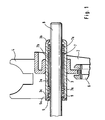
- FIG. 1 shows a device 1 for transmitting selection and / or switching movements with a shift fork 2 as an actuator, a support body 3, a guide fork 4 and a plastic disc 5 in partial section.
- the shift fork 2 sits with a press fit on the support body 3 and engages in a sliding sleeve 6 only partially shown.
- the support body 3, the shift fork 2 and the guide fork 4 are made of metal without cutting.
- the device 1 is mounted on a support element 8 by means of a roller bearing 7.
- the support element 8 is formed by a switching shaft only partially shown.
- the rolling bearing 7 consists of rolling elements 7a and a roller 7a leading cage 7b.
- the inner race of the rolling bearing 7 is formed by the outer circumferential surface of the support element 8.
- the outer race 3a is formed for the rolling elements 7a.
- the cage 7b is slidably disposed on the support member 8 with a limited travel.
- a means for the Wegbegrenzung of the cage 7b forms a board 3b of the support body 3.
- the plastic disc 5 forms an axial stop 9 for the cage 7b in this direction.
- the plastic disc 5 is provided with a centering 5a, which engages in the receptacle 3c of the support body 3 and the plastic disc 5 thus centered to the support body 3 and the support member 8.
- the plastic disc 5 is fixed by means of a press fit of the centering 5a in the receptacle 3c.
- FIG. 2 shows a non-inventive device 10 for transmitting dialing and / or switching movements with another shift fork 11 as an actuator, a guide fork 12 and a support body 13.
- the shift fork 11 and the guide fork 12 are fixed to the support body 13 inextricably by means of welds.
- the device 10 is longitudinally displaceable by means of a rolling bearing 14 and pivotally mounted on a support member 15.
- the shift fork 11 engages in a sliding sleeve 16 only partially shown.
- the rolling bearing 14 is formed by rolling elements 14a and 14a leading to the rolling elements 14a cage.
- the inner race of the rolling bearing 14 is the surface of the support element 15, on which the rolling bearing sits.
- the support body 13 has an outer raceway 13a for the rolling elements 14a of the rolling bearing 14.
- the support body 13 is formed from a widened and calibrated tube and has at its longitudinally facing ends in each case a means for limiting the travel of the cage 14b.
- the means for the Wegbegrenzung of the cage 14b is formed by a respective circumferential projecting from the support body 13 radially inwardly into the receptacle 13b pronounced projection 13c.
Landscapes
- Engineering & Computer Science (AREA)
- General Engineering & Computer Science (AREA)
- Mechanical Engineering (AREA)
- Bearings For Parts Moving Linearly (AREA)
- Gear-Shifting Mechanisms (AREA)
Claims (5)
- Dispositif (1, 10) pour la transmission de mouvements de sélection et/ou de mouvements de changement de vitesse, ledit dispositif comprenant, au moins, un membre d'actionnement, un corps de support (3, 13) pour supporter le membre d'actionnement et, au moins, un roulement (7, 14) agencé dans le corps de support (3, 13) pour supporter celui-ci, ledit roulement (7, 14), pour permettre un montage du corps de support (3, 13) en mouvement longitudinal et/ou en mouvement de pivotement sur un élément de support (8, 15), comprenant des corps roulants (7a, 14a), ledit roulement (7, 14) comprenant, en outre, au moins, une cage (7b, 14b) pour le guidage des corps roulants (7a, 14a) et, au moins, une piste (3a, 13a) de roulement configurée sur le corps de support (3, 13), caractérisé en ce que le corps de support (3) comprend, au moins, un disque (5) plastique qui est agencé à, au moins, l'une des extrémités du corps de support (3) orientée en direction longitudinale, et que ledit disque (5) s'étend, au moins, en direction longitudinale au-delà du corps de support (3).
- Dispositif selon la revendication 1, caractérisé en ce que le membre d'actionnement est constitué par une fourchette (2, 11) de changement de vitesse.
- Dispositif selon la revendication 1, caractérisé en ce que le corps de support (13) et le membre d'actionnement sont fabriqués sans enlèvement de copeaux à partir d'une tôle métallique, et que le membre d'actionnement est fixé au corps de support (13) par engagement à la presse.
- Dispositif selon la revendication 1, caractérisé en ce que le corps de support (3, 13) et le membre d'actionnement sont fabriqués sans enlèvement de copeaux à partir d'une tôle métallique, et que le membre d'actionnement est fixé de manière non détachable au corps de support (3, 13).
- Dispositif selon la revendication 1, caractérisé en ce que la cage (7b) est reçue en mouvement longitudinale par rapport à la piste (3a) de roulement dans une réception (3c) du corps de support (3) orientée en direction longitudinale, et que le disque (5) plastique est muni d'une butée axiale (9) pour la cage (7b).
Applications Claiming Priority (2)
| Application Number | Priority Date | Filing Date | Title |
|---|---|---|---|
| DE10008872 | 2000-02-25 | ||
| DE2000108872 DE10008872A1 (de) | 2000-02-25 | 2000-02-25 | Vorrichtung zum Übertragen von Wähl- und/oder Schaltbewegungen |
Publications (4)
| Publication Number | Publication Date |
|---|---|
| EP1128097A2 EP1128097A2 (fr) | 2001-08-29 |
| EP1128097A3 EP1128097A3 (fr) | 2005-01-19 |
| EP1128097B1 true EP1128097B1 (fr) | 2010-04-07 |
| EP1128097B8 EP1128097B8 (fr) | 2010-05-26 |
Family
ID=7632379
Family Applications (1)
| Application Number | Title | Priority Date | Filing Date |
|---|---|---|---|
| EP20010101781 Expired - Lifetime EP1128097B8 (fr) | 2000-02-25 | 2001-01-26 | Dispositif pour transmettre des mouvements de selection et/ou de changement de vitesse |
Country Status (3)
| Country | Link |
|---|---|
| EP (1) | EP1128097B8 (fr) |
| BR (1) | BR0100687B1 (fr) |
| DE (2) | DE10008872A1 (fr) |
Families Citing this family (10)
| Publication number | Priority date | Publication date | Assignee | Title |
|---|---|---|---|---|
| DE10360291A1 (de) * | 2003-12-20 | 2005-07-14 | Ina-Schaeffler Kg | Wankstabilisator |
| DE102006053732A1 (de) | 2006-11-15 | 2008-05-21 | Schaeffler Kg | Betätigungsvorrichtung für ein bewegliches Teil eines Zahnräderwechselgetriebes |
| DE602006011924D1 (de) | 2006-12-11 | 2010-03-11 | Fiat Ricerche | Getriebe für ein Kraftfahrzeug |
| ATE470811T1 (de) | 2007-12-18 | 2010-06-15 | Fiat Ricerche | Kraftfahrzeuggetriebe |
| DE102008061888A1 (de) * | 2008-12-11 | 2010-06-17 | Schaeffler Kg | Lageranordnung zur Lagerung einer Welle, Schaltdombaueinheit mit der Lageranordnung sowie Verfahren |
| US8627739B2 (en) * | 2009-09-15 | 2014-01-14 | GM Global Technology Operations LLC | Dual fork single shift rail assembly |
| DE102011105453A1 (de) * | 2011-06-22 | 2012-12-27 | GM Global Technology Operations LLC (n. d. Gesetzen des Staates Delaware) | Übertragungsglied für ein Fahrzeuggetriebe, insbesondere Schaltgabel |
| DE102013200889A1 (de) | 2013-01-21 | 2014-07-24 | Schaeffler Technologies Gmbh & Co. Kg | Vorrichtung zur Übertragung von Wähl- und/oder Schaltbewegungen in einem Zahnräderwechselgetriebe |
| DE102014220825B4 (de) | 2014-10-15 | 2016-09-29 | Schaeffler Technologies AG & Co. KG | Kugellagerkäfig |
| DE102022201401B4 (de) | 2022-02-10 | 2025-08-21 | Magna Pt B.V. & Co. Kg | Schaltvorrichtung und Verfahren zum Verschieben von Schaltgabeln auf einer Schaltstange |
Family Cites Families (5)
| Publication number | Priority date | Publication date | Assignee | Title |
|---|---|---|---|---|
| DE4116823A1 (de) * | 1991-05-23 | 1992-11-26 | Zahnradfabrik Friedrichshafen | Handschaltgetriebe fuer kraftfahrzeuge |
| DE4328399A1 (de) * | 1993-08-24 | 1995-03-02 | Schaeffler Waelzlager Kg | Schalteinrichtung für ein Zahnräderwechselgetriebe eines Kraftfahrzeuges |
| DE4416319A1 (de) * | 1994-05-09 | 1995-11-16 | Schaeffler Waelzlager Kg | Lagereinheit mit einer Zentrierung und einem Flansch |
| DE29501701U1 (de) * | 1995-02-03 | 1995-04-13 | Griesemer, Albert, 56457 Westerburg | Schwinggabel für Schaltgetriebe von Kraftfahrzeugen |
| FR2762659B1 (fr) * | 1997-04-25 | 1999-06-25 | Peugeot | Fourchette coulissante de boite de vitesses et agencement de cette fourchette sur un axe solidaire d'une fourchette en tole |
-
2000
- 2000-02-25 DE DE2000108872 patent/DE10008872A1/de not_active Withdrawn
-
2001
- 2001-01-26 EP EP20010101781 patent/EP1128097B8/fr not_active Expired - Lifetime
- 2001-01-26 DE DE50115418T patent/DE50115418D1/de not_active Expired - Lifetime
- 2001-02-21 BR BR0100687A patent/BR0100687B1/pt not_active IP Right Cessation
Also Published As
| Publication number | Publication date |
|---|---|
| EP1128097A2 (fr) | 2001-08-29 |
| BR0100687A (pt) | 2001-10-09 |
| BR0100687B1 (pt) | 2009-05-05 |
| EP1128097B8 (fr) | 2010-05-26 |
| DE50115418D1 (de) | 2010-05-20 |
| EP1128097A3 (fr) | 2005-01-19 |
| DE10008872A1 (de) | 2001-08-30 |
Similar Documents
| Publication | Publication Date | Title |
|---|---|---|
| EP2464895B1 (fr) | Procédé de production de l'écrou fileté d'une vis à billes | |
| WO2002064989A1 (fr) | Dispositif de guidage lineaire pour la transmission de couples | |
| DE19933875B4 (de) | Linearwälzlager zum Übertragen von Drehmomenten | |
| DE102012007329B4 (de) | Welle-Nabe-Verbindung | |
| EP1128097A2 (fr) | Dispositif pour transmettre des mouvements de selection et/ou de changement de vitesse | |
| DE19631214A1 (de) | Lenkspindel für ein Kraftfahrzeug | |
| DE102007045671A1 (de) | Wälzlagerung für axial gegeneinander verschiebbare Bauteile, insbesondere für Getriebe-Schaltelemente | |
| EP2132464B1 (fr) | Barillet de sélection | |
| EP1440260B1 (fr) | Mecanisme de manoeuvre et logement de palier dans une boite de vitesses | |
| WO2006089636A1 (fr) | Volant d'inertie a deux masses d'un vehicule automobile et palier a roulement pour un volant d'inertie a deux masses de ce type | |
| EP1711728B1 (fr) | Fourchette de boite de vitesses | |
| AT510576B1 (de) | Lagereinheit für eine schaltvorrichtung eines kraftfahrzeuggetriebes | |
| EP4111074B1 (fr) | Pendule à force centrifuge comportant une voie de roulement exposée axialement et dispositif de transmission de couple | |
| DE102005053989B4 (de) | Verfahren zur Herstellung eines Kupplungskörpers | |
| WO2015169525A1 (fr) | Dispositif d'actionnement d'un élément de commande à complémentarité de forme | |
| WO2014059981A1 (fr) | Dispositif de changement de vitesse d'une boîte de vitesses de véhicule à moteur | |
| EP2191154B1 (fr) | Palier à roulement pour des pièces pouvant être décalées axialement les unes par rapport aux autres, en particulier pour des éléments de changement de vitesse | |
| DE102008035960A1 (de) | Verstellbares Riemengetriebe | |
| DE102007008960B4 (de) | Betätigungseinrichtung | |
| WO2004018888A1 (fr) | Articulation coulissante | |
| WO2017036473A1 (fr) | Élément de roulement pour dispositif à pendules centrifuges | |
| DE102024201712A1 (de) | Anordnung mit einem ersten Bauteil und einem zweiten Bauteil | |
| DE102014220825B4 (de) | Kugellagerkäfig | |
| DE102021206348A1 (de) | Kreuzgelenk für eine Lenkwelle eines Kraftfahrzeugs, Lenkwelle für eine Kraftfahrzeuglenkung, Lenksystem für ein Kraftfahrzeug und Gelenkkreuz für ein Kreuzgelenk | |
| DE102008030151A1 (de) | Tripodegelenk für ein Kraftfahrzeug und Verfahren zu dessen Herstellung |
Legal Events
| Date | Code | Title | Description |
|---|---|---|---|
| PUAI | Public reference made under article 153(3) epc to a published international application that has entered the european phase |
Free format text: ORIGINAL CODE: 0009012 |
|
| 17P | Request for examination filed |
Effective date: 20010126 |
|
| AK | Designated contracting states |
Kind code of ref document: A2 Designated state(s): AT BE CH CY DE DK ES FI FR GB GR IE IT LI LU MC NL PT SE TR |
|
| AX | Request for extension of the european patent |
Free format text: AL;LT;LV;MK;RO;SI |
|
| RAP1 | Party data changed (applicant data changed or rights of an application transferred) |
Owner name: INA-SCHAEFFLER KG |
|
| PUAL | Search report despatched |
Free format text: ORIGINAL CODE: 0009013 |
|
| AK | Designated contracting states |
Kind code of ref document: A3 Designated state(s): AT BE CH CY DE DK ES FI FR GB GR IE IT LI LU MC NL PT SE TR |
|
| AX | Request for extension of the european patent |
Extension state: AL LT LV MK RO SI |
|
| RIC1 | Information provided on ipc code assigned before grant |
Ipc: 7F 16H 63/30 A |
|
| AKX | Designation fees paid |
Designated state(s): DE FR GB IT SE |
|
| RAP1 | Party data changed (applicant data changed or rights of an application transferred) |
Owner name: SCHAEFFLER KG |
|
| GRAP | Despatch of communication of intention to grant a patent |
Free format text: ORIGINAL CODE: EPIDOSNIGR1 |
|
| GRAS | Grant fee paid |
Free format text: ORIGINAL CODE: EPIDOSNIGR3 |
|
| GRAA | (expected) grant |
Free format text: ORIGINAL CODE: 0009210 |
|
| AK | Designated contracting states |
Kind code of ref document: B1 Designated state(s): DE FR GB IT SE |
|
| REG | Reference to a national code |
Ref country code: GB Ref legal event code: FG4D Free format text: NOT ENGLISH |
|
| RAP2 | Party data changed (patent owner data changed or rights of a patent transferred) |
Owner name: SCHAEFFLER TECHNOLOGIES GMBH & CO. KG |
|
| REF | Corresponds to: |
Ref document number: 50115418 Country of ref document: DE Date of ref document: 20100520 Kind code of ref document: P |
|
| PG25 | Lapsed in a contracting state [announced via postgrant information from national office to epo] |
Ref country code: SE Free format text: LAPSE BECAUSE OF FAILURE TO SUBMIT A TRANSLATION OF THE DESCRIPTION OR TO PAY THE FEE WITHIN THE PRESCRIBED TIME-LIMIT Effective date: 20100407 |
|
| PLBE | No opposition filed within time limit |
Free format text: ORIGINAL CODE: 0009261 |
|
| STAA | Information on the status of an ep patent application or granted ep patent |
Free format text: STATUS: NO OPPOSITION FILED WITHIN TIME LIMIT |
|
| 26N | No opposition filed |
Effective date: 20110110 |
|
| PG25 | Lapsed in a contracting state [announced via postgrant information from national office to epo] |
Ref country code: IT Free format text: LAPSE BECAUSE OF FAILURE TO SUBMIT A TRANSLATION OF THE DESCRIPTION OR TO PAY THE FEE WITHIN THE PRESCRIBED TIME-LIMIT Effective date: 20100407 |
|
| GBPC | Gb: european patent ceased through non-payment of renewal fee |
Effective date: 20110126 |
|
| REG | Reference to a national code |
Ref country code: FR Ref legal event code: ST Effective date: 20110930 |
|
| PG25 | Lapsed in a contracting state [announced via postgrant information from national office to epo] |
Ref country code: FR Free format text: LAPSE BECAUSE OF NON-PAYMENT OF DUE FEES Effective date: 20110131 |
|
| PG25 | Lapsed in a contracting state [announced via postgrant information from national office to epo] |
Ref country code: GB Free format text: LAPSE BECAUSE OF NON-PAYMENT OF DUE FEES Effective date: 20110126 |
|
| REG | Reference to a national code |
Ref country code: DE Ref legal event code: R081 Ref document number: 50115418 Country of ref document: DE Owner name: SCHAEFFLER TECHNOLOGIES AG & CO. KG, DE Free format text: FORMER OWNER: SCHAEFFLER TECHNOLOGIES GMBH & CO. KG, 91074 HERZOGENAURACH, DE Effective date: 20120828 Ref country code: DE Ref legal event code: R081 Ref document number: 50115418 Country of ref document: DE Owner name: SCHAEFFLER TECHNOLOGIES GMBH & CO. KG, DE Free format text: FORMER OWNER: SCHAEFFLER TECHNOLOGIES GMBH & CO. KG, 91074 HERZOGENAURACH, DE Effective date: 20120828 |
|
| REG | Reference to a national code |
Ref country code: DE Ref legal event code: R081 Ref document number: 50115418 Country of ref document: DE Owner name: SCHAEFFLER TECHNOLOGIES GMBH & CO. KG, DE Free format text: FORMER OWNER: SCHAEFFLER TECHNOLOGIES AG & CO. KG, 91074 HERZOGENAURACH, DE Effective date: 20140214 Ref country code: DE Ref legal event code: R081 Ref document number: 50115418 Country of ref document: DE Owner name: SCHAEFFLER TECHNOLOGIES AG & CO. KG, DE Free format text: FORMER OWNER: SCHAEFFLER TECHNOLOGIES AG & CO. KG, 91074 HERZOGENAURACH, DE Effective date: 20140214 |
|
| REG | Reference to a national code |
Ref country code: DE Ref legal event code: R081 Ref document number: 50115418 Country of ref document: DE Owner name: SCHAEFFLER TECHNOLOGIES AG & CO. KG, DE Free format text: FORMER OWNER: SCHAEFFLER TECHNOLOGIES GMBH & CO. KG, 91074 HERZOGENAURACH, DE Effective date: 20150210 |
|
| PGFP | Annual fee paid to national office [announced via postgrant information from national office to epo] |
Ref country code: DE Payment date: 20160331 Year of fee payment: 16 |
|
| REG | Reference to a national code |
Ref country code: DE Ref legal event code: R119 Ref document number: 50115418 Country of ref document: DE |
|
| PG25 | Lapsed in a contracting state [announced via postgrant information from national office to epo] |
Ref country code: DE Free format text: LAPSE BECAUSE OF NON-PAYMENT OF DUE FEES Effective date: 20170801 |
|
| P01 | Opt-out of the competence of the unified patent court (upc) registered |
Effective date: 20230522 |