EP1128115A2 - Rohrpressverbindung - Google Patents
Rohrpressverbindung Download PDFInfo
- Publication number
- EP1128115A2 EP1128115A2 EP01250031A EP01250031A EP1128115A2 EP 1128115 A2 EP1128115 A2 EP 1128115A2 EP 01250031 A EP01250031 A EP 01250031A EP 01250031 A EP01250031 A EP 01250031A EP 1128115 A2 EP1128115 A2 EP 1128115A2
- Authority
- EP
- European Patent Office
- Prior art keywords
- press
- section
- trough
- ring
- area
- Prior art date
- Legal status (The legal status is an assumption and is not a legal conclusion. Google has not performed a legal analysis and makes no representation as to the accuracy of the status listed.)
- Granted
Links
- 230000006835 compression Effects 0.000 title 1
- 238000007906 compression Methods 0.000 title 1
- 229910052751 metal Inorganic materials 0.000 claims abstract description 4
- 239000002184 metal Substances 0.000 claims abstract description 3
- 238000003825 pressing Methods 0.000 claims description 13
- 238000007789 sealing Methods 0.000 claims description 13
- 230000015572 biosynthetic process Effects 0.000 claims description 2
- 230000037431 insertion Effects 0.000 claims 2
- 238000003780 insertion Methods 0.000 claims 2
- 239000004033 plastic Substances 0.000 description 4
- 238000005516 engineering process Methods 0.000 description 3
- 239000000463 material Substances 0.000 description 3
- RYGMFSIKBFXOCR-UHFFFAOYSA-N Copper Chemical compound [Cu] RYGMFSIKBFXOCR-UHFFFAOYSA-N 0.000 description 2
- 239000012141 concentrate Substances 0.000 description 2
- 229910052802 copper Inorganic materials 0.000 description 2
- 239000010949 copper Substances 0.000 description 2
- 238000010438 heat treatment Methods 0.000 description 2
- 229910000851 Alloy steel Inorganic materials 0.000 description 1
- 229910000975 Carbon steel Inorganic materials 0.000 description 1
- 239000011324 bead Substances 0.000 description 1
- 229920005549 butyl rubber Polymers 0.000 description 1
- 239000010962 carbon steel Substances 0.000 description 1
- 238000002788 crimping Methods 0.000 description 1
- 230000005489 elastic deformation Effects 0.000 description 1
- 239000013013 elastic material Substances 0.000 description 1
- 229920001971 elastomer Polymers 0.000 description 1
- 238000009434 installation Methods 0.000 description 1
- 238000004519 manufacturing process Methods 0.000 description 1
- 238000000034 method Methods 0.000 description 1
- 239000000565 sealant Substances 0.000 description 1
- 238000005476 soldering Methods 0.000 description 1
- 230000007704 transition Effects 0.000 description 1
- 238000003466 welding Methods 0.000 description 1
Images


Classifications
-
- F—MECHANICAL ENGINEERING; LIGHTING; HEATING; WEAPONS; BLASTING
- F16—ENGINEERING ELEMENTS AND UNITS; GENERAL MEASURES FOR PRODUCING AND MAINTAINING EFFECTIVE FUNCTIONING OF MACHINES OR INSTALLATIONS; THERMAL INSULATION IN GENERAL
- F16L—PIPES; JOINTS OR FITTINGS FOR PIPES; SUPPORTS FOR PIPES, CABLES OR PROTECTIVE TUBING; MEANS FOR THERMAL INSULATION IN GENERAL
- F16L13/00—Non-disconnectable pipe joints, e.g. soldered, adhesive, or caulked joints
- F16L13/14—Non-disconnectable pipe joints, e.g. soldered, adhesive, or caulked joints made by plastically deforming the material of the pipe, e.g. by flanging, rolling
- F16L13/141—Non-disconnectable pipe joints, e.g. soldered, adhesive, or caulked joints made by plastically deforming the material of the pipe, e.g. by flanging, rolling by crimping or rolling from the outside
Definitions
- the invention relates to a pipe press connection, consisting of a Press fitting element made of metal and a metallic inserted therein Line pipe according to the preamble of claim 1.
- the press fitting system for house installation made of carbon steel or high-alloy steel and copper are known (see brochure mapress mannesmann pressfitting system, delivery program sanitary, heating, September 1998, as well mapress copper 03/1999).
- This system essentially consists of a plastic deformable metallic press fitting element, which depending on the training as a bow or T-piece or sleeve or transition piece at least one bead-like in cross-section trained, has a sealing ring receiving area and an in Connects longitudinally extending, cylindrically shaped area. At the end the extent of this cylindrical area is a radial inward extending bead-shaped depression pressed as a stop for the insertable, smooth-ended pipe.
- the bead-like end is plastic and the included sealing ring elastically deformed.
- the same Pressing process in the cylindrical area of the press fitting element in the immediate vicinity the bead-like end pressed a bead-shaped depression, which also inserted tube underneath captured.
- the elastically deformed sealing ring takes over the sealing function in this connection system, while the pressed Bead-shaped depression the longitudinal forces caused by the internal pressure as well takes up some of the moments.
- the sealing ring is made of a rubber elastic Material such as B. butyl rubber usually made in the form of a round sealing ring.
- connection system consisting of two tubes is known from US 4,850,621 known.
- the one pipe either points inwards or ring bulge extending outwards into which there is a separate sealing ring can be arranged.
- the same pipe has an area that is in with Seen a plurality of slots is provided circumferentially.
- this area encompassing the slit area becomes a trough-like Deepening of the inserted other tube pressed.
- the inserted tube has another ring bead, which acts as a stop for the pushed pipe serves or over which the pushed pipe with the Slot area extends.
- the disadvantage of this system is that the area of application of the connection system is limited by the material used for the sealing ring and the manufacture of a tube having a slotted area is complex.
- the object of the invention is to provide a pipe press connection, which under Retaining the proven pressing technology is universally applicable and with the especially higher temperatures and / or the transport of aggressive media. is manageable. Another task is for the proposed one Pipe press connection also the press jaws already available on the market to be able to use.
- dispensing with the arrangement of a separate Sealant the press fitting element at least one trough-shaped thin-walled section in which a form-fit clipable ring can be inserted, whose inner diameter is slightly smaller than that after the form fit Outside diameter of the bottom region of the trough-like section.
- This arrangement is in the contact area between the press fitting element and inserted pipe formed a metallic seal, without the arrangement of a rubber-elastic sealing ring.
- the application area of the proposed pipe press connection only through that for the press fitting element and the pipe used determines the material used.
- the trough-like trained section protruding outer contour of the ring so designed that it corresponds approximately to the recess of the press jaws on the market.
- the Bottom area of the trough-like section a circumferential elevation on. This elevation is preferably arranged symmetrically in the section.
- the end areas of the ring are the end areas of the ring as hook-shaped Closure trained.
- the pressing tongs have the ring in the Locking area each have a radially outwardly extending stop.
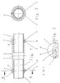
- Figure 1 is a longitudinal section of a first embodiment of the invention trained pipe press connection 1 shown. It consists of one Press fitting element 2 in the form of a cylindrical sleeve, each in both end regions has a trough-shaped, thin-walled section 3, 3 '. In this Section 3, 3 'is a positively clipable ring 4, 4' can be inserted. Training the The end region of the ring 4, 4 'is explained in FIGS. 7-10. To form a Pipe press connection 1 is in the press fitting element 2 of the smooth end region a conduit 5, 5 'inserted. By means of press jaws 16, 16 '(FIG.
- one here Crimping tool is in the contact area after closing the ring 4, 4 ' between the trough-shaped section 3, 3 'and the respective Line pipe 5.5 'formed a metallic seal.
- This is also called Seal level 6 denotes.
- the axial level representing strength level 7 generated.
- existing press jaws can also be used for this pipe press connection 1, corresponds to the outer projecting beyond the trough-like section 3.3 ' Contour 18 of the respective ring 4,4 'about the recess 19 of the already existing press jaws.
- the bottom area of the trough-shaped section 3, 3 ' has a circumferential survey 8.8 '.
- the inner diameter of the ring is 4,4 ' after the formation of the positive connection is slightly smaller than the outer diameter of the Elevation 8.8 'of the thin-walled section 3.3'.
- FIG. 4 shows a second embodiment in the same longitudinal section as FIG. 1, the same reference numerals have been chosen for the same parts. Is different only that the press fitting element 10 is thin-walled in both end regions trough-shaped section 12, 12 'is provided, the bottom region of which is flat is. The form-lockable ring 11, 11 'is suitable on its underside also just trained for this.
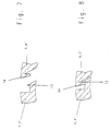
- FIGS. 7 and 8 show the respective end area in an enlarged view of the positively clipable ring 4, 4 'shown. Both end areas each have a hook 13, 14, one in the closed position shown in FIG Form fit. This is achieved in that the outer radial extension of the respective hook 13, 14 is on a different diameter.
- Figures 9 and 10 show another type of execution of the ring 15. So that Press jaws 16, 16 'of the pressing tongs, not shown here, can be attached more easily, the respective end region of the ring 15 faces radially outward extending web 17, 17 '.
Landscapes
- Engineering & Computer Science (AREA)
- General Engineering & Computer Science (AREA)
- Mechanical Engineering (AREA)
- Quick-Acting Or Multi-Walled Pipe Joints (AREA)
- Non-Disconnectible Joints And Screw-Threaded Joints (AREA)
- Mutual Connection Of Rods And Tubes (AREA)
- Mechanical Coupling Of Light Guides (AREA)
Abstract
Description
- Figur 1
- in einem Längsschnitt eine erste Ausführungsform einer erfindungsgemäß ausgebildeten Rohrpreßverbindung
- Figur 2
- einen Schnitt in Richtung A-A in Figur 1
- Figur 3
- im vergrößerten Maßstab das Detail X in Figur 1
- Figur 4
- wie Figur 1, aber eine zweite Ausführungsform
- Figur 5
- einen Schnitt in Richtung B-B in Figur 4
- Figur 6
- im vergrößerten Maßstab das Detail Y in Figur 4
- Figur 7
- den Endbereich des Ringes in geöffneter Stellung
- Figur 8
- wie Figur 7, aber in geschlossener Stellung
- Figur 9
- wie Figur 7, aber eine zweite Ausführungsform
- Figur 10
- wie Figur 8, aber eine zweite Ausführungsform
Claims (6)
- Rohrpreßverbindung, bestehend aus einem Preßfittingelement aus Metall, das mindestens einen dichtenden Bereich und einen daran anschließenden, der Einschubseite abgewandten, zylindrisch ausgebildeten Bereich aufweist und einem dünnwandigen metallischen Leitungsrohr, dessen glattendiger Endbereich in das Preßfittingelement eingeschoben und mittels eines das Preßfittingelement umfassenden, mindestens zwei Preßbacken aufweisenden Preßwerkzeuges nach dem Ansetzen und Schließen eine unlösbare, dichte Rohrpreßverbindung gebildet wird, wobei während des Verpressens die Preßbacken sowohl auf den dichtenden Bereich, als auch auf den der Einschubseite abgewandten zylindrisch ausgebildeten Abschnitt des Preßfittingelementes einwirken,
dadurch gekennzeichnet,
daß das Preßfittingelement (2,10) mindestens einen dünnwandigen, muldenartig ausgebildeten Abschnitt (3,3',12,12') aufweist, in dem ein formschlüssig clipsbarer offener Ring (4,4',11,11') einlegbar ist, dessen Innendurchmesser nach der Bildung des Formschlusses etwas geringer ist als der Außendurchmesser des Bodenbereiches des muldenartigen Abschnittes (3,3',12,2'), wobei der muldenartige Bereich mit dem darunter liegenden Mantelbereich des Leitungsrohres (5,5') eine metallische Abdichtung bildet. - Rohrpreßverbindung nach Anspruch 1,
dadurch gekennzeichnet,
daß die über den muldenartig ausgebildeten Abschnitt (3,3',12,12') überstehende äußere Kontur (18) des Ringes (4,4',11,11') etwa der Ausnehmung (19) der im Markt befindlichen Preßbacken (16,16') entspricht. - Rohrpreßverbindung nach Anspruch 1 und 2,
dadurch gekennzeichnet,
daß der Bodenbereich des muldenartig ausgebildeten Abschnittes (3,3)'eine umlaufende Erhebung (8) aufweist. - Rohrpreßverbindung nach Anspruch 3,
dadurch gekennzeichnet,
daß die Erhebung (8) symmetrisch im Abschnitt (3,3') angeordnet ist. - Rohrpreßverbindung nach einem der Ansprüche 1 bis 4,
dadurch gekennzeichnet,
daß die Endbereiche des einlegbaren Ringes (3,3',11,11') als hakenförmiger (13,14) Verschluß ausgebildet sind. - Rohrpreßverbindung nach einem der Ansprüche 1 bis 5,
dadurch gekennzeichnet,
daß der Ring (15) im Verschlußbereich mit je einem radial nach außen sich erstreckenden Anschlag (17,17') versehen ist.
Applications Claiming Priority (2)
| Application Number | Priority Date | Filing Date | Title |
|---|---|---|---|
| DE10009738A DE10009738C2 (de) | 2000-02-23 | 2000-02-23 | Rohrpressverbindung |
| DE10009738 | 2000-02-23 |
Publications (3)
| Publication Number | Publication Date |
|---|---|
| EP1128115A2 true EP1128115A2 (de) | 2001-08-29 |
| EP1128115A3 EP1128115A3 (de) | 2003-05-28 |
| EP1128115B1 EP1128115B1 (de) | 2005-08-31 |
Family
ID=7632951
Family Applications (1)
| Application Number | Title | Priority Date | Filing Date |
|---|---|---|---|
| EP01250031A Expired - Lifetime EP1128115B1 (de) | 2000-02-23 | 2001-01-30 | Rohrpressverbindung |
Country Status (3)
| Country | Link |
|---|---|
| EP (1) | EP1128115B1 (de) |
| AT (1) | ATE303545T1 (de) |
| DE (2) | DE10009738C2 (de) |
Cited By (3)
| Publication number | Priority date | Publication date | Assignee | Title |
|---|---|---|---|---|
| EP1491809A1 (de) * | 2003-06-25 | 2004-12-29 | Geberit Mapress GmbH | Rohrpressverbindung |
| US9188260B2 (en) | 2008-08-01 | 2015-11-17 | Nibco Inc. | Crimp evident seal |
| US12060954B2 (en) | 2019-03-26 | 2024-08-13 | Nibco Inc. | Piping component and sealing element for insertion therein |
Families Citing this family (1)
| Publication number | Priority date | Publication date | Assignee | Title |
|---|---|---|---|---|
| DE102020107498A1 (de) | 2020-03-18 | 2021-09-23 | Conex Universal Limited | Pressverbindungssystem mit Fittings, einem Presswerkzeug, Einsätzen dafür und einem Rohrsystem |
Family Cites Families (5)
| Publication number | Priority date | Publication date | Assignee | Title |
|---|---|---|---|---|
| DE1957699C3 (de) * | 1968-11-23 | 1973-11-15 | Val-Vi Societa' In Nome Collettivo Di Vallinotto & C., Moncalieri, Torino (Italien) | Verbindungsschelle fur einen auf einen Rohrstutzen aufgeschobenen Schlauch |
| DE2725280A1 (de) * | 1977-06-01 | 1978-12-14 | Mannesmann Roehren Werke Ag | Rohrverbindung fuer leitungsrohre |
| US4850621A (en) * | 1988-03-22 | 1989-07-25 | Usui Kokusai Sangyo Kabushiki Kaisha | Structure having interconnected metal tubes |
| JPH0259130A (ja) * | 1988-07-13 | 1990-02-28 | Mie Horo Kk | 管材の接合方法 |
| DE29510768U1 (de) * | 1995-07-03 | 1995-09-14 | Suevia Haiges Gmbh & Co, 74366 Kirchheim | Überschieb-Muffe mit Rohrschelle o.dgl. für Rohrverbindungen oder -anschlüsse |
-
2000
- 2000-02-23 DE DE10009738A patent/DE10009738C2/de not_active Expired - Fee Related
-
2001
- 2001-01-30 AT AT01250031T patent/ATE303545T1/de active
- 2001-01-30 DE DE50107236T patent/DE50107236D1/de not_active Expired - Lifetime
- 2001-01-30 EP EP01250031A patent/EP1128115B1/de not_active Expired - Lifetime
Non-Patent Citations (1)
| Title |
|---|
| None |
Cited By (3)
| Publication number | Priority date | Publication date | Assignee | Title |
|---|---|---|---|---|
| EP1491809A1 (de) * | 2003-06-25 | 2004-12-29 | Geberit Mapress GmbH | Rohrpressverbindung |
| US9188260B2 (en) | 2008-08-01 | 2015-11-17 | Nibco Inc. | Crimp evident seal |
| US12060954B2 (en) | 2019-03-26 | 2024-08-13 | Nibco Inc. | Piping component and sealing element for insertion therein |
Also Published As
| Publication number | Publication date |
|---|---|
| DE10009738C2 (de) | 2002-02-14 |
| DE10009738A1 (de) | 2001-09-13 |
| ATE303545T1 (de) | 2005-09-15 |
| EP1128115B1 (de) | 2005-08-31 |
| EP1128115A3 (de) | 2003-05-28 |
| DE50107236D1 (de) | 2005-10-06 |
Similar Documents
| Publication | Publication Date | Title |
|---|---|---|
| EP3596377B1 (de) | Fitting zum verbinden mit mindestens einem rohr und verfahren zum herstellen einer verbindung | |
| EP0897503B1 (de) | Verfahren und vorrichtung zum herstellen einer rohrpressverbindung | |
| EP0883771A1 (de) | Rohrverbindung | |
| DE10336351B3 (de) | Rohrschelle | |
| DE3602499A1 (de) | Kupplungsnippel | |
| DE102007021846A1 (de) | Verbindung für Leitungen und Verfahren zu deren Herstellung | |
| DE3432373A1 (de) | Schlauchkupplung | |
| EP1038133A1 (de) | Sanitärarmatur | |
| DE10009738C2 (de) | Rohrpressverbindung | |
| EP1064488B1 (de) | Rohrverbindung | |
| DE10118955C2 (de) | Rohrverbindung | |
| AT525084B1 (de) | Rohrpresskupplung | |
| DE10009739C2 (de) | Rohrpressverbindung | |
| DE19852861C1 (de) | Rohrpreßverbindung | |
| EP1026431B1 (de) | Rohrpressverbindung | |
| DE10004837C1 (de) | Rohrpressverbindung | |
| DE19816010C1 (de) | Steckverbindung zweier Fluidleitungen | |
| DE19903975C1 (de) | Rohrpreßverbindung | |
| DE19856766C1 (de) | Rohrpreßverbindung | |
| EP1821019B1 (de) | Rohrverbindung | |
| DE10037436C2 (de) | Pressfittingelement | |
| DE10107465C1 (de) | Steckverbindung für Rohrleitungen | |
| DE19930549C1 (de) | Rohrverbindung | |
| DE9211647U1 (de) | Rohrleitung mit Nippel | |
| DE19856768C1 (de) | Rohrpreßverbindung |
Legal Events
| Date | Code | Title | Description |
|---|---|---|---|
| PUAI | Public reference made under article 153(3) epc to a published international application that has entered the european phase |
Free format text: ORIGINAL CODE: 0009012 |
|
| AK | Designated contracting states |
Kind code of ref document: A2 Designated state(s): AT BE CH CY DE DK ES FI FR GB GR IE IT LI LU MC NL PT SE TR |
|
| AX | Request for extension of the european patent |
Free format text: AL;LT;LV;MK;RO;SI |
|
| PUAL | Search report despatched |
Free format text: ORIGINAL CODE: 0009013 |
|
| AK | Designated contracting states |
Designated state(s): AT BE CH CY DE DK ES FI FR GB GR IE IT LI LU MC NL PT SE TR |
|
| AX | Request for extension of the european patent |
Extension state: AL LT LV MK RO SI |
|
| RIC1 | Information provided on ipc code assigned before grant |
Ipc: 7F 16L 13/16 A Ipc: 7F 16L 13/14 B |
|
| 17P | Request for examination filed |
Effective date: 20030903 |
|
| AKX | Designation fees paid |
Designated state(s): AT BE CH CY DE DK ES FI FR GB GR IE IT LI LU MC NL PT SE TR |
|
| 17Q | First examination report despatched |
Effective date: 20040217 |
|
| RAP1 | Party data changed (applicant data changed or rights of an application transferred) |
Owner name: GEBERIT MAPRESS GMBH |
|
| GRAP | Despatch of communication of intention to grant a patent |
Free format text: ORIGINAL CODE: EPIDOSNIGR1 |
|
| GRAS | Grant fee paid |
Free format text: ORIGINAL CODE: EPIDOSNIGR3 |
|
| GRAA | (expected) grant |
Free format text: ORIGINAL CODE: 0009210 |
|
| AK | Designated contracting states |
Kind code of ref document: B1 Designated state(s): AT BE CH CY DE DK ES FI FR GB GR IE IT LI LU MC NL PT SE TR |
|
| PG25 | Lapsed in a contracting state [announced via postgrant information from national office to epo] |
Ref country code: FI Free format text: LAPSE BECAUSE OF FAILURE TO SUBMIT A TRANSLATION OF THE DESCRIPTION OR TO PAY THE FEE WITHIN THE PRESCRIBED TIME-LIMIT Effective date: 20050831 Ref country code: IE Free format text: LAPSE BECAUSE OF FAILURE TO SUBMIT A TRANSLATION OF THE DESCRIPTION OR TO PAY THE FEE WITHIN THE PRESCRIBED TIME-LIMIT Effective date: 20050831 |
|
| REG | Reference to a national code |
Ref country code: CH Ref legal event code: NV Representative=s name: E. BLUM & CO. PATENTANWAELTE Ref country code: CH Ref legal event code: EP Ref country code: GB Ref legal event code: FG4D Free format text: NOT ENGLISH |
|
| GBT | Gb: translation of ep patent filed (gb section 77(6)(a)/1977) |
Effective date: 20050831 |
|
| REG | Reference to a national code |
Ref country code: IE Ref legal event code: FG4D Free format text: LANGUAGE OF EP DOCUMENT: GERMAN |
|
| REF | Corresponds to: |
Ref document number: 50107236 Country of ref document: DE Date of ref document: 20051006 Kind code of ref document: P |
|
| PG25 | Lapsed in a contracting state [announced via postgrant information from national office to epo] |
Ref country code: DK Free format text: LAPSE BECAUSE OF FAILURE TO SUBMIT A TRANSLATION OF THE DESCRIPTION OR TO PAY THE FEE WITHIN THE PRESCRIBED TIME-LIMIT Effective date: 20051130 Ref country code: GR Free format text: LAPSE BECAUSE OF FAILURE TO SUBMIT A TRANSLATION OF THE DESCRIPTION OR TO PAY THE FEE WITHIN THE PRESCRIBED TIME-LIMIT Effective date: 20051130 Ref country code: SE Free format text: LAPSE BECAUSE OF FAILURE TO SUBMIT A TRANSLATION OF THE DESCRIPTION OR TO PAY THE FEE WITHIN THE PRESCRIBED TIME-LIMIT Effective date: 20051130 |
|
| PG25 | Lapsed in a contracting state [announced via postgrant information from national office to epo] |
Ref country code: ES Free format text: LAPSE BECAUSE OF FAILURE TO SUBMIT A TRANSLATION OF THE DESCRIPTION OR TO PAY THE FEE WITHIN THE PRESCRIBED TIME-LIMIT Effective date: 20051212 |
|
| PG25 | Lapsed in a contracting state [announced via postgrant information from national office to epo] |
Ref country code: MC Free format text: LAPSE BECAUSE OF NON-PAYMENT OF DUE FEES Effective date: 20060131 Ref country code: LU Free format text: LAPSE BECAUSE OF NON-PAYMENT OF DUE FEES Effective date: 20060131 |
|
| PG25 | Lapsed in a contracting state [announced via postgrant information from national office to epo] |
Ref country code: PT Free format text: LAPSE BECAUSE OF FAILURE TO SUBMIT A TRANSLATION OF THE DESCRIPTION OR TO PAY THE FEE WITHIN THE PRESCRIBED TIME-LIMIT Effective date: 20060222 |
|
| REG | Reference to a national code |
Ref country code: IE Ref legal event code: FD4D |
|
| ET | Fr: translation filed | ||
| PLBE | No opposition filed within time limit |
Free format text: ORIGINAL CODE: 0009261 |
|
| STAA | Information on the status of an ep patent application or granted ep patent |
Free format text: STATUS: NO OPPOSITION FILED WITHIN TIME LIMIT |
|
| 26N | No opposition filed |
Effective date: 20060601 |
|
| REG | Reference to a national code |
Ref country code: CH Ref legal event code: PFA Owner name: GEBERIT MAPRESS GMBH Free format text: GEBERIT MAPRESS GMBH#KRONPRINZSTRASSE 40#40764 LANGENFELD (DE) -TRANSFER TO- GEBERIT MAPRESS GMBH#KRONPRINZSTRASSE 40#40764 LANGENFELD (DE) |
|
| PG25 | Lapsed in a contracting state [announced via postgrant information from national office to epo] |
Ref country code: TR Free format text: LAPSE BECAUSE OF FAILURE TO SUBMIT A TRANSLATION OF THE DESCRIPTION OR TO PAY THE FEE WITHIN THE PRESCRIBED TIME-LIMIT Effective date: 20050831 |
|
| PG25 | Lapsed in a contracting state [announced via postgrant information from national office to epo] |
Ref country code: CY Free format text: LAPSE BECAUSE OF FAILURE TO SUBMIT A TRANSLATION OF THE DESCRIPTION OR TO PAY THE FEE WITHIN THE PRESCRIBED TIME-LIMIT Effective date: 20050831 |
|
| PGFP | Annual fee paid to national office [announced via postgrant information from national office to epo] |
Ref country code: NL Payment date: 20090114 Year of fee payment: 9 |
|
| PGFP | Annual fee paid to national office [announced via postgrant information from national office to epo] |
Ref country code: GB Payment date: 20090122 Year of fee payment: 9 |
|
| PGFP | Annual fee paid to national office [announced via postgrant information from national office to epo] |
Ref country code: BE Payment date: 20090219 Year of fee payment: 9 |
|
| PGFP | Annual fee paid to national office [announced via postgrant information from national office to epo] |
Ref country code: FR Payment date: 20090115 Year of fee payment: 9 |
|
| REG | Reference to a national code |
Ref country code: CH Ref legal event code: PUE Owner name: EBERIT INTERNATIONAL AG Free format text: GEBERIT MAPRESS GMBH#KRONPRINZSTRASSE 40#40764 LANGENFELD (DE) -TRANSFER TO- GEBERIT INTERNATIONAL AG#SCHACHENSTRASSE 77#8645 JONA (CH) |
|
| REG | Reference to a national code |
Ref country code: CH Ref legal event code: NV Representative=s name: E. BLUM & CO. AG PATENT- UND MARKENANWAELTE VSP |
|
| BERE | Be: lapsed |
Owner name: *GEBERIT MAPRESS G.M.B.H. Effective date: 20100131 |
|
| REG | Reference to a national code |
Ref country code: NL Ref legal event code: V1 Effective date: 20100801 |
|
| GBPC | Gb: european patent ceased through non-payment of renewal fee |
Effective date: 20100130 |
|
| REG | Reference to a national code |
Ref country code: FR Ref legal event code: ST Effective date: 20100930 |
|
| PG25 | Lapsed in a contracting state [announced via postgrant information from national office to epo] |
Ref country code: NL Free format text: LAPSE BECAUSE OF NON-PAYMENT OF DUE FEES Effective date: 20100801 Ref country code: FR Free format text: LAPSE BECAUSE OF NON-PAYMENT OF DUE FEES Effective date: 20100201 |
|
| PG25 | Lapsed in a contracting state [announced via postgrant information from national office to epo] |
Ref country code: GB Free format text: LAPSE BECAUSE OF NON-PAYMENT OF DUE FEES Effective date: 20100130 |
|
| PG25 | Lapsed in a contracting state [announced via postgrant information from national office to epo] |
Ref country code: BE Free format text: LAPSE BECAUSE OF NON-PAYMENT OF DUE FEES Effective date: 20100131 |
|
| PGFP | Annual fee paid to national office [announced via postgrant information from national office to epo] |
Ref country code: CH Payment date: 20120123 Year of fee payment: 12 |
|
| PGFP | Annual fee paid to national office [announced via postgrant information from national office to epo] |
Ref country code: IT Payment date: 20120125 Year of fee payment: 12 |
|
| PGFP | Annual fee paid to national office [announced via postgrant information from national office to epo] |
Ref country code: AT Payment date: 20120111 Year of fee payment: 12 |
|
| REG | Reference to a national code |
Ref country code: CH Ref legal event code: PL |
|
| REG | Reference to a national code |
Ref country code: AT Ref legal event code: MM01 Ref document number: 303545 Country of ref document: AT Kind code of ref document: T Effective date: 20130131 |
|
| PG25 | Lapsed in a contracting state [announced via postgrant information from national office to epo] |
Ref country code: AT Free format text: LAPSE BECAUSE OF NON-PAYMENT OF DUE FEES Effective date: 20130131 Ref country code: LI Free format text: LAPSE BECAUSE OF NON-PAYMENT OF DUE FEES Effective date: 20130131 Ref country code: CH Free format text: LAPSE BECAUSE OF NON-PAYMENT OF DUE FEES Effective date: 20130131 |
|
| PG25 | Lapsed in a contracting state [announced via postgrant information from national office to epo] |
Ref country code: IT Free format text: LAPSE BECAUSE OF NON-PAYMENT OF DUE FEES Effective date: 20130130 |
|
| PGFP | Annual fee paid to national office [announced via postgrant information from national office to epo] |
Ref country code: DE Payment date: 20200121 Year of fee payment: 20 |
|
| REG | Reference to a national code |
Ref country code: DE Ref legal event code: R071 Ref document number: 50107236 Country of ref document: DE |