EP1128121B1 - Verbindung für doppelwandige Rohrleitungen - Google Patents
Verbindung für doppelwandige Rohrleitungen Download PDFInfo
- Publication number
- EP1128121B1 EP1128121B1 EP01104367A EP01104367A EP1128121B1 EP 1128121 B1 EP1128121 B1 EP 1128121B1 EP 01104367 A EP01104367 A EP 01104367A EP 01104367 A EP01104367 A EP 01104367A EP 1128121 B1 EP1128121 B1 EP 1128121B1
- Authority
- EP
- European Patent Office
- Prior art keywords
- pipe
- outer pipe
- duplex
- pipe seal
- pipes
- Prior art date
- Legal status (The legal status is an assumption and is not a legal conclusion. Google has not performed a legal analysis and makes no representation as to the accuracy of the status listed.)
- Expired - Lifetime
Links
Images


Classifications
-
- F—MECHANICAL ENGINEERING; LIGHTING; HEATING; WEAPONS; BLASTING
- F16—ENGINEERING ELEMENTS AND UNITS; GENERAL MEASURES FOR PRODUCING AND MAINTAINING EFFECTIVE FUNCTIONING OF MACHINES OR INSTALLATIONS; THERMAL INSULATION IN GENERAL
- F16L—PIPES; JOINTS OR FITTINGS FOR PIPES; SUPPORTS FOR PIPES, CABLES OR PROTECTIVE TUBING; MEANS FOR THERMAL INSULATION IN GENERAL
- F16L39/00—Joints or fittings for double-walled or multi-channel pipes or pipe assemblies
- F16L39/005—Joints or fittings for double-walled or multi-channel pipes or pipe assemblies for concentric pipes
-
- B—PERFORMING OPERATIONS; TRANSPORTING
- B60—VEHICLES IN GENERAL
- B60H—ARRANGEMENTS OF HEATING, COOLING, VENTILATING OR OTHER AIR-TREATING DEVICES SPECIALLY ADAPTED FOR PASSENGER OR GOODS SPACES OF VEHICLES
- B60H1/00—Heating, cooling or ventilating devices
- B60H1/00321—Heat exchangers for air-conditioning devices
- B60H1/00342—Heat exchangers for air-conditioning devices of the liquid-liquid type
-
- B—PERFORMING OPERATIONS; TRANSPORTING
- B60—VEHICLES IN GENERAL
- B60H—ARRANGEMENTS OF HEATING, COOLING, VENTILATING OR OTHER AIR-TREATING DEVICES SPECIALLY ADAPTED FOR PASSENGER OR GOODS SPACES OF VEHICLES
- B60H1/00—Heating, cooling or ventilating devices
- B60H1/00507—Details, e.g. mounting arrangements, desaeration devices
- B60H1/00557—Details of ducts or cables
- B60H1/00571—Details of ducts or cables of liquid ducts, e.g. for coolant liquids or refrigerants
Definitions
- the present invention relates to a joint for connecting a first duplex pipe to a second duplex pipe.
- a duplex pipe is provided with an outer pipe for passing a first fluid and an inner pipe provided inside the outer pipe and for passing a second fluid. Being classified by manufacturing methods, there are two types of duplex pipes.
- duplex pipe One type of a duplex pipe is made according to the following steps : the outer pipe and the inner pipe are prepared separately, and the inner pipe is inserted into the outer pipe; the outer pipe is squeezed so that projections formed on the inside wall of the outer pipe are pressed onto the surface of the outer wall of the inner pipe.
- the other type is a duplex pipe made by integrally forming an outer pipe, an inner pipe and connecting ribs to connect the outer pipe and the inner pipe by extruding or drawing.
- the duplex pipe of the latter type which integrally forms the outer pipe, the inner pipe and the connecting ribs is widely used in order to reduce the manufacturing costs.
- a joint is necessary for connecting two duplex pipes, and the joint for duplex pipes requires to facilitate the connection work and reliability for preventing leakage.
- Prior art document US 5,547,231 teaches a double wall compression fitting which is dimensioned for attachment to a double wall pipeline system having an inner pipeline and outer pipeline.
- the pipelines have a multiplicity of longitudinally running support fits running between them to maintain a spaced relationship.
- the fitting is comprised of an inner housing having at least two terminals, an outer housing encasing the inner housing in a manner to form an annular space therebetween and a compression connecting assembly connects the inner and outer housings to the double wall pipeline system, so that the annular space between the housing is in communication with an annular space between the pipelines of the double wall pipeline system.
- the compression connecting assembly includes a coupler with means to compress it to form a compression seal with the outer pipeline.
- said assembly comprises a first outer pipe sealing unit attached to an end of an outer pipe and a first inner pipe seal portion formed at an end of the inner pipe.
- O-rings and bend clamps are disposed directly on the end of an inner pipe that is connected to the inner pipe and said compression connection section assembly acts directly on the end of the outer pipe that is connected to the outer pipe.
- a multi-axial pipe system which is provided particularly for use in underground fuel transfer between a fuel storage tank and one or more dispensing pumps is known from prior art document US 5,265,652.
- Said pipe system includes a primary fuel flow line and a vapor recovery line mounted within a common outer containment conduit.
- Adapter fittings are provided on the ends of the fuel flow and vapor recovery lines for quick and easy connection to the axial pipe fittings located, respectively, at the fuel storage tank and at each dispensing pump.
- the pipe system includes a first outer pipe and a first inner pipe, wherein the first outer pipe is provided with a mandrel having a coupling flange at one end thereof.
- the first inner pipe is provided with a tubular nipple.
- the corresponding pipe fitting is simply provided with an inner pipe and an outer pipe defining flow channel.
- the tubular nipple is simply inserted into the inner pipe and the outer pipe is connected to the further pipe fitting using corresponding flanges at the ends thereof, wherein a seal gasket is provided between said flanges.
- FIG. 1 is a schematic diagram showing an air conditioner for automobiles related to an embodiment in which the joint for duplex pipes is applied;
- FIG. 2 is a cross-sectional view of the joint for the duplex pipes shown in FIG. 1;
- FIGs. 3A and 3B are cross-sectional views showing the structure of the end portions of one of the duplex pipes shown in FIG. 2 and a cross-sectional view taken along line 3B - 3B in FIG. 2;
- FIG. 4A and 4B are a cross-sectional views showing the end portion of the other duplex pipe shown in FIG. 2 and a cross-sectional view taken along line 4B - 4B in FIG. 2;
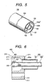
- FIG. 5 is a perspective view of the duplex pipe.
- the air conditioner for automobiles shown in FIG. 1 is a dual-type air conditioner used in so-called one-box cars etc., and there are provided an air conditioner 10 for mainly conditioning atmosphere around the front seat, and another air conditioner 20 for the rear seat.
- the air conditioner 20 for the rear seat is installed in the center or near the rear part within a passenger room.
- the evaporators Ef and Er function to cool the intake air by exchanging heat with a coolant which passes through the inside of the evaporators.
- Expansion valves Vf, Vr respectively reduces a pressure to make the coolant having low temperature and low pressure.
- the heater cores Hf, Hr function to heat the intake air by exchanging heat with heated cooling water for engine(s) which passes through the inside of the equipments.
- the front evaporator Ef, the rear evaporator Er, a compressor 31, a condenser 32, a liquid tank 33, the expansion valves Vf, Vr are connected through coolant lead pipes to form a cooling cycle.
- the liquid coolant at relatively high temperature and under high pressure flows out of the liquid tank 33 and is led to the front evaporator Ef and the rear evaporator Er through the coolant lead pipes 34, 35 branched in the engine room.
- gaseous coolant at relatively low temperature and under low pressure flows out of the front evaporator Ef and the rear evaporator Er respectively and passes through coolant lead pipes 36 and 37 and join together in the engine room before being sucked into the compressor 31.
- duplex pipes are used as coolant lead pipes for connecting the rear evaporator Er with the cooling cycle.
- the duplex pipes comprise the first duplex pipe 100 to be connected to the coolant lead pipes 35, 37 and the second duplex pipe 200 to be connected to the rear evaporator Er.
- Those two duplex pipes 100, 200 are connected with each other via a joint 40 for duplex pipes.
- the low-pressure gaseous coolant (corresponding to the first fluid) flows through the outer pipes 101, 201, while the high-pressure liquid coolant (corresponding to the second fluid) from the liquid tank 33 flows through the inner pipes 102, 202.
- the outer pipe 101 is connected to the coolant lead pipe 37 and the inner pipe 102 to the coolant lead pipe 35 respectively by a joint 50.
- the outer pipe 201 is connected to the outlet pipe 24 of the rear evaporator Er, and the inner pipe 202 to the expansion valve inlet pipe 25 respectively via the joint 60.
- the first duplex pipe 100 is integrally molded or drawn out of an aluminum material and is formed of an outer pipe 101, an inner pipe 102 and connecting ribs 103 for connecting the outer pipe 101 and the inner pipe 102.
- the outside diameter of the outer pipe 101 is ⁇ 16 to 25 mm while the outside diameter of the inner pipe 102 is about ⁇ 6 to 12 mm.
- the connecting ribs 103 are provided in such a way as to radiially divide the space formed between the outer pipe 101 and the inner pipe 102 into three separate spaces. Since three connecting ribs 103 are present, the axial bending balance is asured, which provides higher degree of freedom on bending design.
- the second duplex pipe 200 is formed similarly, and will not be explained in detals.
- duplex pipes 100, 200 are used as coolant lead pipes for connecting the rear evaporator Er with the cooling cycle, the following advantages are offered over separately providing each of the coolant lead pipe for a low-pressure coolant and another coolant lead pipe for a high-pressure coolant. That is, since the bending stiffness becomes higher, restrictions such as bending rate in manufacture are relieved, and consequently the productivity is improved.
- a conventional pair of pipelines can now be replaced with one single pipe which is manufactured by substantially about half number of machining steps including bending, which reduces the processing costs.
- the pipe Since the stiffness becomes higher, the pipe is hard to be deformed during transport or mounting operations on the car body, and furthermore since it is unnecessary to fix one coolant lead pipe to the other coolant lead pipe utilizing a bracket, the cost is reduced and also the workability in mounting the pipe on the car body is improved.
- the joint 40 for duplex pipes is classified as a joint of the flange type and, in essence, has a first outer pipe seal unit 110 mounted on the outer pipe end portion 101a of the first duplex pipe 100, a second outer pipe seal unit 210 mounted on the outer pipe end portion 201a of the second duplex pipe 200, a first inner seal portion 120 formed on the inner pipe end portion 102a of the first duplex pipe 100, a second inner pipe seal portion 220 formed on the inner pipe end portion 202a of the second duplex pipe 200, a seal member 300 for the outer pipe disposed between the first outer pipe seal unit 110 and the second outer pipe seal unit 210 to prevent leakage of low-pressure gaseous cooling medium, and a sealing member 400 for the inner pipe disposed between the first inner seal portion 120 and the second inner pipe seal portion 220.
- the joint 40 for duplex pipes has a connection structure 500 for connecting two duplex pipes 100, 200.
- the first inner seal portion 120 has such a configuration as to be in engagement with the second inner pipe seal portion 220.
- the sealing member 300 for the outer pipe includes an O-ring 301, and the sealing member 400 for the inner pipe also includes an O-ring 401.
- the connection structure 500 is formed of a through bolt 501 and a nut 502.
- the clearance between the first outer pipe seal unit 110 and the second outer pipe seal unit 210 is defined as larger than that existing between the first inner seal portion 120 and the second inner pipe seal portion 220.
- the first outer pipe seal unit 110 has a base 111 to be soldered to the outer pipe end portion 101a, an annular projection 112 protruding from the base 111 and a flange 113 continuously provided on the lower side in the drawing of the base 111.
- a ring groove 114 Around the outer circumferential surface of the annular projection 112, there is formed a ring groove 114 in which the O-ring 301 is inserted.
- the second outer pipe seal unit 210 as shown in FIGs.
- FIG. 4A and 4B has a base 211 to be soldered to the outer pipe end portion 201a, an annular depression 212 defining a depressed part in the base 211, and a flange 213 continuously provided on the lower side in the drawing of the base 211.
- the annular projection 112 is fit into the annular depression 212.
- the first inner seal portion 120 has an widened flared portion 121.
- This flared portion 121 is formed by flaring the inner pipe end portion 102a by punching.
- the second inner pipe seal portion 220 as shown in FIG. 4A, has a ring groove 221 formed to insert the O-ring 401 for the inner pipe.
- the ring groove 221 is formed by punching or rolling the inner pipe end portion 202a.
- the length of the first inner seal portion 120 is defined as such a manner that its farthermost edge does not protrude out of the end edge of the first outer pipe seal unit 110, and the length of the second inner pipe seal portion 220 is also defined as such a manner that its farthermost edge does not protrude out of the end edge of the second outer pipe seal unit 210.
- deviation may occur in machining the outer pipe end portions 101a, 201a or the inner pipe end portion 102a, 202a and in soldering the outer pipe seal units 110, 210, and it is virtually impossible to bring the deviation in concentricity to zero.
- the clearance between the outer pipe seal units 110 and 210 is defined larger than that of the inner seal portions 120, 220 by a specific distance so that the differences in concentricity caused in the respective duplex pipes 100, 200 between the outer pipe seal units 110 and 210 and between the inner seal portions 120 and 220 can be absorbed by larger clearance between the outer pipe seal unit 110 and 210.
- the above described specific distance can be defined as desired, for example, at about 0.2 mm.
- the wire diameter ( ⁇ out) of the O-ring 301 for the outer pipe becomes larger than the wire diameter ( ⁇ in) of the O-ring 401 for the inner pipe so as to reduce the range of compression rate of the O-ring 301 for the outer pipe.
- the wire diameter ( ⁇ out) of the O-ring 301 for the outer pipe becomes larger, it is conceivable that the workability would decrease in inserting into the annular depression 212 the annular projection 112 with the O-ring 301 for the outer pipe placed therein. In such a case, therefore, it is desirable that the hardness of the O-ring 301 for the outer pipe is set lower than the hardness of the O-ring 401 for the inner pipe so that insertion of the O-ring 301 for the outer pipe is facilitated due to elastical deformation.
- the second inner pipe seal portion 220 is mated with the flared portion 121 of the first inner seal portion 120.
- the O-ring 301 for the outer pipe is placed between the first outer pipe seal unit 110 and the second outer pipe seal unit 210, and the O-ring 401 for the inner pipe is placed between the first inner seal portion 120 and the second inner pipe seal portion 220 as well.
- the through bolt 501 is inserted into the ports (openings) 115, 215 on the respective flanges 113, 213 and the nut 502 is screwed up, completing the connecting of the two duplex pipes 100, 200.
- the wire diameter ( ⁇ out) of the O-ring 301 for the outer pipe is defined larger than the wire diameter ( ⁇ in) of the O-ring 401 for the inner pipe, the rate of compression of the O-ring 301 for the outer pipe is reduced, the leakage through the mating surfaces of the outer pipe seal units 110, 210, where the clearance is defined relatively large can be completely prevented.
- the joint 40 for duplex pipes is a joint of the flange type. Therefore, because the outer pipes 101, 201 and the inner pipes 102, 202 can be mutually connected to simultaneously by one tightening step of tightening the nut 502 on the through bolt 501, the procedures for connecting the two duplex pipes 100, 200 are simplified.
- the place where leakage could be caused is only one place between the outer pipe seal units 110, 210, and thus the reliability in preventing leakage rises. Furthermore, as welding becomes unnecessary the possible occurrence of the coolant leakage due to faulty welding practice is eliminated and the reliability in preventing leakage is further increased.
- the inner pipes 102, 202 function as passageway for the high-pressure cooling medium and the outer pipes 101, 201 are intended as passageway for the low-pressure cooling medium, a passageway on the low-pressure side which requires a relatively large sectional area can be secured easily.
- heat exchange readily takes place between the high-temperature, high-pressure cooling medium leading to the expansion valve Vr and the low-temperature, low-pressure cooling medium flowing out of the rear evaporator Er, the temperature of the cooling medium leading to the expansion valve Vr become lowered, and the performance of the rear evaporator Er is improved to realize the power saving.
- the passageway for the high-pressure cooling medium is located inside, and therefore, even if the pressure rises abnormally and the high-pressure cooling medium leaks from the inner pipes 102, 202, the leaked high-pressure cooling medium is maintained within the outer pipes 101, 201.
- a slit 104 is formed in the outer circumferential surface 102a of the inner pipe 102 along a circumferential line which corresponds to the exposure length of the inner pipe 102 distant from the end of the duplex pipe. Then, the connecting ribs 103 connecting the outer circumferential surface of the inner pipe are cut at the lower ends from the end of the duplex pipe in the axial direction. For this, a cutting tool is used that moves along the axial direction while turning around the inner circumferential surface 102b of the inner pipe as a guide.
- this cutting tool turns around the inner circumferential surface of the inner pipe as guide, it enables to cut the connecting rib 103 in the axial direction while the wall thickness of the inner pipe 102 kept uniform even if the position of the inner pipe 102 is shifted in the radial direction.
- the connecting rib 103 has been cut up to the slit 104, the outer pipe 101 and the connecting ribs 103 can be removed from the inner pipe 102 exposing specified part of the inner pipe 102.
- burrs are formed at the end portion of the outer pipe after the outer pipe and the inherent part of the connecting ribs is removed, and finishing work is required to remove the burrs.
- a slit 104 is cut in advance as described in the embodiment, no burrs are formed at the outer pipe end portion 101a eliminating redundant finishing work, simplifying the processing work thereby.
- the exposed inner pipe end portion 102a is flared by punching to form the first inner seal portion 120 having the flared portion 121.
- the second duplex pipe 200 is processed likewise to have part of the inner pipe 202 exposed, and the inner pipe end portion 202a is punched or rolled to form a second inner pipe seal portion 220 having a ring groove 221.
- the wall thickness of the exposed inner pipe end portion was not made uniform, and the inner pipe end portion could be cracked in punching operations. Therefore, it was impossible to punch in practice.
- the connecting rib 103 is removed by the cutting tool utilizing the inner circumferential surface 102b of the inner pipe as guide as described in the embodiment, the inner pipe 102 is uniform in wall thickness, which permits punching etc. Therefore, the processing of the inner pipe end portions 102a, 202a can be done quickly and in a simple manner as compared with the conventional processing method.
- a grooved portion 214 around the inner circumferential surface at the end of the annular depression 212 of the second outer pipe seal unit 210.
- the O-ring 301 for the outer pipe is present under a primary compression (temporarily held) in the initial fittingstage. Then, when the two are mated together, the O-ring 301 for the outer pipe lies under a secondary compression (normal fitting).
- the forming position of the ring groove 221 may be located in the distal end of the inner pipe end portion 202a. That improves workability in fixing or removing the O-ring 401 for the inner pipe on the ring groove 221 located near the end. Furthermore, since it is so arranged that before the O-ring 301 for the outer pipe is compressed, the O-ring 401 for the inner pipe will be compressed, which can disperse the inserting force and improve the inserting workability. In addition, in view of improving the inserting workability, the same can be achieved by slightly increasing the clearance between the first inner seal portion 120 and the second inner pipe seal portion 220 and by increasing wire diameter of the O-ring 401 for the inner pipe.
- the joint 41 for duplex pipes has a first outer pipe seal unit 130 holding the O-ring 301 for the outer pipe to be mounted on the outer pipe end portion 101a, a second outer pipe seal unit 230 to be fixed on the outer pipe end portion 201a, a union screw 503 formed on the outer circumferential surface of the second outer pipe seal unit 230 and a union screw 504 inserted in the first duplex pipe 100.
- a connection structure 500 is includes a union screws 503 and 504 to be connected thereto.
- both the O-ring 301 for the outer pipe and the O-ring 401 for the inner pipe may be provided in one duplex pipe (in the shown example, on the first duplex pipe 100).
- the joint for duplex pipes provides simplified connecting procedure achieving reliability in preventing leakage.
- the joint for duplex pipes successfully maintaines the workability in connecting the first and the second outer pipe seal units even if the O-ring, which functions as a sealing member for the outer pipe, is increased in wire diameter.
Landscapes
- Engineering & Computer Science (AREA)
- Mechanical Engineering (AREA)
- Physics & Mathematics (AREA)
- Thermal Sciences (AREA)
- General Engineering & Computer Science (AREA)
- Quick-Acting Or Multi-Walled Pipe Joints (AREA)
- Gasket Seals (AREA)
- Flanged Joints, Insulating Joints, And Other Joints (AREA)
Claims (11)
- Verbindung zum Verbinden eines ersten Duplex- Rohres (100) mit einem zweiten Duplex- Rohr (200), wobei jedes der ersten und zweiten Duplex- Rohre (100, 200) ein Außenrohr (101, 201), um ein erstes Fluid durchzuleiten, und ein Innenrohr (102, 202), angeordnet innerhalb des Außenrohres (101, 201), enthält, wobei das Innenrohr (102, 202) zum Durchleiten eines zweiten Fluids dient und die Verbindung (40, 41) aufweist:eine erste Außenrohr- Abdichteinheit (110, 130), verbunden mit einem Ende (101 a) des Außenrohres (101) des ersten Duplex- Rohres (100);eine zweite Außenrohr- Abdichteinheit (210, 230), verbunden mit einem Ende (201 a) des Außenrohres (201) des zweiten Duplex- Rohres (200);einen ersten Innenrohr- Abdichtabschnitt (120), gebildet an einem Ende (102a) des Innenrohres (102) des ersten Duplex- Rohres (100);einen zweiten Innenrohr- Abdichtabschnitt (220), gebildet an einem Ende (202a) des Innenrohres (202) des zweiten Duplex- Rohres (200);ein erstes Dichtungsteil (300), angeordnet zwischen der ersten Außenrohr- Abdichteinheit (110, 130) und der zweiten Außenrohr- Abdichteinheit (210, 230), wobei das erste Dichtungsteil (300) zum Abdichten der Außenrohre (101, 101) dient, um die Leckage des ersten Fluids zu verhindern;ein zweites Dichtungsteil (400), angeordnet zwischen dem ersten Innenrohr- Abdichtabschnitt (120) und dem zweiten Innenrohr- Abdichtabschnitt (220), wobei das zweite Dichtungsteil (400) zum Abdichten der Innenrohre (101, 101) vorgesehen ist, um die Leckage des zweiten Fluids zu verhindern; undeinen Verbindungsaufbau (500), um das erste und zweite Duplex- Rohr (100, 200) unter einer Bedingung zu verbinden, dass das erste Dichtungsteil (300) zwischen der ersten Außenrohr- Abdichteinheit (110, 130) und der zweiten Außenrohr- Abdichteinheit (210, 230) angeordnet ist, und das zweite Dichtungsteil (400) zwischen dem ersten Innenrohr- Abdichtabschnitt (120) und dem zweiten Innenrohr- Abdichtabschnitt (220) angeordnet ist, wobeiein Spalt zwischen der ersten Außenrohr- Abdichteinheit (110, 130) und der zweiten Außenrohr- Abdichteinheit (210, 230) größer als ein Spalt zwischen dem ersten Innenrohr- Abdichtabschnitt (120) und dem zweiten Innenrohr- Abdichtabschnitt (220) gebildet ist, wobei der erste Innenrohr- Abdichtabschnitt (120) mit dem zweiten Innenrohr- Abdichtabschnitt (220) im Eingriff ist, undsowohl die erste Außenrohr- Abdichteinheit (110, 130) als auch die zweite Außenrohr- Abdichteinheit (210, 230) in die andere der ersten Außenrohr- Abdichteinheit (110, 130) und die zweite Außenrohr- Abdichteinheit (210, 230) eingesetzt ist, undsowohl der erste Innenrohr- Abdichtabschnitt (120) als auch der zweite Innenrohr-Abdichtabschnitt (220) in den anderen des ersten Innenrohr- Abdichtabschnittes (120) und des zweiten Innenrohr- Abdichtabschnittes (220) eingesetzt ist.
- Verbindung nach Anspruch 1, wobei der Spalt zwischen der ersten Außenrohr-Abdichteinheit (110, 130) und der zweiten Außenrohr- Abdichteinheit (210, 230) und der Spalt zwischen dem ersten Innenrohr- Abdichtabschnitt (120) und dem zweiten Innenrohr- Abdichtabschnitt (220) jeweils als ein konzentrischer Spalt gebildet wird.
- Verbindung nach Anspruch 1 oder 2, wobei das erste Dichtungsteil (300) und das zweite Dichtungsteil (400) O- Ringe (301, 401) sind.
- Verbindung nach Anspruch 3, wobei die radiale Dicke des O- Ringes (301) für die Außenrohre (101, 201) größer als die des O- Rings (401) für die Innenrohre (102, 202) ist.
- Verbindung nach Anspruch 3 oder 4, wobei die Härte des O- Ringes (301) für die Außenrohre (101, 201) geringer als die des O- Ringes (401) für die Innenrohre (102, 202) ist.
- Verbindung nach zumindest einem der Ansprüche 3 bis 5, wobei eines der Innenrohre (102, 202) eine Nut (221) zum Unterbringen des O- Ringes (401) bildet.
- Verbindung nach zumindest einem der Ansprüche 3 bis 6, wobei eine der ersten Außenrohr- Abdichteinheit (110, 130) oder der zweiten Außenrohr- Abdichteinheit (210, 230) eine Nut (114) zum Unterbringen des O- Ringes (301) bildet.
- Verbindung nach zumindest einem der Ansprüche 1 bis 7, wobei ein Schraube (501) und eine Mutter (502) den Verbindungsaufbau (500) bilden.
- Verbindung nach Anspruch 8, wobei die Schraube (501) in die erste Außenrohr-Abdichteinheit (110) und die zweite Außenrohr- Abdichteinheit (210) eingesetzt ist, um die erste Außenrohr- Abdichteinheit (110) an der zweiten Außenrohreinheit (101) zu befestigen.
- Verbindung nach zumindest einem der Ansprüche 1 bis 7, wobei die erste Außenrohr- Abdichteinheit (130) einen Verbindungs- Mutternabschnitt (504) hat und die zweite Außenrohr- Abdichteinheit (230) einen Verbindungs- Schraubenabschnitt (503) hat, der mit dem Verbindungs- Mutternabschnitt (504) der ersten Außenrohr- Abdichteinheit (110, 130) im Eingriff ist, um den Verbindungsaufbau (500) mit dem Verbindungs- Mutternabschnitt (504) und dem Verbindungs- Schraubenabschnitt (503) zu bilden.
- Verbindung nach zumindest einem der Ansprüche 1 bis 10, wobei das Außenrohr (101, 201) vorgesehen ist, um ein gasförmiges Niederdruck- Kühlmittel hindurchzuleiten, und das Innenrohr (102, 202) vorgesehen ist, ein flüssiges HochdruckKühlmittel hindurchzuleiten.
Applications Claiming Priority (2)
| Application Number | Priority Date | Filing Date | Title |
|---|---|---|---|
| JP2000047529 | 2000-02-24 | ||
| JP2000047529A JP4014349B2 (ja) | 2000-02-24 | 2000-02-24 | 二重管用継手 |
Publications (2)
| Publication Number | Publication Date |
|---|---|
| EP1128121A1 EP1128121A1 (de) | 2001-08-29 |
| EP1128121B1 true EP1128121B1 (de) | 2005-04-27 |
Family
ID=18569768
Family Applications (1)
| Application Number | Title | Priority Date | Filing Date |
|---|---|---|---|
| EP01104367A Expired - Lifetime EP1128121B1 (de) | 2000-02-24 | 2001-02-23 | Verbindung für doppelwandige Rohrleitungen |
Country Status (4)
| Country | Link |
|---|---|
| US (1) | US6533328B2 (de) |
| EP (1) | EP1128121B1 (de) |
| JP (1) | JP4014349B2 (de) |
| DE (1) | DE60110296T2 (de) |
Cited By (2)
| Publication number | Priority date | Publication date | Assignee | Title |
|---|---|---|---|---|
| DE102005022513A1 (de) * | 2005-05-11 | 2006-11-16 | Behr Gmbh & Co. Kg | Kältemittelleitungen für Klimageräte |
| DE202011005352U1 (de) | 2011-04-15 | 2011-12-12 | Matthias Möllenhoff | Druckkontrollierbares Doppelwandsystem mit Durchbruch und optionaler Rohranbindung |
Families Citing this family (22)
| Publication number | Priority date | Publication date | Assignee | Title |
|---|---|---|---|---|
| US20030028182A1 (en) * | 1999-04-21 | 2003-02-06 | Cryocath Technologies Inc. | Cryoablation catheter handle |
| JP5153915B2 (ja) * | 2000-03-31 | 2013-02-27 | カルソニックカンセイ株式会社 | 二重管端末加工方法および二重管端末加工装置 |
| JP3949484B2 (ja) * | 2002-03-27 | 2007-07-25 | カルソニックカンセイ株式会社 | 二重管用継手、二重管用継手と二重管とのろう付け方法 |
| EP1359358B1 (de) * | 2002-05-03 | 2006-06-14 | Dieter Bächle | Rohreinheit |
| US7753413B2 (en) | 2003-01-28 | 2010-07-13 | Denso Corporation | Vapour-compression type refrigerating machine and double pipe structure and double pipe joint structure preferably used therefor |
| JP4323181B2 (ja) * | 2003-02-17 | 2009-09-02 | カルソニックカンセイ株式会社 | 二重管用継手及びその製造方法 |
| DE10347676A1 (de) * | 2003-10-09 | 2005-05-04 | Behr Gmbh & Co Kg | Heizungskreislauf für ein Kraftfahrzeug |
| US7530602B2 (en) | 2005-01-17 | 2009-05-12 | Nippon Pillar Packing Co., Ltd. | Double-pipe joint |
| US7625014B2 (en) * | 2006-09-26 | 2009-12-01 | Alcon, Inc. | Dual fluid connector |
| US20080106095A1 (en) * | 2006-11-08 | 2008-05-08 | Harris Richard K | Heater core connector tube |
| JP5086840B2 (ja) * | 2008-02-29 | 2012-11-28 | カルソニックカンセイ株式会社 | 二重管接続構造および二重管接続方法 |
| JP4571703B1 (ja) * | 2009-09-02 | 2010-10-27 | 久雄 泉 | 家庭用ろ過湯貯湯槽装置 |
| DE102010020280A1 (de) | 2010-05-12 | 2011-11-17 | Linde Aktiengesellschaft | Wasserstoffinfrastruktur |
| KR101177803B1 (ko) | 2010-10-28 | 2012-08-30 | 삼성중공업 주식회사 | 페인트 호스 |
| SE536025C2 (sv) * | 2011-02-25 | 2013-04-02 | Kungsoers Plast Ab | Smältsvetsmuff |
| US9157557B2 (en) * | 2012-10-31 | 2015-10-13 | Xylem Water Solutions U.S.A., Inc. | Gas distribution assembly |
| FR3002612B1 (fr) * | 2013-02-28 | 2015-07-31 | Eurocopter France | Systeme de raccordement etanche d'un tuyau a double peau, et circuit hydraulique muni dudit systeme |
| US9151426B2 (en) * | 2013-08-28 | 2015-10-06 | Spears Manufacturing Co. | Closure fitting for containment piping |
| JP6127922B2 (ja) * | 2013-11-06 | 2017-05-17 | トヨタ自動車株式会社 | 燃料電池部品の挿入組み付け機構 |
| JP6379015B2 (ja) * | 2014-11-13 | 2018-08-22 | 有光工業株式会社 | 発泡洗浄装置 |
| CN205013934U (zh) * | 2015-08-27 | 2016-02-03 | 厦门建霖工业有限公司 | 管中管快速连接结构 |
| FR3128760A1 (fr) * | 2021-10-28 | 2023-05-05 | Airbus | Ensemble de connexion optimise entre deux portions d’une canalisation pour le transport d’un fluide cryogenique, comprenant une chambre d’isolation thermique additionnelle et une chambre d’expansion de fluide. |
Family Cites Families (19)
| Publication number | Priority date | Publication date | Assignee | Title |
|---|---|---|---|---|
| CA672802A (en) * | 1963-10-22 | Leupp Theodor | Plastic pipe lines | |
| US2850264A (en) * | 1953-09-18 | 1958-09-02 | Donovan B Grable | Dual passage concentric pipe drill string coupling |
| US2838074A (en) * | 1954-12-06 | 1958-06-10 | Borg Warner | Fluid pressure hose |
| GB1310513A (en) | 1969-07-01 | 1973-03-21 | Btr Industries Ltd | Union for two pairs of ducts |
| CA1034937A (en) | 1976-04-12 | 1978-07-18 | Floyd W. Becker | Double-walled pipe construction |
| US4108476A (en) * | 1977-04-11 | 1978-08-22 | Krupp Walter H | Precompressed piping system for handling cryogenic fluid |
| US4128127A (en) | 1977-09-23 | 1978-12-05 | Otis Engineering Corporation | Swivel connector |
| DE3603721C2 (de) * | 1985-08-20 | 1994-11-17 | Smc Kk | Kupplung für Mehrfachdurchlaßleitung |
| US4708371A (en) * | 1986-04-09 | 1987-11-24 | Pratt & Whitney Canada Inc. | Coupling for a fuel manifold |
| EP0268251B1 (de) * | 1986-11-18 | 1990-12-27 | Smc Corporation | Rohrkupplung für mehrwandige Rohrleitungen |
| FR2639702B1 (fr) * | 1988-11-25 | 1991-03-22 | Aerospatiale | Dispositif de raccordement etanche et demontable de deux tubes, notamment pour installation de transfert de carburant |
| US5184850A (en) * | 1989-07-07 | 1993-02-09 | Georg Fischer Ag | Method of connecting pipes of plastics material of a double pipe system and a pipe connection made by the method |
| US5088774A (en) | 1990-05-07 | 1992-02-18 | Tylan General, Inc. | Coupling for interconnection of coaxial tubing |
| US5547231A (en) | 1991-04-04 | 1996-08-20 | Sharp; Bruce R. | Fittings for use with double wall pipeline systems having support fins |
| GB2261042A (en) * | 1991-11-01 | 1993-05-05 | Guest John D | Improvements in or relating to tube couplings for co-axial tubing |
| US5265652A (en) | 1992-05-29 | 1993-11-30 | Couple-Up, Inc. | Multiaxial fuel transfer pipe system |
| FR2702241B1 (fr) | 1993-03-03 | 1995-06-02 | Gerard Sabatier | Tige de forage à double corps destinée à être mise en Óoeuvre dans les modes de forage dits "à circulation inverse". |
| US5931184A (en) * | 1997-06-10 | 1999-08-03 | Armenia; John G. | Safety hose for delivering water to an appliance |
| US6196596B1 (en) * | 1998-11-20 | 2001-03-06 | Illinois Tool Works Inc. | Quick connect/disconnect coaxial hose assembly |
-
2000
- 2000-02-24 JP JP2000047529A patent/JP4014349B2/ja not_active Expired - Fee Related
-
2001
- 2001-02-23 EP EP01104367A patent/EP1128121B1/de not_active Expired - Lifetime
- 2001-02-23 DE DE60110296T patent/DE60110296T2/de not_active Expired - Fee Related
- 2001-02-23 US US09/790,869 patent/US6533328B2/en not_active Expired - Fee Related
Cited By (3)
| Publication number | Priority date | Publication date | Assignee | Title |
|---|---|---|---|---|
| DE102005022513A1 (de) * | 2005-05-11 | 2006-11-16 | Behr Gmbh & Co. Kg | Kältemittelleitungen für Klimageräte |
| DE202011005352U1 (de) | 2011-04-15 | 2011-12-12 | Matthias Möllenhoff | Druckkontrollierbares Doppelwandsystem mit Durchbruch und optionaler Rohranbindung |
| DE102012006736A1 (de) | 2011-04-15 | 2012-10-18 | Berthold Lutter | Druckkontrollierbares Doppelwandsystem mit Durchbruch und optionaler Rohranbindung |
Also Published As
| Publication number | Publication date |
|---|---|
| US20010019208A1 (en) | 2001-09-06 |
| JP4014349B2 (ja) | 2007-11-28 |
| US6533328B2 (en) | 2003-03-18 |
| JP2001235080A (ja) | 2001-08-31 |
| EP1128121A1 (de) | 2001-08-29 |
| DE60110296T2 (de) | 2005-10-06 |
| DE60110296D1 (de) | 2005-06-02 |
Similar Documents
| Publication | Publication Date | Title |
|---|---|---|
| EP1128121B1 (de) | Verbindung für doppelwandige Rohrleitungen | |
| US6896298B2 (en) | Conduit coupling assembly | |
| US5354101A (en) | Sealing washer block connection | |
| EP2362934B1 (de) | Wärmetauscher mit einem verbesserten verbinder für einen klimaanlagenkreislauf eines kraftfahrzeugs | |
| CN1163720C (zh) | 辅助加热及空调系统的管组件 | |
| US6866090B2 (en) | Air conditioning apparatus for vehicle | |
| CN113167516B (zh) | 内部换热器及具有内部换热器的制冷循环装置 | |
| US6070659A (en) | External connection for heat exchanger unit | |
| JP5637422B2 (ja) | 冷却機械用内部熱交換器 | |
| US7753413B2 (en) | Vapour-compression type refrigerating machine and double pipe structure and double pipe joint structure preferably used therefor | |
| JP2001235081A (ja) | 二重管用継手 | |
| CN112937248A (zh) | 汽车空调同轴管的制作方法及汽车空调同轴管 | |
| US11365939B2 (en) | Sealed connection of a connector to a coaxial tubular heat exchanger | |
| CN116635168A (zh) | 压接管件装置 | |
| CN219103774U (zh) | 换热器 | |
| CN214839039U (zh) | 一种维修空调管路的连接装置 | |
| KR100484871B1 (ko) | 공기조화기의 냉매배관 연결장치 | |
| KR20250035906A (ko) | 다중 피치 스파이럴 유로의 열교환용 이중관 제조 방법 및 그 이중관 | |
| JP2021188786A (ja) | 内部熱交換器及び内部熱交換器の製造方法 | |
| KR20240111497A (ko) | 열교환용 이중관 제조 방법 | |
| JP2021188787A (ja) | 内部熱交換器の製造方法 | |
| WO2021241422A1 (ja) | 内部熱交換器及び内部熱交換器の製造方法 | |
| JP2021188788A (ja) | 内部熱交換器の製造方法 | |
| HK1149794A (en) | Heat exchanger coupling blocking plug |
Legal Events
| Date | Code | Title | Description |
|---|---|---|---|
| PUAI | Public reference made under article 153(3) epc to a published international application that has entered the european phase |
Free format text: ORIGINAL CODE: 0009012 |
|
| AK | Designated contracting states |
Kind code of ref document: A1 Designated state(s): DE FR GB Kind code of ref document: A1 Designated state(s): AT BE CH CY DE DK ES FI FR GB GR IE IT LI LU MC NL PT SE TR |
|
| AX | Request for extension of the european patent |
Free format text: AL;LT;LV;MK;RO;SI |
|
| 17P | Request for examination filed |
Effective date: 20020220 |
|
| AKX | Designation fees paid |
Free format text: DE FR GB |
|
| 17Q | First examination report despatched |
Effective date: 20030502 |
|
| GRAP | Despatch of communication of intention to grant a patent |
Free format text: ORIGINAL CODE: EPIDOSNIGR1 |
|
| RTI1 | Title (correction) |
Free format text: JOINT FOR DOUBLE WALLED, DUPLEX, PIPES |
|
| GRAS | Grant fee paid |
Free format text: ORIGINAL CODE: EPIDOSNIGR3 |
|
| GRAA | (expected) grant |
Free format text: ORIGINAL CODE: 0009210 |
|
| AK | Designated contracting states |
Kind code of ref document: B1 Designated state(s): DE FR GB |
|
| REG | Reference to a national code |
Ref country code: GB Ref legal event code: FG4D |
|
| REF | Corresponds to: |
Ref document number: 60110296 Country of ref document: DE Date of ref document: 20050602 Kind code of ref document: P |
|
| PLBE | No opposition filed within time limit |
Free format text: ORIGINAL CODE: 0009261 |
|
| STAA | Information on the status of an ep patent application or granted ep patent |
Free format text: STATUS: NO OPPOSITION FILED WITHIN TIME LIMIT |
|
| ET | Fr: translation filed | ||
| 26N | No opposition filed |
Effective date: 20060130 |
|
| PGFP | Annual fee paid to national office [announced via postgrant information from national office to epo] |
Ref country code: DE Payment date: 20090219 Year of fee payment: 9 |
|
| PGFP | Annual fee paid to national office [announced via postgrant information from national office to epo] |
Ref country code: GB Payment date: 20090217 Year of fee payment: 9 |
|
| REG | Reference to a national code |
Ref country code: GB Ref legal event code: 746 Effective date: 20090924 |
|
| PGFP | Annual fee paid to national office [announced via postgrant information from national office to epo] |
Ref country code: FR Payment date: 20090213 Year of fee payment: 9 |
|
| GBPC | Gb: european patent ceased through non-payment of renewal fee |
Effective date: 20100223 |
|
| REG | Reference to a national code |
Ref country code: FR Ref legal event code: ST Effective date: 20101029 |
|
| PG25 | Lapsed in a contracting state [announced via postgrant information from national office to epo] |
Ref country code: FR Free format text: LAPSE BECAUSE OF NON-PAYMENT OF DUE FEES Effective date: 20100301 |
|
| PG25 | Lapsed in a contracting state [announced via postgrant information from national office to epo] |
Ref country code: DE Free format text: LAPSE BECAUSE OF NON-PAYMENT OF DUE FEES Effective date: 20100901 |
|
| PG25 | Lapsed in a contracting state [announced via postgrant information from national office to epo] |
Ref country code: GB Free format text: LAPSE BECAUSE OF NON-PAYMENT OF DUE FEES Effective date: 20100223 |