EP1128152A2 - Système lançeur pour charges fumigènes et explosives monté sur un véhicule de combat - Google Patents
Système lançeur pour charges fumigènes et explosives monté sur un véhicule de combat Download PDFInfo
- Publication number
- EP1128152A2 EP1128152A2 EP01103145A EP01103145A EP1128152A2 EP 1128152 A2 EP1128152 A2 EP 1128152A2 EP 01103145 A EP01103145 A EP 01103145A EP 01103145 A EP01103145 A EP 01103145A EP 1128152 A2 EP1128152 A2 EP 1128152A2
- Authority
- EP
- European Patent Office
- Prior art keywords
- throwing
- cup
- frame part
- rotation
- vehicle
- Prior art date
- Legal status (The legal status is an assumption and is not a legal conclusion. Google has not performed a legal analysis and makes no representation as to the accuracy of the status listed.)
- Granted
Links
- 239000002360 explosive Substances 0.000 title claims abstract description 4
- 239000000779 smoke Substances 0.000 title 1
- 230000001154 acute effect Effects 0.000 claims abstract description 3
- 230000001360 synchronised effect Effects 0.000 claims description 3
- 230000005484 gravity Effects 0.000 claims description 2
- 239000003380 propellant Substances 0.000 claims description 2
- 238000000418 atomic force spectrum Methods 0.000 description 1
- 238000010276 construction Methods 0.000 description 1
- 230000001419 dependent effect Effects 0.000 description 1
- 238000011161 development Methods 0.000 description 1
- 230000018109 developmental process Effects 0.000 description 1
- 238000010304 firing Methods 0.000 description 1
- 238000009434 installation Methods 0.000 description 1
- 238000000034 method Methods 0.000 description 1
- 230000007935 neutral effect Effects 0.000 description 1
- 238000001931 thermography Methods 0.000 description 1
Images


Classifications
-
- F—MECHANICAL ENGINEERING; LIGHTING; HEATING; WEAPONS; BLASTING
- F41—WEAPONS
- F41F—APPARATUS FOR LAUNCHING PROJECTILES OR MISSILES FROM BARRELS, e.g. CANNONS; LAUNCHERS FOR ROCKETS OR TORPEDOES; HARPOON GUNS
- F41F1/00—Launching apparatus for projecting projectiles or missiles from barrels, e.g. cannons; Harpoon guns
- F41F1/08—Multibarrel guns, e.g. twin guns
-
- F—MECHANICAL ENGINEERING; LIGHTING; HEATING; WEAPONS; BLASTING
- F41—WEAPONS
- F41A—FUNCTIONAL FEATURES OR DETAILS COMMON TO BOTH SMALLARMS AND ORDNANCE, e.g. CANNONS; MOUNTINGS FOR SMALLARMS OR ORDNANCE
- F41A27/00—Gun mountings permitting traversing or elevating movement, e.g. gun carriages
- F41A27/06—Mechanical systems
- F41A27/08—Bearings, e.g. trunnions; Brakes or blocking arrangements
Definitions
- the invention relates to a throwing system arranged on a combat vehicle for fog candles, explosive devices and the like (e.g. IR fog, soft kill and Flares) with at least one on the outside of the vehicle by means of a Holder arranged cup support block, in the under a predetermined, the elevation of the throwing system determining angle to the bottom surface of the cup support block at least one throwing cup is inserted from the throwing body can be fired by means of a propellant charge.
- fog candles, explosive devices and the like e.g. IR fog, soft kill and Flares
- Throwing systems of this type are known per se and throwing cups for such throwing systems are for example in DE 24 20 862 A1, DE 37 06 213 A1 and AT 330 030.
- the Throwing cup individually or within a fixed holder to several rigidly on Vehicle attached.
- these are below predetermined fixed angles in azimuth aligned so that shot bodies shot from the various cups in a fan shape can be, but a change in the direction in which these subjects are shot down only by turning the combat vehicle accordingly or the combat vehicle tower is possible.
- a throwing system is also known in which several throwing cups are in parallel are fixed to each other in a frame-like holder, which as a whole is arranged in azimuth pivotable on the vehicle. With this throwing system a fan-shaped launch is only possible by throwing the projectile in time intervals are shot and between the individual shooting processes the entire holder of the throwing cup is pivoted in azimuth becomes. This has tactical disadvantages. Furthermore, this is known The structure is relatively large in construction and heavy in the silhouette of the combat vehicle can be integrated.
- the invention has for its object a throwing system with the input and to design the features specified in the preamble of patent claim 1, that the individual throwing cups can be aligned such that a fan-shaped Firing projectiles at the same time is possible and the Alignment of this subject can be changed without the combat vehicle or the combat vehicle tower has to be turned.
- the basic idea of the invention is that of several in general Throwing cup either in a common cup support block or inside to arrange a frame part assigned to each cup and the Cup carrier block or the frame part in azimuth can be turned on the vehicle store so that each throw cup from a drive device in the desired Direction is pivotable in azimuth. Because when you shoot one Throwing body considerable recoil forces, it has for stability the throwing system proved to be very advantageous when the cup carrier block with the throwing cup is arranged in such a way that the The axis of action of the throwing cup intersects the axis of rotation of the frame part. On in this way, moments acting on the directional drive are avoided.
- the stability of the throwing system can be increased in that everyone Cup carrier block or any frame part in the firmly connected to the vehicle Bracket at two points on the axis of rotation, each below the cup support block and is stored above the throwing cup. It turned out to be cheap also proven if the center of mass of the cup carrier block and Throwing cup is on or in the immediate vicinity of the axis of rotation.
- the control of the throwing system according to the invention can be carried out automatically Sensors, periscope, camera or thermal imaging device are done or manually via a tip sight or a sector switch.
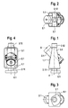
- a throwing system is shown that a throwing cup 2.1 has a known design that is used in a cup support block 1.1 is that its axis of action 5 at a predetermined acute angle runs to the bottom surface of the cup support block 1.1. This angle is fixed predefined and determines the elevation angle of the throwing cup.
- Cup carrier block 1.1 and throwing cup 2.1 are together firmly in a frame part 3.1 attached.
- the frame part 3.1 comprises the cup support block 1.1 on the bottom surface, the side surfaces and above the top so that the throw cup 2.1 is included.
- a hollow shaft 3.11 or 3.12 is arranged, the mutually aligned Axes the axis of rotation 4 of the frame part 3.1 described in more detail below determine.
- At the free end of the lower hollow shaft 3.11 is a, below explained, toothed segment 6.1 attached.
- the throwing cup 2.1 and the frame part 3.1 are arranged relative to one another, that the active axis 5 and the axis of rotation 4 intersect and the center of mass of cup support block 1.1 and throw cup 2.1 on the axis of rotation 4 of the frame part 3.1.
- cup carrier block 1.1 throwing cup 2.1 and frame part 3.1 existing unit can now in different In this way, it is assembled into a throwing installation comprising several such units become.
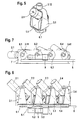
- the throwing system according to FIGS. 7 to 11 consists of four units according to FIG. 1 to 5, which are arranged side by side and each a cup support block 1.1 to 1.4, a throwing cup 2.1 to 2.4, a frame part 3.1 to 3.4 with hollow shafts 3.11 to 3.41 and 3.12 to 3.42. On the lower hollow shafts tooth segments 6.1 to 6.4 are attached in each case. These units are in a bracket 7 rotatably mounted.
- the bracket 7 has one U-shaped shape such that the units are each with the lower Hollow shafts 3.11 to 3.41 and the upper hollow shafts 3.12 to 3.42 such are rotatably mounted in the holder 7 that the axes of rotation 4 parallel to each other run and each unit in the bracket at two points on the axis of rotation each below the cup support block and above the throw cup is stored.
- the tooth segments attached to the lower hollow shafts 6.1 to 6.4 are located below the bottom of the bracket 7 and engage in one a rack 8 guided along the underside, which is not specifically there is shown displaceably mounted with respect to the holder 7. In the Rack 8 also engages the output pinion 9.1 of a fixed arrangement Gear motor 9 a.
- the operation of the Gear motor 9, the rack 8 displaced in its longitudinal direction and thereby are the frame parts 3.1 to 3.4 over the tooth segments 6.1 to 6.4 rotated about their respective axis of rotation 4 (Fig. 1). 7 to 11 as well can be seen, the frame parts 3.1 to 3.4 in the holder 7th arranged that the effective axes 5 (Fig. 1) of the throwing cup 2.1 to 2.4 each enclose a constant angle in azimuth with each other. That angle can be, for example, 12 °.
- the angle that each throw cup 2.1 to 2.4, starting from its zero position, is for example 220 ° azimuth. 9 and 11 show the two end positions of the throwing cup 2.1 to 2.4.
- the holder 7 with the units containing the throwing cups 2.1 to 2.4, is placed on a combat vehicle in such a way that the bottom of the Bracket 7 lies horizontally on the vehicle. Examples of this are shown in FIG. 17 and 18th
- FIG. 17 shows a battle tank KP1 with a schematic representation rotatable tower T, on its side walls on both sides of the longitudinal central axis L each a litter WA1.1 and WA1.2 is arranged.
- These throwing systems can have throwing bodies in on both sides of the vehicle a fan angle of 210 ° in total.
- Fig. 18 Here is a light Main battle tank KP2 a throwing system WA2 arranged at the rear of the vehicle, with which a fan angle of 200 ° can be reached in the direction of travel.
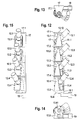
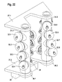
- FIGS. 12 to 16 Another possibility for the arrangement of those shown in FIGS. 1 to 5 Units in a common throwing system are shown in FIGS. 12 to 16.
- this throwing system there are four, each made of throwing cups 12.1 to 12.4, cup carrier blocks 11.1 to 11.4 and frame parts 13.1 to 13.4 existing Units one above the other in a manner not shown vertically on one Vehicle-mounted bracket 17 mounted so that the axes of rotation (reference number 4 in Fig. 1) of the frame parts 13.1 to 13.4 are aligned with one another.
- the Bracket 17 has mounting brackets 17.1 to one above the other 17.5, between which the individual units are arranged and on which the Hollow shafts 13.12 (Fig. 12) to 13.41 (Fig. 14) are mounted.
- each the upper hollow shaft of one frame part with the lower hollow shaft of the next coupled higher frame part.
- the lowest hollow shaft 13.41 carries a tooth segment 16.4, in which the output pinion 19.1 of a gear motor 19 engages. 13 to 16, the units are in the holder 17 arranged such that the throwing cups 12.1 to 12.4 in azimuth each enclose a fixed angle of 12 °.
- the geared motor 19 When actuated of the geared motor 19 are the frame parts over the toothed segment 16.4 13.1 to 13.4 and with them the throwing cups 12.1 to 12.4 synchronously around each twisted the same angle in azimuth.
- each frame part 3.1 to 3.4 or 13.1 to 13.4 from the zero position of the Angular range encompassing azimuth positions in a transport position is pivotable, in which the throwing cup 2.1 to 2.4 or 12.1 to 12.4 within a predetermined vehicle contour.
- cup carrier block, throwing cup and frame part do not exist Units are put together, but rather several throwing cups are arranged one above the other in a columnar cup support block, wherein the cup carrier blocks as a whole in the bracket fixed to the vehicle are rotatably mounted and each of these cup carrier blocks from the drive device is driven.
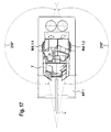
- FIG. 19 and 20 show a first embodiment, in which in the Vehicle arranged bracket 27.1 and 27.2 three cup support blocks 21.1 to 21.3 are rotatably mounted.
- the cup support block 21.1 carries the one above the other arranged throwing cup 22.1 and 22.2
- the cup support block 21.2 carries the stacked cups 22.3 and 22.4
- the cup support block 21.3 the stacking cups 22.5 and 22.6 wearing.
- the cup carrier blocks bear below the underside of the holder 27.2 21.1 to 21.3 each tooth segments 26.1 to 26.3.
- the axes of rotation of the cup support blocks 21.1 to 21.3 run vertically and parallel to each other.
- Everyone Cup support block 21.1 to 21.3 is above at two points on the axis of rotation and stored below the throwing cup.
- the tooth segments 26.1 to 26.3 grip into a rack 28 guided along the underside, which is opposite there the lower bracket 27.2 is slidably mounted. In the rack 28 also engages the output pinion of a fixed gear motor 29 a. When the geared motor 29 is operating, the rack 28 is displaced and thereby tooth segments 26.1 to 26.3 are rotated, resulting in Rotation of the cup support blocks 21.1 to 21.3 leads.
- cup support blocks 31.1 or 31.2 carries four throwing cups 32.1 to 32.4 or 32.5 to 32.8. How can be read from the drawings in each of the cup support blocks 31.1 and 31.2 the throwing cups by a predetermined fixed angular amount in azimuth offset from each other.
- the cup support blocks 31.1 and 31.2 are with tooth segments arranged below the lower mounting part 27.2 36.1 or 36.2 connected to a sliding rack 38 intervene, which are driven by an output pinion from the geared motor 39 becomes.
- there is a synchronous operation of the geared motor 39 Rotation of the two cup carrier blocks 31.1 and 31.2.
- FIGS. 19 to 22 can be used in an analogous manner, 17 and 18, arranged on a main battle tank as described with reference to FIGS his.
Landscapes
- Engineering & Computer Science (AREA)
- General Engineering & Computer Science (AREA)
- Toys (AREA)
- Manipulator (AREA)
- Disintegrating Or Milling (AREA)
- Body Structure For Vehicles (AREA)
- Fats And Perfumes (AREA)
- Passenger Equipment (AREA)
- Vehicle Step Arrangements And Article Storage (AREA)
Applications Claiming Priority (2)
| Application Number | Priority Date | Filing Date | Title |
|---|---|---|---|
| DE10008198 | 2000-02-23 | ||
| DE10008198A DE10008198A1 (de) | 2000-02-23 | 2000-02-23 | An einem Kampffahrzeug angeordnete Wurfanlage für Nebelkerzen, Sprengkörper u. dgl. |
Publications (3)
| Publication Number | Publication Date |
|---|---|
| EP1128152A2 true EP1128152A2 (fr) | 2001-08-29 |
| EP1128152A3 EP1128152A3 (fr) | 2004-05-19 |
| EP1128152B1 EP1128152B1 (fr) | 2006-05-17 |
Family
ID=7631932
Family Applications (1)
| Application Number | Title | Priority Date | Filing Date |
|---|---|---|---|
| EP01103145A Expired - Lifetime EP1128152B1 (fr) | 2000-02-23 | 2001-02-10 | Système lançeur pour charges fumigènes et explosives monté sur un véhicule de combat |
Country Status (8)
| Country | Link |
|---|---|
| US (1) | US20010015126A1 (fr) |
| EP (1) | EP1128152B1 (fr) |
| AT (1) | ATE326676T1 (fr) |
| AU (1) | AU1642301A (fr) |
| CA (1) | CA2333838C (fr) |
| DE (2) | DE10008198A1 (fr) |
| DK (1) | DK1128152T3 (fr) |
| ES (1) | ES2264948T3 (fr) |
Cited By (8)
| Publication number | Priority date | Publication date | Assignee | Title |
|---|---|---|---|---|
| WO2005033611A1 (fr) * | 2003-10-09 | 2005-04-14 | Elbit Systems Ltd. | Systeme d'armement multiple pour vehicule blinde |
| US7669513B2 (en) | 2003-10-09 | 2010-03-02 | Elbit Systems Ltd. | Multiple weapon system for armored vehicle |
| EP2219008A2 (fr) | 2009-02-14 | 2010-08-18 | Krauss-Maffei Wegmann GmbH & Co. KG | Système projecteur pour véhicules |
| EP2219009A2 (fr) | 2009-02-14 | 2010-08-18 | Krauss-Maffei Wegmann GmbH & Co. KG | Système lanceur destiné à projeter un agent non létal d'un véhicule, notamment un véhicule de police ou militaire |
| EP1457754B2 (fr) † | 2003-03-13 | 2013-03-20 | NEXTER Systems | Tourelleau multitube pour munition à haute énergie |
| EP2600097A1 (fr) | 2011-11-29 | 2013-06-05 | Nexter Munitions | Procédé de contrôle du déclenchement d'une charge militaire, dispositif de contrôle et fusée de projectile mettant en oeuvre un tel procédé |
| CN103925839A (zh) * | 2014-04-29 | 2014-07-16 | 成都陵川特种工业有限责任公司 | 一种灭火弹发射器 |
| RU2537071C1 (ru) * | 2013-10-29 | 2014-12-27 | Открытое акционерное общество "Завод им. В.А. Дегтярева" | Пусковая установка |
Families Citing this family (33)
| Publication number | Priority date | Publication date | Assignee | Title |
|---|---|---|---|---|
| GB0120181D0 (en) * | 2001-08-17 | 2009-07-22 | Bae Systems Plc | Projectile Storage and Launch Apparatus |
| DE102004017375B4 (de) * | 2004-04-08 | 2009-05-07 | Diehl Bgt Defence Gmbh & Co. Kg | System zum Schutze eines Zieles gegen angreifende Flugkörper |
| US7313995B2 (en) * | 2005-03-16 | 2008-01-01 | Lockheed Martin Corporation | Inclinable munitions launcher |
| DE102005020177A1 (de) | 2005-04-28 | 2006-11-02 | Rheinmetall Waffe Munition Gmbh | Wurfanlage |
| DE102006004992A1 (de) | 2006-02-01 | 2007-08-02 | Rheinmetall Waffe Munition Gmbh | Elektronik insbesondere für eine Wirkmittelwurfanlage |
| DE102006004954A1 (de) | 2006-02-01 | 2007-08-02 | Rheinmetall Waffe Munition Gmbh | Munitionsmagazin und damit ausgebildete Selbstschutz- Werfereinrichtung |
| DE102007029623A1 (de) | 2007-06-26 | 2009-02-26 | Rheinmetall Waffe Munition Gmbh | Wurfanlage mit Magazin |
| US7895788B1 (en) * | 2007-08-03 | 2011-03-01 | Enforcement Video, Llc | Ballistic tire-deflation device for security vehicles |
| DE102008038603C5 (de) | 2008-08-21 | 2018-04-19 | Krauss-Maffei Wegmann Gmbh & Co. Kg | Gegenschussanlage |
| GB0913637D0 (en) * | 2009-08-05 | 2009-09-16 | Chemring Countermeasures Ltd | Launcher |
| DE202011101266U1 (de) | 2011-05-23 | 2011-12-20 | Rheinmetall Waffe Munition Gmbh | Befestigungsvorrichtung für eine Werfereinheit |
| DE202011101269U1 (de) | 2011-05-23 | 2012-02-13 | Rheinmetall Waffe Munition Gmbh | Befestigungsvorrichtung für eine Werfereinheit |
| DE202012004430U1 (de) | 2012-05-08 | 2012-06-11 | Rheinmetall Waffe Munition Gmbh | Munitionsmagazin und damit ausgebildete Werfereinheit |
| DE102012010380B3 (de) | 2012-05-29 | 2013-01-31 | Rheinmetall Waffe Munition Gmbh | Kontakteinrichtung, insbesondere für eine Munition insbesondere in einem Werfer |
| US9074843B1 (en) * | 2012-10-05 | 2015-07-07 | Jerry R Montgomery | Payload delivery device |
| DE102013108822C5 (de) | 2013-08-14 | 2017-08-10 | Krauss-Maffei Wegmann Gmbh & Co. Kg | Waffe und Wurfkörper mit RFID-System |
| DE102015215893A1 (de) * | 2015-08-20 | 2017-02-23 | Robert Graf | Feuerwerks-Vorrichtung zum Erzeugen eines aus Einzeleffekten bestehenden Gesamteffektes |
| EP3458802B1 (fr) | 2016-05-17 | 2021-07-28 | Saab AB | Chargeur et cartouche |
| US10495424B2 (en) | 2016-05-17 | 2019-12-03 | Saab Ab | Magazine, cartridge and method for variable projectile cluster density of a countermeasure |
| US10696401B2 (en) | 2016-05-17 | 2020-06-30 | Saab Ab | Countermeasure dispenser with variable spoiler and method for launching a countermeasure |
| SE1651465A1 (en) * | 2016-05-17 | 2017-11-18 | Saab Ab | Firing direction limitation device |
| ES2886937T3 (es) * | 2016-05-17 | 2021-12-21 | Saab Ab | Cargador para el lanzamiento de contramedidas |
| KR102225616B1 (ko) * | 2016-09-20 | 2021-03-12 | 한화디펜스 주식회사 | 무장 제어 시스템 및 무장 제어 시스템의 제어 방법 |
| US10551147B1 (en) * | 2017-03-23 | 2020-02-04 | Combat Weapons Development Llc | Multi-barrel mortar launcher and method |
| RU182326U1 (ru) * | 2018-01-09 | 2018-08-14 | Общество с ограниченной ответственностью "Фирма МВЕН" | Устройство для распыления веществ с самолёта с помощью дымовых шашек |
| FR3105391B1 (fr) | 2019-12-24 | 2022-12-02 | Nexter Systems | Dispositif lanceur de munitions |
| DE102020119231B4 (de) | 2020-07-21 | 2022-07-21 | Krauss-Maffei Wegmann Gmbh & Co. Kg | Militärische Wurfanlage |
| DE102021107186A1 (de) | 2021-03-23 | 2022-09-29 | Krauss-Maffei Wegmann Gmbh & Co. Kg | Wurfkörpernachbildung |
| CN113324441B (zh) * | 2021-06-29 | 2025-01-07 | 北方长龙新材料技术股份有限公司 | 一种作战车炮塔外罩用烟雾弹基座及作战车炮塔外罩 |
| US12535305B2 (en) * | 2023-05-12 | 2026-01-27 | Ingram Enterprises, Inc. | Pyrotechnic mounting device |
| DE102024105507A1 (de) * | 2024-02-27 | 2025-08-28 | Rheinmetall Waffe Munition Gmbh | Getriebeeinheit zur Aufnahme und Ausrichtung von Werfersegmenten einer Werfereinheit und Werfereinheit |
| DE102024105508A1 (de) * | 2024-02-27 | 2025-08-28 | Rheinmetall Waffe Munition Gmbh | Getriebeeinheit zur Aufnahme und Ausrichtung von Werfersegmenten einer Werfereinheit und Werfereinheit |
| DE102024105505A1 (de) | 2024-02-27 | 2025-08-28 | Rheinmetall Waffe Munition Gmbh | Wurfeinrichtung und Verfahren zum Ausbringen von Wirkmitteln |
Citations (3)
| Publication number | Priority date | Publication date | Assignee | Title |
|---|---|---|---|---|
| AT330030B (de) | 1973-02-15 | 1976-06-10 | Urbach Ing Erich | Werfer |
| DE2420862A1 (de) | 1974-04-30 | 1976-09-09 | Wegmann & Co | Wurfbecher fuer nebelkerzen und sprengkoerper |
| DE3706213A1 (de) | 1987-02-26 | 1988-09-08 | Wegmann & Co | Wurfbecher fuer wurfkoerper, wie nebelkerzen und dergleichen |
Family Cites Families (5)
| Publication number | Priority date | Publication date | Assignee | Title |
|---|---|---|---|---|
| DE2750776C3 (de) * | 1977-11-14 | 1980-06-04 | Precitronic Gesellschaft Fuer Feinmechanik Und Electronic Mbh, 2000 Hamburg | Azimutal richtbare Abschußvorrichtung |
| DE3612183A1 (de) * | 1986-04-11 | 1987-10-22 | Wegmann & Co | Verfahren zur ablenkung von durch radar- und/oder infrarotstrahlung gelenkten flugkoerpern, insbesondere zum schutz von seeschiffen und schiffsverbaenden sowie einrichtung zur durchfuehrung des verfahrens |
| DE3705700A1 (de) * | 1987-02-23 | 1988-09-01 | Buck Chem Tech Werke | Werfereinheit |
| DE4338650C1 (de) * | 1993-11-12 | 1995-02-02 | Daimler Benz Ag | Nebelwurfanlage eines gepanzerten Fahrzeuges |
| FR2780774B1 (fr) * | 1998-07-03 | 2001-03-09 | Alkan Sa | Dispositif d'autoprotection passive pour engin mobile tel qu'un helicoptere |
-
2000
- 2000-02-23 DE DE10008198A patent/DE10008198A1/de not_active Withdrawn
-
2001
- 2001-01-24 AU AU16423/01A patent/AU1642301A/en not_active Abandoned
- 2001-02-05 CA CA002333838A patent/CA2333838C/fr not_active Expired - Fee Related
- 2001-02-09 US US09/780,975 patent/US20010015126A1/en not_active Abandoned
- 2001-02-10 ES ES01103145T patent/ES2264948T3/es not_active Expired - Lifetime
- 2001-02-10 AT AT01103145T patent/ATE326676T1/de not_active IP Right Cessation
- 2001-02-10 DK DK01103145T patent/DK1128152T3/da active
- 2001-02-10 EP EP01103145A patent/EP1128152B1/fr not_active Expired - Lifetime
- 2001-02-10 DE DE50109780T patent/DE50109780D1/de not_active Expired - Lifetime
Patent Citations (3)
| Publication number | Priority date | Publication date | Assignee | Title |
|---|---|---|---|---|
| AT330030B (de) | 1973-02-15 | 1976-06-10 | Urbach Ing Erich | Werfer |
| DE2420862A1 (de) | 1974-04-30 | 1976-09-09 | Wegmann & Co | Wurfbecher fuer nebelkerzen und sprengkoerper |
| DE3706213A1 (de) | 1987-02-26 | 1988-09-08 | Wegmann & Co | Wurfbecher fuer wurfkoerper, wie nebelkerzen und dergleichen |
Cited By (11)
| Publication number | Priority date | Publication date | Assignee | Title |
|---|---|---|---|---|
| EP1457754B2 (fr) † | 2003-03-13 | 2013-03-20 | NEXTER Systems | Tourelleau multitube pour munition à haute énergie |
| WO2005033611A1 (fr) * | 2003-10-09 | 2005-04-14 | Elbit Systems Ltd. | Systeme d'armement multiple pour vehicule blinde |
| US7669513B2 (en) | 2003-10-09 | 2010-03-02 | Elbit Systems Ltd. | Multiple weapon system for armored vehicle |
| EP2219008A2 (fr) | 2009-02-14 | 2010-08-18 | Krauss-Maffei Wegmann GmbH & Co. KG | Système projecteur pour véhicules |
| EP2219009A2 (fr) | 2009-02-14 | 2010-08-18 | Krauss-Maffei Wegmann GmbH & Co. KG | Système lanceur destiné à projeter un agent non létal d'un véhicule, notamment un véhicule de police ou militaire |
| DE102009009082A1 (de) | 2009-02-14 | 2010-08-19 | Krauss-Maffei Wegmann Gmbh & Co. Kg | Wirkmittelwurfsystem zum Abschuss nicht-letaler Wirkmittel von einem Fahrzeug, insbesondere einem Polizei-oder Militärfahrzeug |
| DE102009009084A1 (de) | 2009-02-14 | 2010-08-19 | Krauss-Maffei Wegmann Gmbh & Co. Kg | Wirkmittelwurfsystem zum Abschuss nicht-letaler Wirkmittel von einem Fahrzeug, insbesondere einem Polizei- oder Militärfahrzeug |
| EP2600097A1 (fr) | 2011-11-29 | 2013-06-05 | Nexter Munitions | Procédé de contrôle du déclenchement d'une charge militaire, dispositif de contrôle et fusée de projectile mettant en oeuvre un tel procédé |
| RU2537071C1 (ru) * | 2013-10-29 | 2014-12-27 | Открытое акционерное общество "Завод им. В.А. Дегтярева" | Пусковая установка |
| CN103925839A (zh) * | 2014-04-29 | 2014-07-16 | 成都陵川特种工业有限责任公司 | 一种灭火弹发射器 |
| CN103925839B (zh) * | 2014-04-29 | 2015-08-19 | 成都陵川特种工业有限责任公司 | 一种灭火弹发射器 |
Also Published As
| Publication number | Publication date |
|---|---|
| DE10008198A1 (de) | 2001-08-30 |
| AU1642301A (en) | 2001-08-30 |
| ES2264948T3 (es) | 2007-02-01 |
| CA2333838C (fr) | 2008-06-17 |
| CA2333838A1 (fr) | 2001-08-23 |
| US20010015126A1 (en) | 2001-08-23 |
| EP1128152B1 (fr) | 2006-05-17 |
| DE50109780D1 (de) | 2006-06-22 |
| ATE326676T1 (de) | 2006-06-15 |
| EP1128152A3 (fr) | 2004-05-19 |
| DK1128152T3 (da) | 2006-09-18 |
Similar Documents
| Publication | Publication Date | Title |
|---|---|---|
| EP1128152A2 (fr) | Système lançeur pour charges fumigènes et explosives monté sur un véhicule de combat | |
| DE102008038603C5 (de) | Gegenschussanlage | |
| DE60225047T2 (de) | Waffenvisier | |
| EP1061323A2 (fr) | Véhicule blindé pour le transport de soldats | |
| DE102010016560C5 (de) | Fahrzeug, insbesondere militärisches Kampffahrzeug | |
| EP2219008A2 (fr) | Système projecteur pour véhicules | |
| DE102006050604B3 (de) | Richtantrieb für eine Waffe mit Differentialgetriebe | |
| EP1191303B1 (fr) | Véhicule blindé, en particulier véhicule de combat | |
| DE1288957B (de) | Feuerleitanlage mit einem Zielfernrohr und Infrarot-Ortungsgeraet | |
| DE2439250A1 (de) | Steuerung fuer den streubereich eines feuerstosses | |
| DE4317673C2 (de) | Schalldämpferanordnung für Rohrwaffen | |
| DE2851604A1 (de) | Panzerfahrzeug | |
| DE2037819C3 (de) | Richtvorrichtung | |
| EP0387676B1 (fr) | Palier pour le pointage en hauteur d'un canon de gros calibre, monté dans une tourelle | |
| DE2801694C2 (de) | Richt- und Nachführeinrichtung für fernlenkbare, rückstoßgetriebene Flugkörper | |
| DE3924255A1 (de) | Periskopische visiereinrichtung | |
| DE2456732C3 (de) | Raketenartillerie-Fahrzeug | |
| DE3101729C2 (de) | Abschußvorrichtung für Flugkörper an einem Hubschrauber | |
| DE2360498C2 (de) | Einrichtsystem für Batterien schwerer auf Lafetten fahrender Waffen, insbesondere Raketenwerfer | |
| EP1825211B1 (fr) | Vehicule de combat equipe d'un systeme de defense aerienne | |
| DE2829451C2 (de) | Abschußplattform für Luftfahrzeuge | |
| DE1578281B1 (de) | Richt- und nachfuehreinrichtung fuer fernlenkbare, rueckstossgetriebene flugkoerper | |
| CH665476A5 (en) | Optical target sight e.g. for anti-aircraft gun - has coupled viewfinders with cross-wire and target direction display respectively | |
| DE2324989A1 (de) | Kampffahrzeug | |
| DE102024105507A1 (de) | Getriebeeinheit zur Aufnahme und Ausrichtung von Werfersegmenten einer Werfereinheit und Werfereinheit |
Legal Events
| Date | Code | Title | Description |
|---|---|---|---|
| PUAI | Public reference made under article 153(3) epc to a published international application that has entered the european phase |
Free format text: ORIGINAL CODE: 0009012 |
|
| AK | Designated contracting states |
Kind code of ref document: A2 Designated state(s): AT BE CH CY DE DK ES FI FR GB GR IE IT LI LU MC NL PT SE TR |
|
| AX | Request for extension of the european patent |
Free format text: AL;LT;LV;MK;RO;SI |
|
| PUAL | Search report despatched |
Free format text: ORIGINAL CODE: 0009013 |
|
| AK | Designated contracting states |
Kind code of ref document: A3 Designated state(s): AT BE CH CY DE DK ES FI FR GB GR IE IT LI LU MC NL PT SE TR |
|
| AX | Request for extension of the european patent |
Extension state: AL LT LV MK RO SI |
|
| RIC1 | Information provided on ipc code assigned before grant |
Ipc: 7F 41A 27/18 B Ipc: 7F 42B 5/155 B Ipc: 7F 41A 27/06 A |
|
| 17P | Request for examination filed |
Effective date: 20040909 |
|
| 17Q | First examination report despatched |
Effective date: 20041215 |
|
| AKX | Designation fees paid |
Designated state(s): AT BE CH CY DE DK ES FI FR GB GR IE IT LI LU MC NL PT SE TR |
|
| GRAP | Despatch of communication of intention to grant a patent |
Free format text: ORIGINAL CODE: EPIDOSNIGR1 |
|
| GRAS | Grant fee paid |
Free format text: ORIGINAL CODE: EPIDOSNIGR3 |
|
| GRAA | (expected) grant |
Free format text: ORIGINAL CODE: 0009210 |
|
| AK | Designated contracting states |
Kind code of ref document: B1 Designated state(s): AT BE CH CY DE DK ES FI FR GB GR IE IT LI LU MC NL PT SE TR |
|
| PG25 | Lapsed in a contracting state [announced via postgrant information from national office to epo] |
Ref country code: IT Free format text: LAPSE BECAUSE OF FAILURE TO SUBMIT A TRANSLATION OF THE DESCRIPTION OR TO PAY THE FEE WITHIN THE PRESCRIBED TIME-LIMIT;WARNING: LAPSES OF ITALIAN PATENTS WITH EFFECTIVE DATE BEFORE 2007 MAY HAVE OCCURRED AT ANY TIME BEFORE 2007. THE CORRECT EFFECTIVE DATE MAY BE DIFFERENT FROM THE ONE RECORDED. Effective date: 20060517 Ref country code: IE Free format text: LAPSE BECAUSE OF FAILURE TO SUBMIT A TRANSLATION OF THE DESCRIPTION OR TO PAY THE FEE WITHIN THE PRESCRIBED TIME-LIMIT Effective date: 20060517 |
|
| REG | Reference to a national code |
Ref country code: GB Ref legal event code: FG4D Free format text: NOT ENGLISH |
|
| REG | Reference to a national code |
Ref country code: CH Ref legal event code: EP |
|
| REG | Reference to a national code |
Ref country code: IE Ref legal event code: FG4D Free format text: LANGUAGE OF EP DOCUMENT: GERMAN |
|
| REF | Corresponds to: |
Ref document number: 50109780 Country of ref document: DE Date of ref document: 20060622 Kind code of ref document: P |
|
| REG | Reference to a national code |
Ref country code: CH Ref legal event code: NV Representative=s name: A. BRAUN, BRAUN, HERITIER, ESCHMANN AG PATENTANWAE |
|
| GBT | Gb: translation of ep patent filed (gb section 77(6)(a)/1977) |
Effective date: 20060626 |
|
| REG | Reference to a national code |
Ref country code: SE Ref legal event code: TRGR |
|
| REG | Reference to a national code |
Ref country code: DK Ref legal event code: T3 |
|
| REG | Reference to a national code |
Ref country code: GR Ref legal event code: EP Ref document number: 20060402289 Country of ref document: GR |
|
| PG25 | Lapsed in a contracting state [announced via postgrant information from national office to epo] |
Ref country code: PT Free format text: LAPSE BECAUSE OF FAILURE TO SUBMIT A TRANSLATION OF THE DESCRIPTION OR TO PAY THE FEE WITHIN THE PRESCRIBED TIME-LIMIT Effective date: 20061017 |
|
| ET | Fr: translation filed | ||
| REG | Reference to a national code |
Ref country code: IE Ref legal event code: FD4D |
|
| REG | Reference to a national code |
Ref country code: ES Ref legal event code: FG2A Ref document number: 2264948 Country of ref document: ES Kind code of ref document: T3 |
|
| PG25 | Lapsed in a contracting state [announced via postgrant information from national office to epo] |
Ref country code: MC Free format text: LAPSE BECAUSE OF NON-PAYMENT OF DUE FEES Effective date: 20070228 |
|
| PLBE | No opposition filed within time limit |
Free format text: ORIGINAL CODE: 0009261 |
|
| STAA | Information on the status of an ep patent application or granted ep patent |
Free format text: STATUS: NO OPPOSITION FILED WITHIN TIME LIMIT |
|
| 26N | No opposition filed |
Effective date: 20070220 |
|
| PGFP | Annual fee paid to national office [announced via postgrant information from national office to epo] |
Ref country code: DK Payment date: 20080226 Year of fee payment: 8 |
|
| PGFP | Annual fee paid to national office [announced via postgrant information from national office to epo] |
Ref country code: FI Payment date: 20080221 Year of fee payment: 8 Ref country code: NL Payment date: 20080220 Year of fee payment: 8 |
|
| REG | Reference to a national code |
Ref country code: CH Ref legal event code: PFA Owner name: KRAUSS-MAFFEI WEGMANN GMBH & CO. KG Free format text: KRAUSS-MAFFEI WEGMANN GMBH & CO. KG#AUGUST-BODE-STRASSE 1#34127 KASSEL (DE) -TRANSFER TO- KRAUSS-MAFFEI WEGMANN GMBH & CO. KG#AUGUST-BODE-STRASSE 1#34127 KASSEL (DE) |
|
| PGFP | Annual fee paid to national office [announced via postgrant information from national office to epo] |
Ref country code: AT Payment date: 20080222 Year of fee payment: 8 |
|
| PGFP | Annual fee paid to national office [announced via postgrant information from national office to epo] |
Ref country code: BE Payment date: 20080222 Year of fee payment: 8 |
|
| PGFP | Annual fee paid to national office [announced via postgrant information from national office to epo] |
Ref country code: TR Payment date: 20080124 Year of fee payment: 8 |
|
| PGFP | Annual fee paid to national office [announced via postgrant information from national office to epo] |
Ref country code: GR Payment date: 20080222 Year of fee payment: 8 |
|
| BERE | Be: lapsed |
Owner name: *KRAUSS-MAFFEI WEGMANN G.M.B.H. & CO. K.G. Effective date: 20090228 |
|
| PG25 | Lapsed in a contracting state [announced via postgrant information from national office to epo] |
Ref country code: LU Free format text: LAPSE BECAUSE OF NON-PAYMENT OF DUE FEES Effective date: 20070210 Ref country code: CY Free format text: LAPSE BECAUSE OF FAILURE TO SUBMIT A TRANSLATION OF THE DESCRIPTION OR TO PAY THE FEE WITHIN THE PRESCRIBED TIME-LIMIT Effective date: 20060517 |
|
| REG | Reference to a national code |
Ref country code: DK Ref legal event code: EBP |
|
| PG25 | Lapsed in a contracting state [announced via postgrant information from national office to epo] |
Ref country code: AT Free format text: LAPSE BECAUSE OF NON-PAYMENT OF DUE FEES Effective date: 20090210 Ref country code: FI Free format text: LAPSE BECAUSE OF NON-PAYMENT OF DUE FEES Effective date: 20090210 |
|
| NLV4 | Nl: lapsed or anulled due to non-payment of the annual fee |
Effective date: 20090901 |
|
| PG25 | Lapsed in a contracting state [announced via postgrant information from national office to epo] |
Ref country code: NL Free format text: LAPSE BECAUSE OF NON-PAYMENT OF DUE FEES Effective date: 20090901 |
|
| PG25 | Lapsed in a contracting state [announced via postgrant information from national office to epo] |
Ref country code: GR Free format text: LAPSE BECAUSE OF NON-PAYMENT OF DUE FEES Effective date: 20090902 Ref country code: BE Free format text: LAPSE BECAUSE OF NON-PAYMENT OF DUE FEES Effective date: 20090228 |
|
| PG25 | Lapsed in a contracting state [announced via postgrant information from national office to epo] |
Ref country code: DK Free format text: LAPSE BECAUSE OF NON-PAYMENT OF DUE FEES Effective date: 20090831 |
|
| PG25 | Lapsed in a contracting state [announced via postgrant information from national office to epo] |
Ref country code: TR Free format text: LAPSE BECAUSE OF NON-PAYMENT OF DUE FEES Effective date: 20110725 |
|
| PG25 | Lapsed in a contracting state [announced via postgrant information from national office to epo] |
Ref country code: TR Free format text: LAPSE BECAUSE OF NON-PAYMENT OF DUE FEES Effective date: 20090210 |
|
| REG | Reference to a national code |
Ref country code: CH Ref legal event code: PCAR Free format text: NEW ADDRESS: HOLBEINSTRASSE 36-38, 4051 BASEL (CH) |
|
| REG | Reference to a national code |
Ref country code: FR Ref legal event code: PLFP Year of fee payment: 16 |
|
| REG | Reference to a national code |
Ref country code: FR Ref legal event code: PLFP Year of fee payment: 17 |
|
| PGFP | Annual fee paid to national office [announced via postgrant information from national office to epo] |
Ref country code: CH Payment date: 20170221 Year of fee payment: 17 Ref country code: FR Payment date: 20170220 Year of fee payment: 17 Ref country code: SE Payment date: 20170221 Year of fee payment: 17 |
|
| PGFP | Annual fee paid to national office [announced via postgrant information from national office to epo] |
Ref country code: GB Payment date: 20170221 Year of fee payment: 17 |
|
| PGFP | Annual fee paid to national office [announced via postgrant information from national office to epo] |
Ref country code: ES Payment date: 20170220 Year of fee payment: 17 Ref country code: IT Payment date: 20170217 Year of fee payment: 17 |
|
| REG | Reference to a national code |
Ref country code: CH Ref legal event code: PL |
|
| REG | Reference to a national code |
Ref country code: SE Ref legal event code: EUG |
|
| GBPC | Gb: european patent ceased through non-payment of renewal fee |
Effective date: 20180210 |
|
| PG25 | Lapsed in a contracting state [announced via postgrant information from national office to epo] |
Ref country code: SE Free format text: LAPSE BECAUSE OF NON-PAYMENT OF DUE FEES Effective date: 20180211 |
|
| PG25 | Lapsed in a contracting state [announced via postgrant information from national office to epo] |
Ref country code: LI Free format text: LAPSE BECAUSE OF NON-PAYMENT OF DUE FEES Effective date: 20180228 Ref country code: CH Free format text: LAPSE BECAUSE OF NON-PAYMENT OF DUE FEES Effective date: 20180228 |
|
| REG | Reference to a national code |
Ref country code: FR Ref legal event code: ST Effective date: 20181031 |
|
| PG25 | Lapsed in a contracting state [announced via postgrant information from national office to epo] |
Ref country code: IT Free format text: LAPSE BECAUSE OF NON-PAYMENT OF DUE FEES Effective date: 20180210 Ref country code: GB Free format text: LAPSE BECAUSE OF NON-PAYMENT OF DUE FEES Effective date: 20180210 Ref country code: FR Free format text: LAPSE BECAUSE OF NON-PAYMENT OF DUE FEES Effective date: 20180228 |
|
| PGFP | Annual fee paid to national office [announced via postgrant information from national office to epo] |
Ref country code: DE Payment date: 20190228 Year of fee payment: 19 |
|
| REG | Reference to a national code |
Ref country code: ES Ref legal event code: FD2A Effective date: 20190801 |
|
| PG25 | Lapsed in a contracting state [announced via postgrant information from national office to epo] |
Ref country code: ES Free format text: LAPSE BECAUSE OF NON-PAYMENT OF DUE FEES Effective date: 20180211 |
|
| REG | Reference to a national code |
Ref country code: DE Ref legal event code: R119 Ref document number: 50109780 Country of ref document: DE |
|
| PG25 | Lapsed in a contracting state [announced via postgrant information from national office to epo] |
Ref country code: DE Free format text: LAPSE BECAUSE OF NON-PAYMENT OF DUE FEES Effective date: 20200901 |