EP1128166A2 - Indicateur comportant une aiguille - Google Patents
Indicateur comportant une aiguille Download PDFInfo
- Publication number
- EP1128166A2 EP1128166A2 EP01103912A EP01103912A EP1128166A2 EP 1128166 A2 EP1128166 A2 EP 1128166A2 EP 01103912 A EP01103912 A EP 01103912A EP 01103912 A EP01103912 A EP 01103912A EP 1128166 A2 EP1128166 A2 EP 1128166A2
- Authority
- EP
- European Patent Office
- Prior art keywords
- pointer
- axis
- display device
- flag
- pointer flag
- Prior art date
- Legal status (The legal status is an assumption and is not a legal conclusion. Google has not performed a legal analysis and makes no representation as to the accuracy of the status listed.)
- Withdrawn
Links
Images


Classifications
-
- G—PHYSICS
- G01—MEASURING; TESTING
- G01D—MEASURING NOT SPECIALLY ADAPTED FOR A SPECIFIC VARIABLE; ARRANGEMENTS FOR MEASURING TWO OR MORE VARIABLES NOT COVERED IN A SINGLE OTHER SUBCLASS; TARIFF METERING APPARATUS; MEASURING OR TESTING NOT OTHERWISE PROVIDED FOR
- G01D13/00—Component parts of indicators for measuring arrangements not specially adapted for a specific variable
- G01D13/22—Pointers, e.g. settable pointer
Definitions
- the invention relates to a display device with a pointer according to the Preamble of the first claim.
- this display device there is Pointer consisting of a rotatable pointer axis and a radial one on the pointer axis arranged pointer flag, the pointer flag corresponding to a Pivot rotation of the pointer axis.
- Such display devices are sufficient due to their diverse use known. They can be found, for example, in display instruments in Vehicles.
- the pointer flag is rigid with these display devices connected to the pointer axis.
- the pointer flag is trained as a light guide and can be illuminated if necessary. It has it turned out, however, that such an illuminated pointer flag at bright ambient light has only a low contrast and as a result which in certain situations is only a weak signal unfolded, so that a pointer flag of this type is not very suitable, in addition to their conventional display function, the function of a Detector to take over reliably, even if you are in the light guide trained pointer flag to indicate a specific message light of different color or intensity.
- the task is solved by a display device with a pointer the features of the first claim, in particular in that the Pointer flag in addition to its pivotability due to the rotation of the Pointer axis is also rotatable about the axis of its radial extent and the pointer flag at least two in appearance has distinguishable boundary surfaces.
- the solution looks accordingly before that the boundary surfaces of the pointer flag to represent at least two clearly distinguishable signal states be used. According to the angle of rotation of the pointer flag around The axis of their radial extension goes from the boundary surfaces of the The pointer flag thus has a signal effect, so that the pointer flag additionally can be used as a detector for their conventional display function.
- the dependent claims show refinements and developments of found solution.
- the display device can be configured in this way be that the rotation of the pointer flag around the axis of its radial Extension is independent of the rotation of the pointer axis. It exists therefore no coupling between the angle of rotation of the pointer axis and the angle of rotation of the pointer flag.
- Such an embodiment has the advantage that the function of the pointer flag as a detector regardless of the conventional display function of the pointer flag can be performed.
- the permanent magnetic actuating means can, for example, consist of a two-pole arranged on a shaft of the pointer flag Setting magnet and a ring-shaped around the pointer axis Permanent magnets with at least two different polarity zones consist.
- Electromagnetic actuators can be turned from one to one Shaft of the pointer flag arranged two-pole actuating magnet and one energizable control coil formed in a ring around the pointer axis form.
- the pointer flag in addition to its conventional display function as To use detectors, can be along the axis of its radial Extend at least two boundary surfaces, which are in differ from each other in their coloring. Significantly by two distinguishing colors such as red and green become two signal states that are clearly distinguishable from each other according to a fixed assignment to the message in easy to interpretively signal whether, for example, the particular There is a message or not.
- the at least two Boundary surfaces of the pointer flag a different color application exhibit.
- a color application can be done by printing or by a realize appropriate painting easily and inexpensively, provided that Material and the surface condition of the pointer flag for such Treatments are suitable.
- An alternative to applying paint on the Pointer flag consists of using the pointer flag as a color converter form, in which the boundary surfaces of the pointer flag with a Fluorescence printing are provided so that the boundary surfaces only at Illumination with UV light changed to an unirradiated state Get color impression.
- the pointer flag is designed as a light guide, can also obtain the boundary surfaces of the pointer flag in this way be that light coupled into the pointer flag depending on the angle of rotation of the Pointer flag around the axis of its radial extension a different produces an optical impression, so that, for example, for a viewer either the basic color of the body of the pointer flag or that of the pointer flag Boundary color applied predominates or the color of the in the Pointer flag coupled and on the boundary surfaces of the Pointer flag of emerging light.
- a generic display device has a pointer which consists of a pointer flag 1 and a pointer axis 2.
- the pointer flag 1 is connected to the pointer axis 2 such that a rotation of the pointer axis 2 deflects the pointer flag 1 over a dial 4 or a scale, whereby the pointer flag 1 fulfills its conventional display function.
- the pointer axis 2 can be driven, for example, by a stepper motor 3 or another suitable drive.
- the stepper motor 3 and its electronic control is usually mounted on a circuit board 5.
- the pointer axis 2 is usually designed to be light-conducting and a light-emitting diode 8 or another light source is placed on the circuit board 5 in such a way that light emitted by this light source is coupled into the pointer axis 2.
- This light is then guided into the pointer flag 1 by a prism head 10 attached to the pointer axis 2 in order to illuminate the pointer flag 1.
- a pointer cap 9 covers the pointer axis 2 on the front.
- the pointer flag 1 has at one end a shaft 7 which is fixedly connected to the pointer flag 1 and is preferably made of steel and which is rotatably mounted in the pointer axis 2, preferably in the prism head 10.
- an at least two-pole actuating magnet 6 is attached to the shaft 7 in order to use it in conjunction with the means shown in FIGS. 2 to 5 to cause the pointer flag 1 to rotate about the axis 13 of its radial extension and to hold the pointer flag 1 in a stable position with respect to the dial 4 serving as a reference plane.
- the actuating magnet 6 can, for example, consist of an annular or disk-shaped, plastic-bonded permanent magnet, in which magnetic poles are embossed at suitable points.
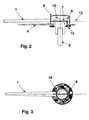
- FIGS. 2 and 3 show sectional representations of a pointer with permanent magnetic adjusting means for the pointer flag 1.
- a permanent magnet 14 which surrounds the pointer axis 2 in a ring is shown, which has at least two differently magnetized segments N and S. Shown are a segment with a magnetization as a magnetic north pole N and a segment with a magnetization as a magnetic south pole S.
- the pointer flag 1 pivots due to the existing between the actuating magnet 6 and the permanent magnet 14 magnetic forces by 180 ° about the axis 13 of their radial extent as soon as the actuating magnet 6 coming from a segment area N is moved over to the other segment area S.
- the pointer flag 1 remains in a certain defined angle of rotation with respect to the axis 13 of its radial extension due to the magnetic attraction forces.
- the pointer flag 1 can perform the function of a detector at that rotational angle position of the pointer axis 2, which is defined by the boundary surfaces of the two segment areas N and S, since the pointer flag 1 has two boundary surfaces which can be distinguished from one another in their appearance.
- the change in appearance can be caused by the fact that the top and bottom of the pointer flag 1 have different colors.
- This embodiment of the invention is of interest, for example, in connection with display devices designed as a tachometer if danger is to be signaled from a certain speed display or if a permissible operating range is to be signaled.
- the permanent magnetic actuators for the pointer flag 1 can also be realized purely mechanical solutions, if it is all about the pointer flag 1 at a certain angle of rotation the pointer axis 2 to rotate about the axis 13 of its radial extent.
- Such mechanical solutions can, for example, by a Gear arrangement and driver structures can be formed function like a roll counter.
- FIGS. 4 and 5 show sectional representations of a pointer with electromagnetic actuating means for the pointer flag 1.
- the pointer consists essentially of the same components as in the exemplary embodiment according to FIGS. 2 and 3. The only difference is that below the dial 4, instead of the permanent magnet 14, there is provided an energizable control coil 15 which surrounds the pointer axis 2 in an annular manner Actuating coil 15 is mounted in a pole guide ring 16 which guides the magnetic field generated by the energization in the direction of the two-pole actuating magnet 6 when the actuating coil 15 is energized.
- the adjusting coil 15 is connected to an electronic control circuit which, however, is not shown in FIGS. 4 and 5.
- the magnetic field between the actuating coil 15 and the actuating magnet 6 can be influenced, so that the pointer flag 1 can be rotated about the axis 13 of its radial extension by the magnetic forces acting on the actuating magnet 6 and can be held in a certain position.
- This rotary movement is independent of the rotation of the pointer flag 1 about the pointer axis 2.
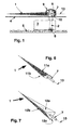
- FIGS. 6 and 7 exemplary embodiments for a pointer flag 1 are shown.
- 6 shows in perspective a pointer flag 1 with two opposing boundary surfaces 11a and 11b.
- FIG. 7 shows in perspective a pointer flag 1 with three boundary surfaces 12a, 12b and 12c, which in this example are arranged in such a way that the cross section of the body of the pointer flag 1 results in an equilateral triangle.
- the pointer flag 1 can, depending on the angle of rotation about the axis 13, of the boundary surfaces 11a, 11b or 12a, 12b and 12c emit different signal effects.
- FIGS. 8A, 8B, 8C and 8D show appearances of the pointer flag 1 at four different angles of rotation of the pointer axis 2.
- the pointer flag 1 moves clockwise over the dial 4, the pointer flag 1 being driven by the pointer axis 2, the pointer flag changes 1 at certain angular positions of the pointer axis 2, its appearance with respect to the boundary surface facing an observer, in this example the pointer flag 1 being designed with three boundary surfaces in accordance with FIG. 7.
- additional information can be reported to the viewer with the pointer flag 1 in addition to the conventional display function of the pointer flag 1 reliably and with a good signal effect.
- the formation of the pointer flag 1 with three boundary surfaces has the advantage that the viewer can also be provided with defined information, for example that a measurement parameter outside of a permissible operating range, through the transition regions in which two boundary surfaces are visible simultaneously as shown in FIG. 8C threatens to run.
- these figures show how a pointer flag 1, depending on its pointer position, conveys additional information to a viewer with good perceptibility quality.
- the pointer flag is about its radial axis Extension by means of a shaft mounted in the pointer axis turned that by a controllable energization of a around the pointer axis ring-shaped adjusting coil a magnetic Field between the control coil and one attached to the pointer flag Magnets trained and due to magnetic attraction or Repulsive forces defined the boundary surfaces of the pointer flag Take position so that a viewer of the display device very certain of these boundary surfaces is facing, whereby the Viewer through that assigned to this boundary surface Appearance of the pointer flag a certain message is conveyed.
- the magnetic field required to rotate the pointer flag is at precise execution of the adjusting coil and the pole guide ring, in which the Control coil is mounted, largely symmetrical.
- the pointer flag begins to rotate. Because with that from the magnetic field resulting torque must also the inevitable bearing friction Wave in the pointer axis can be overcome. On this issue Hardly anything changes when you assume that in practice the magnetic field due to manufacturing and arrangement tolerances be slightly distorted between the control coil and the control magnet like.
- At least one ferromagnetic auxiliary pole be provided through which is between the control coil and the control magnet forming magnetic field is deformed asymmetrically so that already relatively low forces from the magnetic field in of a certain equilibrium position of the positioning magnet in a Can move rotational movement.
- This through the ferromagnetic Auxiliary pole-induced field distortion therefore helps large impulse currents or to avoid excessive current in the control coil in order to avoid this Rotation of the pointer flag to generate the required starting torque.
- the auxiliary pole is arranged in relation to the control magnet that the permanent magnetic field of the control magnet with sufficient intensity can affect the auxiliary pole.
- a current surge in the control coil can cause a Torque can be exerted on the shaft of the pointer flag, so that this begins to rotate until it turns between magnetic field resulting attractive and repulsive forces Forms balance.
- the field of permanent magnetic poles of the Solenoid is primarily aligned to the pole guide ring, what about that leads to the control magnet becoming stable after every half turn Hold position swings.
- the energization of the control coil can accordingly be switched off as soon as the for the wave of the pointer flag Starting torque is applied.
- a in close proximity to the The auxiliary pole arranged in the solenoid is now reduced by that of him caused field distortion to generate the starting torque required electricity.
- This arrangement for a generic The display device thus has a favorable electrical energy balance.
- an auxiliary pole 20 was added to the arrangement shown in FIG. 9 .
- the auxiliary pole 20 consists of a ferromagnetic material and thus has a relative permeability ⁇ r > 1.
- the actuating magnet 6 and auxiliary pole 20 are arranged in such a way that the permanent magnetic field of the actuating magnet 6 can extend to the ferromagnetic auxiliary pole 20 with a sufficient magnetic field strength.
- FIG. 10 shows in a sectional plane AA a pointer with an actuating magnet 6 and an auxiliary pole 20 designed as a pin 21 or rod, the auxiliary pole 20 being positioned in such a way that it is spaced approximately the same distance from the actuating magnet 6 and from the pole guide ring 16. The distance lies approximately between the single to double dimension of the diameter of the pin 21.
- the position of the cutting plane AA can also be seen in connection with the previously explained FIGS. 4 and 9.
- FIG. 11 shows in section plane AA a pointer with an actuating magnet 6 and an auxiliary pole 20 designed as a clip 22.
- This clip 22 can be manufactured as a stamped and bent part from a ferromagnetic material and locked in the pointer cap 9 or above the prism head 10 or there be glued.
- this clip 22 is shown as a single part as a bracket made of a ferromagnetic material.
- a further embodiment of the auxiliary pole 20 can also consist in the fact that the pointer cap 9 is doped with metal fibers made of a ferromagnetic material and is shaped correspondingly towards the actuating magnet 6, so that the auxiliary pole 20 becomes an integral part of the pointer cap 9.
- the pointer cap 9 could also be designed as a ferromagnetic deep-drawn part with a suitable geometry.
- FIG. 13 shows a longitudinal and a rear view of an auxiliary pole 20 designed as a pin 21 or rod.
Landscapes
- Physics & Mathematics (AREA)
- General Physics & Mathematics (AREA)
- Details Of Measuring Devices (AREA)
- Indicating Measured Values (AREA)
- Devices For Indicating Variable Information By Combining Individual Elements (AREA)
- Details Of Measuring And Other Instruments (AREA)
Applications Claiming Priority (4)
| Application Number | Priority Date | Filing Date | Title |
|---|---|---|---|
| DE10008211 | 2000-02-23 | ||
| DE2000108211 DE10008211A1 (de) | 2000-09-06 | 2000-02-23 | Anzeigevorrichtung mit einem Zeiger |
| DE10043950A DE10043950A1 (de) | 2000-02-23 | 2000-09-06 | Anzeigevorrichtung mit einem Zeiger |
| DE10043950 | 2000-09-06 |
Publications (2)
| Publication Number | Publication Date |
|---|---|
| EP1128166A2 true EP1128166A2 (fr) | 2001-08-29 |
| EP1128166A3 EP1128166A3 (fr) | 2002-01-09 |
Family
ID=26004475
Family Applications (1)
| Application Number | Title | Priority Date | Filing Date |
|---|---|---|---|
| EP01103912A Withdrawn EP1128166A3 (fr) | 2000-02-23 | 2001-02-17 | Indicateur comportant une aiguille |
Country Status (4)
| Country | Link |
|---|---|
| US (1) | US6470822B2 (fr) |
| EP (1) | EP1128166A3 (fr) |
| BR (1) | BR0100472A (fr) |
| DE (1) | DE10043950A1 (fr) |
Families Citing this family (21)
| Publication number | Priority date | Publication date | Assignee | Title |
|---|---|---|---|---|
| AUPQ592700A0 (en) * | 2000-02-29 | 2000-03-23 | Australian Arrow Pty Ltd | Instrument reference system |
| DE10063875A1 (de) * | 2000-12-21 | 2002-07-04 | Siemens Ag | Anzeigeinstrument |
| US6827034B1 (en) * | 2002-09-25 | 2004-12-07 | Yazaki North America, Inc. | Illuminated dial and pointer display |
| US6974220B2 (en) * | 2002-12-12 | 2005-12-13 | Siemens Vdo Automotive Corporation | Bright pointer for instrument cluster |
| JP4213487B2 (ja) * | 2003-02-18 | 2009-01-21 | カルソニックカンセイ株式会社 | 計器用指針組付構造および組付方法 |
| FR2880420B1 (fr) * | 2005-01-05 | 2007-02-23 | Johnson Controls Tech Co | Aiguille a bord contraste pour compteur ou similaire, et procede de fabrication d'une telle aiguille |
| JP2006301241A (ja) * | 2005-04-20 | 2006-11-02 | Roland Corp | 調律装置 |
| US7575331B2 (en) | 2005-12-15 | 2009-08-18 | Continental Automotive Systems Us, Inc. | Compensation free illumination of instrument cluster display |
| FR2901605B1 (fr) * | 2006-05-24 | 2008-08-08 | Sonceboz Sa Suisse | Module indicateur de tableau de bord |
| JP5007936B2 (ja) * | 2007-04-11 | 2012-08-22 | 日本精機株式会社 | 指示計器装置 |
| JP2009162713A (ja) * | 2008-01-10 | 2009-07-23 | Nippon Seiki Co Ltd | 指示計器装置 |
| FR2929702B1 (fr) * | 2008-04-08 | 2015-05-22 | Johnson Controls Tech Co | Dispositif d'affichage, notamment pour vehicule automobile, et procede de montagne d'une aiguille pour un dispositif d'affichage |
| WO2009124712A2 (fr) * | 2008-04-08 | 2009-10-15 | Johnson Controls Technology Company | Dispositif indicateur et dispositif d'affichage, notamment pour vehicule automobile, et procede de montage d'une aiguille pour un dispositif d'affichage |
| RU2010133346A (ru) * | 2010-08-09 | 2012-02-20 | Общество с ограниченной ответственностью "Секунда" (RU) | Способ визуального представления информации о показаниях приборов со стрелочной индикацией |
| US8336407B2 (en) * | 2011-03-08 | 2012-12-25 | Landis+Gyr Innovations, Inc. | Utility meter adapter |
| US8656789B2 (en) | 2011-03-08 | 2014-02-25 | Landis+Gyr Innovations, Inc. | Adapter assembly for a utility meter for wirelessly transmitting data |
| US8451001B2 (en) | 2011-08-09 | 2013-05-28 | Landis+Gyr Innovations, Inc. | Utility meter adapter |
| KR101518916B1 (ko) * | 2013-12-18 | 2015-05-11 | 현대자동차 주식회사 | 차량용 클러스터 포인터 조명장치 |
| US9404774B2 (en) * | 2014-09-15 | 2016-08-02 | Delphi Technologies, Inc. | Instrument panel assembly with variable length pointer |
| US9581471B2 (en) * | 2014-12-30 | 2017-02-28 | Continental Automotive Systems, Inc. | Gauge with multiple color pointer tip |
| WO2024069259A1 (fr) * | 2022-09-27 | 2024-04-04 | Deo Bhanu Kumar | Dispositif permettant d'indiquer des informations et d'influencer des événements |
Family Cites Families (6)
| Publication number | Priority date | Publication date | Assignee | Title |
|---|---|---|---|---|
| US3776176A (en) * | 1972-03-15 | 1973-12-04 | Master Electronics Corp | Indicator device which can be illuminated |
| DE3330736A1 (de) * | 1983-08-26 | 1985-03-07 | Qualitrol Gmbh, 6222 Geisenheim | Zeigerachsenverstellvorrichtung |
| US5050045A (en) * | 1990-10-01 | 1991-09-17 | Nippondenso Co., Ltd. | Self-luminescent pointer device for a gauge |
| FR2699273B1 (fr) * | 1992-12-11 | 1995-03-03 | Jaeger | Dispositif indicateur à aiguille perfectionné. |
| JP3470829B2 (ja) * | 1994-09-26 | 2003-11-25 | 矢崎総業株式会社 | 計器用指針 |
| US5797345A (en) * | 1996-11-13 | 1998-08-25 | Ford Global Technologies, Inc. | Illuminated pointer for instrument gage |
-
2000
- 2000-09-06 DE DE10043950A patent/DE10043950A1/de not_active Ceased
-
2001
- 2001-02-09 BR BR0100472-7A patent/BR0100472A/pt not_active Application Discontinuation
- 2001-02-17 EP EP01103912A patent/EP1128166A3/fr not_active Withdrawn
- 2001-02-22 US US09/789,423 patent/US6470822B2/en not_active Expired - Fee Related
Also Published As
| Publication number | Publication date |
|---|---|
| BR0100472A (pt) | 2001-10-30 |
| EP1128166A3 (fr) | 2002-01-09 |
| US6470822B2 (en) | 2002-10-29 |
| US20020059895A1 (en) | 2002-05-23 |
| DE10043950A1 (de) | 2002-03-21 |
Similar Documents
| Publication | Publication Date | Title |
|---|---|---|
| EP1128166A2 (fr) | Indicateur comportant une aiguille | |
| DE69224639T2 (de) | Gerät zur instrumentenanzeige in einem pkw | |
| EP0920604A1 (fr) | Dispositif de detection sans contact d'un angle de rotation ou d'un mouvement lineaire | |
| DE19537666A1 (de) | Zeigerinstrument | |
| EP0981457A1 (fr) | Dispositif d'entrainement pour un element, pouvant se deplacer entre des positions finales, d'un vehicule et son procede de production | |
| DE1524616C3 (de) | Anzeigevorrichtung | |
| DE2747794A1 (de) | Anzeigeeinheit | |
| WO1999030112A1 (fr) | Dispositif de mesure pour determiner sans contact un angle de rotation | |
| DE1512730A1 (de) | Elektromagnetische Miniaturanzeigevorrichtung | |
| DE4311496C2 (de) | Handbetätigter Winkelgeber | |
| DE10008211A1 (de) | Anzeigevorrichtung mit einem Zeiger | |
| DE19627089C1 (de) | Handbetätigter Winkelgeber | |
| DE19852915A1 (de) | Meßvorrichtung zur berührungslosen Erfassung eines Drehwinkels | |
| DE19753775A1 (de) | Meßvorrichtung zur berührungslosen Erfassung eines Drehwinkels | |
| WO1999030113A1 (fr) | Dispositif de mesure pour determiner sans contact un angle de rotation | |
| DE2146659C3 (de) | Bistabiler elektromagnetischer Anzeiger | |
| DE2927958C2 (fr) | ||
| DE1935678A1 (de) | Vorrichtung zur visuellen Darstellung von Zei?h? mittels eines mosaikartigen Systems elektromagnetisch gesteuerter Anzeigeorgane | |
| DE744875C (de) | Vorrichtung zur Kontrolle einer Anzahl elektrischer Lampen und sonstiger elektrischer Apparate eines Kraftfahrzeuges | |
| DE4020275C2 (de) | Stellenantrieb zur Einstellung von zwei selbsthaltenden Lagen | |
| EP1182430B1 (fr) | Indicateur comportant une aiguille | |
| DE3403073C2 (de) | Fernsteuerbare elektromagnetische alphanumerische Anzeigevorrichtung | |
| EP1625361B1 (fr) | Commande incrementale | |
| DE4308660A1 (de) | Hysterese-Kupplung | |
| EP0847570A1 (fr) | Indicateur d'etat de fonctionnement |
Legal Events
| Date | Code | Title | Description |
|---|---|---|---|
| PUAI | Public reference made under article 153(3) epc to a published international application that has entered the european phase |
Free format text: ORIGINAL CODE: 0009012 |
|
| AK | Designated contracting states |
Kind code of ref document: A2 Designated state(s): AT BE CH CY DE DK ES FI FR GB GR IE IT LI LU MC NL PT SE TR |
|
| AX | Request for extension of the european patent |
Free format text: AL;LT;LV;MK;RO;SI |
|
| PUAL | Search report despatched |
Free format text: ORIGINAL CODE: 0009013 |
|
| AK | Designated contracting states |
Kind code of ref document: A3 Designated state(s): AT BE CH CY DE DK ES FI FR GB GR IE IT LI LU MC NL PT SE TR |
|
| AX | Request for extension of the european patent |
Free format text: AL;LT;LV;MK;RO;SI |
|
| RAP1 | Party data changed (applicant data changed or rights of an application transferred) |
Owner name: SIEMENS AKTIENGESELLSCHAFT |
|
| AKX | Designation fees paid | ||
| 17P | Request for examination filed |
Effective date: 20020827 |
|
| RBV | Designated contracting states (corrected) |
Designated state(s): AT BE CH CY DE DK ES FI FR GB GR IE IT LI LU MC NL PT SE TR |
|
| REG | Reference to a national code |
Ref country code: DE Ref legal event code: 8566 |
|
| 17Q | First examination report despatched |
Effective date: 20070612 |
|
| STAA | Information on the status of an ep patent application or granted ep patent |
Free format text: STATUS: THE APPLICATION IS DEEMED TO BE WITHDRAWN |
|
| 18D | Application deemed to be withdrawn |
Effective date: 20071228 |