EP1128189B1 - Verfahren, Instrument und System zur Durchführung von Kontrollmessungen und Korrekturen von magnetischen Feldern in Magneten von MRI-Maschinen - Google Patents
Verfahren, Instrument und System zur Durchführung von Kontrollmessungen und Korrekturen von magnetischen Feldern in Magneten von MRI-Maschinen Download PDFInfo
- Publication number
- EP1128189B1 EP1128189B1 EP01104142A EP01104142A EP1128189B1 EP 1128189 B1 EP1128189 B1 EP 1128189B1 EP 01104142 A EP01104142 A EP 01104142A EP 01104142 A EP01104142 A EP 01104142A EP 1128189 B1 EP1128189 B1 EP 1128189B1
- Authority
- EP
- European Patent Office
- Prior art keywords
- image
- coefficients
- field
- baffles
- magnetic resonance
- Prior art date
- Legal status (The legal status is an assumption and is not a legal conclusion. Google has not performed a legal analysis and makes no representation as to the accuracy of the status listed.)
- Expired - Lifetime
Links
- 230000005291 magnetic effect Effects 0.000 title claims abstract description 76
- 238000000034 method Methods 0.000 title claims abstract description 43
- 238000012937 correction Methods 0.000 title claims abstract description 32
- 238000005259 measurement Methods 0.000 title claims abstract description 14
- 238000012795 verification Methods 0.000 title claims abstract description 13
- 238000013421 nuclear magnetic resonance imaging Methods 0.000 title claims abstract description 11
- 238000012360 testing method Methods 0.000 claims abstract description 58
- 238000005481 NMR spectroscopy Methods 0.000 claims abstract description 21
- 230000006870 function Effects 0.000 claims description 17
- 230000003068 static effect Effects 0.000 claims description 12
- 239000000463 material Substances 0.000 claims description 8
- 238000012545 processing Methods 0.000 claims description 8
- 238000003384 imaging method Methods 0.000 claims description 6
- 229920005372 Plexiglas® Polymers 0.000 claims description 5
- 239000003302 ferromagnetic material Substances 0.000 claims description 5
- 239000004926 polymethyl methacrylate Substances 0.000 claims description 5
- 238000002592 echocardiography Methods 0.000 claims description 4
- 239000007788 liquid Substances 0.000 claims description 4
- 239000004033 plastic Substances 0.000 claims description 4
- 229920003023 plastic Polymers 0.000 claims description 4
- 230000005294 ferromagnetic effect Effects 0.000 claims description 3
- XLYOFNOQVPJJNP-UHFFFAOYSA-N water Substances O XLYOFNOQVPJJNP-UHFFFAOYSA-N 0.000 claims description 3
- GNFTZDOKVXKIBK-UHFFFAOYSA-N 3-(2-methoxyethoxy)benzohydrazide Chemical compound COCCOC1=CC=CC(C(=O)NN)=C1 GNFTZDOKVXKIBK-UHFFFAOYSA-N 0.000 claims description 2
- 238000001514 detection method Methods 0.000 claims description 2
- 238000007620 mathematical function Methods 0.000 claims description 2
- 230000002093 peripheral effect Effects 0.000 claims description 2
- 239000000126 substance Substances 0.000 claims 1
- 230000004075 alteration Effects 0.000 description 9
- 238000010276 construction Methods 0.000 description 8
- 230000000875 corresponding effect Effects 0.000 description 6
- 238000009434 installation Methods 0.000 description 3
- 238000004519 manufacturing process Methods 0.000 description 3
- 230000008569 process Effects 0.000 description 3
- 101500027295 Homo sapiens Sperm histone HP3 Proteins 0.000 description 2
- 102400000926 Sperm histone HP3 Human genes 0.000 description 2
- 238000004364 calculation method Methods 0.000 description 2
- 230000000694 effects Effects 0.000 description 2
- 238000005070 sampling Methods 0.000 description 2
- 238000000264 spin echo pulse sequence Methods 0.000 description 2
- 101500027298 Homo sapiens Sperm histone HP2 Proteins 0.000 description 1
- 102400000927 Sperm histone HP2 Human genes 0.000 description 1
- 239000002131 composite material Substances 0.000 description 1
- 230000002596 correlated effect Effects 0.000 description 1
- 239000000945 filler Substances 0.000 description 1
- 230000006698 induction Effects 0.000 description 1
- 238000012423 maintenance Methods 0.000 description 1
- 239000002184 metal Substances 0.000 description 1
- 230000000284 resting effect Effects 0.000 description 1
- 239000000523 sample Substances 0.000 description 1
- 238000007789 sealing Methods 0.000 description 1
- 230000000007 visual effect Effects 0.000 description 1
Images


Classifications
-
- G—PHYSICS
- G01—MEASURING; TESTING
- G01R—MEASURING ELECTRIC VARIABLES; MEASURING MAGNETIC VARIABLES
- G01R33/00—Arrangements or instruments for measuring magnetic variables
- G01R33/20—Arrangements or instruments for measuring magnetic variables involving magnetic resonance
- G01R33/44—Arrangements or instruments for measuring magnetic variables involving magnetic resonance using nuclear magnetic resonance [NMR]
- G01R33/48—NMR imaging systems
- G01R33/54—Signal processing systems, e.g. using pulse sequences ; Generation or control of pulse sequences; Operator console
- G01R33/56—Image enhancement or correction, e.g. subtraction or averaging techniques, e.g. improvement of signal-to-noise ratio and resolution
- G01R33/565—Correction of image distortions, e.g. due to magnetic field inhomogeneities
- G01R33/56563—Correction of image distortions, e.g. due to magnetic field inhomogeneities caused by a distortion of the main magnetic field B0, e.g. temporal variation of the magnitude or spatial inhomogeneity of B0
-
- G—PHYSICS
- G01—MEASURING; TESTING
- G01R—MEASURING ELECTRIC VARIABLES; MEASURING MAGNETIC VARIABLES
- G01R33/00—Arrangements or instruments for measuring magnetic variables
- G01R33/20—Arrangements or instruments for measuring magnetic variables involving magnetic resonance
- G01R33/44—Arrangements or instruments for measuring magnetic variables involving magnetic resonance using nuclear magnetic resonance [NMR]
- G01R33/48—NMR imaging systems
- G01R33/58—Calibration of imaging systems, e.g. using test probes, Phantoms; Calibration objects or fiducial markers such as active or passive RF coils surrounding an MR active material
Definitions
- the invention is directed to a method for performing verification measurements and corrections of magnetic fields in magnets for Nuclear Magnetic Resonance imaging machines, comprising the following steps:
- Nuclear Magnetic Resonance imaging machines use electromagnetic echoes of previously excited nuclei to retrieve therefrom information for imaging.
- echo signals allowing to reconstruct images sufficiently corresponding to reality, at least a considerable number of the nuclei of the material being examined must be oriented with substantially parallel spins.
- static magnetic fields are used which must be comparatively intense and constant within a predetermined volume corresponding to a body part to be examined.
- gradients which are used to select certain sections of the body part to be examined and to create a parameter for identifying the signal received from individual portions of the section under examination so that signals can be ordered for two- or three-dimensional imaging.
- magnets are submitted to fine calibration of the magnetic field, the so-called shimming, which is designed to correct construction inaccuracies of the individual parts of the magnet, and includes measuring the static field by a probe, detecting aberrations with respect to nominal values and disposing magnetized or ferromagnetic correcting elements in several appropriate areas of the magnet structure as determined from the differences between the nominal values and the actual values of the field within the volume designed to accommodate the body or the body part under examination. Shimming is performed during fabrication at the manufacturer's site.
- manufacture settings appear to be changed or perturbed. This is especially caused by stresses acting on the big metal masses which form the magnetic structure, especially as this structure has a modular construction, or is made of several parts fastened together.
- the invention has the main object to allow fast functional testing of the magnetic structure of Nuclear Magnetic Resonance machines, particularly after installation, in a relatively fast and simple manner.
- the invention has the further object to allow an at least partly automatic correction of aberrations and anomalies occurring after installation without requiring special laboratory equipment, which is complex and costly and may be only used by very highly knowledgeable and specialized personnel.
- the invention also aims at setting the bases for implementation of several automation degrees of the correction to be performed, with the smallest number of operation steps which might be carried out by an average specialized technician, specifically trained in the maintenance of one or more specific machines.
- the invention achieves the above purposes with a method for performing verification measurements and corrections of magnetic fields in magnets for Nuclear Magnetic Resonance imaging machines, in which
- a mathematical theoretical function describing the field is choosen, particularly a polynomial expansion, preferably a spherical polynomial expansion,
- a phantom is provided with a structure suited to the said function describing the filed and which produces one or more selected images, each of these images being correlated to one or to a limited number of selected low order coefficients of the function describing the filed, such that the differences between a theoretical image of the phantom and the real image of the phantom depends only on the one or on the limited number of selected coefficients of the function describing the magnetic field.
- the above method may be refined so that several orders and degrees of harmonics, and hence of field coefficients may be examined individually.
- the method provides that the test member has elements which do not emit Nuclear Magnetic Resonance signals (and are defined "transparent" in the following text and claims), which are related to a definite harmonic or to precise coefficients of a certain order of a mathematical description of the field by a polynomial expansion, preferably by spherical harmonics, there being provided means for application of reading gradients of the magnetic field, which only detect the echo signal along certain directions, said directions being selected in such a manner as to suppress the contributions from the magnetic field described by coefficients other than the ones being examined.
- the describing polynomial expansion is selected in spherical harmonics. Nevertheless, other polynomial expansions may be more or less suitable for the purpose, also depending on the symmetries of the field and hence of the magnetic structure.
- the latter includes the following steps:
- steps a) to f) may be repeated to verify the effectiveness of said correction and, when necessary, an additional correction step g) may be performed.
- the elements for verifying the different coefficients may be progressively mounted on the test member or fixedly provided thereon.
- Each of these elements corresponds to at least one harmonic or to at least one set of coefficients and are made consistently with the selected mathematical description of the field and/or eventually to the symmetries of the magnetic structure.
- the method provides a manual graphic comparison between the detected images and the theoretical images wherefrom the mathematical computation is performed to determine correction data.
- the machine will have a theoretical comparison image, for instance stored therein.
- the method provides that the machine determines quantitatively the differences between the ideal image and the detected image by computation of the distance in pixels of the point or portion or area of the detected image from the position of the corresponding point or area of the ideal image.
- the difference may be easily changed to an aberration or deviation quantitative value with respect to the theoretical image and directly used in the machine thanks to the processing hardware contained therein and to software for effecting comparisons, tests and error diagnostics.
- computation software also stored in the processing hardware of the machine may compute the required corrections and indicate correction absolute data.
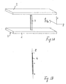
- the method provides the use of a test element whose non-detectable portion has the form of a rib, stem or baffle whose longitudinal orientation is parallel to the static magnetic field, i.e. disposed in the axial section plane of the magnetic field when the latter is described with spherical harmonics.
- this stem is related to (2 0) and (4 0) cosine coefficients.
- (x y) typically defines the indexes of the polynomial expansion.
- the invention is also directed to a test element including, separately or in combination, the above baffles.
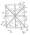
- such test element includes a central rectilinear baffle which is crossed, with reference to the plane parallel to a peripheral edge, by two crossed baffles, passing through the median area of the rectilinear baffle and forming, symmetrically with respect to the rectilinear baffle, an angle of 109.472°, whereas two additional crossed baffles are provided in the plane perpendicular to the rectilinear baffle and containing the other sides thereof, which form, symmetrically with respect to said rectilinear baffle, an angle of 90° and intersect the rectilinear baffle in the central area.
- the baffles consist of walls and are made of plastic, particularly of the so-called Plexiglas.
- the different baffles made of a material which emits no Nuclear Magnetic Resonance signal are mounted in a fixed manner inside a plastic container filled with a liquid which emits a Nuclear Magnetic Resonance signal, e.g. water or other liquids or solutions.
- the box or container have a filler opening with sealing means.
- the advantages of the present invention are apparent from the above disclosure. Thanks to the verification and correction method, the homogeneity accuracy of the magnetic field may be periodically controlled in an easy manner, manually and/or with different automation degrees. This feature is primarily important for obtaining Nuclear Magnetic Resonance images with a good correspondence with reality, hence it is the basis to obtain diagnostically usable images.
- Verification and, when needed, correction activities may be automated to such an extent that they may be performed by an average specialized operator, without requiring any intervention of highly specialized personnel, which involve high costs both for the manufacturer and for the customer.
- the required process and devices are relatively inexpensive, mainly involving the addition of software procedures in existing machine elements, which only need to be enhanced, and the provision of a set of correction permanent magnets, as well as of a phantom.
- the latter is the only construction element which has to be specially fabricated for an easy application of the method.
- the phantom itself is in no way necessary, the verification and correction procedures being performable, by following the above method steps, with hand-made elements or improvised members.
- Figs. 1A and 1B to 4A and 4B show schematically by a tridimensional view and a plan view on the specific extension plane, the test elements for verification of specific field coefficients according to a spherical polynomial expansion.
- Fig. 5 shows a flow chart of the method according to the invention.
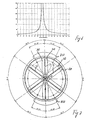
- Fig. 6 shows the ratio of two coefficients as a function of the angle formed by the test baffle in the specific plane.
- Figs. 7 and 8 are two views along two axes, of the composite test element according to a preferred embodiment of the invention.
- the method of the invention provides Nuclear Magnetic Resonance imaging of a test element and comparison of the deviations of said real detected image with a nominal, ideal image of the test element.
- the process is shown with reference to the test element example of figs. 1A and 1B.
- I denotes the ideal image and I' the actually detected image of the test element 1, according to figs. 1A and 1B.
- I+I' denotes the comparison between the two images. This is obtained by superposing the two images I, I'.
- verification might as well be carried out visually, and aberrations be detected by manual measurement on the monitor. However, depending on the desired automation degree, such graphically represented verification may be obtained automatically by pure computation, whereas the visual image may only be a graphic representation of the information obtained from computations.
- aberration values i.e. substantially the differences between points P1 and P1' to Pn and Pn' are used for computing the corrections to be applied to the magnetic structure 1.
- Such corrections are provided in the form of magnetic elements M1, M2, Mn, having a unit value or being a fraction or a multiple of said unit value, or in the form of one or more elements with a predetermined volume of ferromagnetic material, which have to be positioned at predetermined locations of the magnetic structure to correct any aberration of the magnetic field, here of the static magnetic field denoted by Bz in the figures.
- the magnetic field is described with the help of a polynomial expansion in spherical harmonics which relate coefficients of different orders to combinations of sine and cosine functions.
- This description allows to produce test elements whose image contributions only relate to defined coefficients describing the magnetic field in spherical harmonics and have very simple geometries and constructions for this purpose.
- test element of figs. 1A and 1B allows separate detection of (2 0) cosine and of (4 0) cosine coefficients.
- the test element consists of a rectilinear baffle 4, which is positioned in the plane parallel to the magnetic field Bz, obviously between the two poles 2, 3 for generating the magnetic field.
- the rectilinear baffle is oriented along the Z axis.
- the tesseral coefficients with a non-zero degree give a null contribution on the axes.
- I in fig. 1 The ideal image which should be obtained is denoted by I in fig. 1. If the field is inhomogeneous, the actual image might be the one denoted by I' in fig. 5.
- the desired coefficients are obtained, i.e. (2 0) cosine and (4 0) cosine coefficients.
- Fig. 6 shows a chart of the (2 2) to (2 0) coefficients ratio as a function of the angular position of the baffles 5 and 5'. The peak apparently corresponds to the angle of 54.736°.
- baffles are positioned, as in the example of figs. 2A and 2B, in the XY plane, i.e. in the coronal section plane, but they are disposed along the bisectors of the cartesian coordinates XY.
- the (2 1) cosine coefficient is measured substantially as described above.
- baffles 7, 7' like those 6, 6' of figs. 3A and 3B, even as regards angular arrangement are positioned in the sagittal section plane, i.e. in the XZ plane, as shown in figs. 4A and 4B.
- the operations are the same, and the following law for describing the distortion curve is obtained:
- the operations for computing and determining distortions may be performed outside the machine, or the software for automatically determining correction magnetic charges and their position from the comparison of data detected in the measuring session with stored nominal data, in relation to the different test elements 4, 5, 6, 7, as shown in the schematic flow chart of fig. 5, may be loaded in the Nuclear Magnetic Resonance machine.
- Figs. 7 and 8 show a preferred embodiment of a test element for performing the measurement and correction procedures indicated and detailed herebefore.
- This test element has all the individual elements 4, 5, 5', 6, 6', 7, 7' permanently therein. These may be mounted in a fixed manner in the test element, but may be also possibly removable or a set of individual test elements may be provided, each with the baffles in one of the configurations described in figs. 1, 2, 3, 4.
- the test element 10 consists of a cylindrical Plexiglas container 1, wherein the baffles 4, 5, 5', 6, 6' and 7, 7'.
- the baffles 6, 7 and 6', 7' are identical, with the test element, resting on the circular base, only having to be rotated through 90°.
- 7, 6 and 7', 6' there may be also provided a set of baffles in a plane perpendicular to the one containing the first baffles 6, 7 and 6', 7', so that the test element does not have to be moved or oriented several times, and that a single first positioning may be needed to perform any further measurement.
- the baffles 4, 5, 6, 7, 5', 6', 7' extend along axes which form angles indicated with reference to figs. 1, 2, 3, 4, all intersecting in the origin 0, which is provided in coincidence with the median point of the cylindrical test element 10.
- the baffles 4, 5, 6, 7, 5', 6', 7' consist of thin diaphragms or ribs separating apertures 110 formed in a plexiglas disk mounted inside the test element 10.
- baffles 6, 7, 6', 7' are formed in diametral walls of the test element, in a single diametral wall if the test element is to be rotated for performing different measurements, or in two perpendicular diametral walls.
- the two walls are denoted by 210 and 210' in fig. 8.
- the baffles consist of thin ribs separating apertures 310, 410.
- an opening is provided which may be sealed by a plug 11, whereby the cylindrical sealed container-like test element is filled with a liquid which generates Nuclear Magnetic Resonance signals, e.g. simple water , and which completely fills the test element, including the different apertures 110, 310, 410 which define the baffles 4, 5, 5', 6, 6', 7, 7'.
- a liquid which generates Nuclear Magnetic Resonance signals e.g. simple water
- the test member Upon measuring, the test member is inserted inside the receiving coil of a Nuclear Magnetic Resonance imaging machine in such a position that the axis of the cylindrical member is oriented perpendicular to the static magnetic field indicated by the arrow Bz in fig. 8.
- the member is positioned with the baffles, i.e. walls 210, oriented parallel to the two cartesian axes which define the planes perpendicular to the direction of the static magnetic field, i.e. the faces of the two opposite poles 2, 3, whereas the baffle 4 is oriented along the y axis of said plane, i.e. according to one of the reading gradients.
- the member has extensions 510, 610, 710 for easy positioning and grasping thereof.
- the member as shown in figs. 7 and 8 is particularly suitable for measurement of field coefficients as described hereinbefore with reference to the method and to figs. 1 to 5.
- a Nuclear Magnetic Resonance imaging machine which has at least one magnetic structure for generating static magnetic fields with a predetermined orientation; electronic means and coils for generating spin echo sequences, as well as selecting, reading and encoding gradients; coils for receiving echoes and an electronic signal processing unit, said electronic unit being programmed for performing at least some of the steps of the method described hereinbefore, and there being provided, in combination therewith, at least one set of correcting magnetic charges, whose values are fractions or multiples of magnetic charge units.
Landscapes
- Physics & Mathematics (AREA)
- Health & Medical Sciences (AREA)
- General Health & Medical Sciences (AREA)
- Nuclear Medicine, Radiotherapy & Molecular Imaging (AREA)
- Radiology & Medical Imaging (AREA)
- Engineering & Computer Science (AREA)
- Signal Processing (AREA)
- High Energy & Nuclear Physics (AREA)
- Condensed Matter Physics & Semiconductors (AREA)
- General Physics & Mathematics (AREA)
- Magnetic Resonance Imaging Apparatus (AREA)
- Measuring Magnetic Variables (AREA)
Claims (23)
- Verfahren zur Durchführung von Kontrollmessungen und Korrekturen an magnetischen Feldern von Magneten in bilderzeugenden, auf dem Prinzip der Kernmagnetresonanz (NMR) beruhenden Geräten, das folgende Schritte enthält:gekennzeichnet durch folgende weitere Schritte:Herstellung eines Prüfstücks (10; 4, 5, 5, 6, 6', 7, 7'), dessen Eigenschaften derart sind, dass sich vordefinierte und bekannte NMR-Bilder (I) erzeugen lassen, und Erfassung eines NMR-Bildes von besagtem Phantom (Ii);Vergleich des bekannten Soll-Bildes mit dem ermittelten Bild (I+I') und/oder der erhaltenen Signale, mit deren Hilfe das ermittelte Bild dargestellt wurde, mit den entsprechenden, dem bekannten Soll-Bild zuzuordnenden Signalen für alle sich auf sie beziehenden Verarbeitungs- oder Bilderzeugungsschritte;Ermittlung der Differenzen zwischen ermitteltem Bild und bekanntem Bild (I+I', IS) oder zwischen den ermittelten Signalen und den jeweiligen, dem bekannten Bild zuzuordnenden Signalen;Gestützt auf besagte Differenzen die Berechnung von Korrekturparametern, d.h. der magnetischen Korrekturladung (M1, M2, ..., Mn) und/oder der Anzahl der magnetischen Korrekturladungen, die über einen jeweils vordefinierten Wert verfügen, oder der Menge des ferromagnetischen Materials und/oder der Anzahl der ferromagnetischen Korrekturelemente, die über ein jeweils vordefiniertes Volumen verfügen, sowie die Positionierung besagter Korrekturelemente innerhalb der Magnetbaugruppe,Wahl einer mathematischen Funktion zur Beschreibung des Feldes, vorzugsweise einer polynomialen Entwicklung;Einsatz eines Phantoms als Prüfstück, dessen Struktur sich für besagte Feldbeschreibungsfunktion eignet und das Beiträge zur Bilderzeugung auf eine Weise liefert, bei der jeder dieser Beiträge zur Bilderzeugung sich auf einen oder aber eine gewisse Zahl ausgewählter Koeffizienten niedriger Ordnung der Feldbeschreibungsfunktion bezieht, so dass die Differenzen zwischen dem Soll-Bild und dem tatsächlichen Bild des Phantoms nur von einem oder aber einer gewissen Zahl ausgewählter Koeffizienten der Funktion zur Beschreibung des magnetischen Feldes abhängen.
- Verfahren nach Anspruch 1, gekennzeichnet dadurch, dass für die definierte mathematische Struktur zur Feldbeschreibung als Felddarstellung die Kugelfunktionsmethode gewählt wird, wobei nur unterschiedliche Ordnungen und Grade der Oberschwingungen und folglich auch der Feldkoeffizienten unabhängig voneinander untersucht werden können.
- Verfahren nach Anspruch 1 oder 2, gekennzeichnet dadurch, dass das Prüfstück (10) über Prüfelemente (4, 5, 5', 6, 6', 7, 7') verfügt, die keine NMR-Signale aussenden, so dass sich der durch ein einzelnes Prüfelement erzeugte Beitrag zur Bilderzeugung auf eine bestimmte Oberschwingung oder auf definierte Koeffizienten bestimmter niedriger Ordnung einer mathematischen Feldbeschreibung, die einer polynomialen Entwicklung, vorzugsweise nach der Kugelfunktionsmethode, bezieht und auf diese Weise die Möglichkeit schafft, Lesegradienten des Magnetfeldes zu erzeugen, die Echosignale nur entlang bestimmter Richtungen erfassen, wobei besagte Richtungen so gewählt werden können, dass Beiträge aus dem Magnetfeld, die durch andere Koeffizienten als die untersuchten beschrieben werden, unterdrückt und auf diese Weise die Beiträge der untersuchten Koeffizienten von denen der restlichen Koeffizienten getrennt erfasst werden können.
- Verfahren nach einem oder mehreren der vorhergehenden Ansprüche, gekennzeichnet dadurch, dass für die beschreibende polynomiale Entwicklung die Kugelfunktionsmethode gewählt wird.
- Verfahren nach einem oder mehreren der vorhergehenden Ansprüche, gekennzeichnet durch folgende Schritte:a) Erfassung des Bildes (I') des vordefinierten Prüfelementes (10, 4);b) Symmetrisierung der Abweichungen zwischen tatsächlich erfasstem Bild (I') und idealem Soll-Bild (I) hinsichtlich Bildmitte und/oder vordefiniertem Ursprung des Koordinatensystems für die mathematische Beschreibung des Magnetfeldes;c) Definition einer Kurve der symmetrisierten Abweichungen mit den jeweiligen Feldkoeffizienten als Variable;d) Ermittlung eines Polynoms zur näherungsweisen Beschreibung der Kurve der symmetrisierten Abweichungen, abgeleitet aus den Differenzen zwischen tatsächlichem Bild (I') und idealem Soll-Bild (I);e) Ermittlung der Koeffizienten auf der Grundlage des Systems zweier konsistenter Gleichungen aus Schritt c) undf) unter Zugrundelegung der mathematischen Feldbeschreibung nach der Kugelfunktionsmethode Berechnung der Korrekturelemente hinsichtlich von Anzahl, Größe und Position innerhalb der Magnetbaugruppe (1) in Form von magnetischen Ladungen oder der Menge des ferromagnetischen Materials (M1, M2, ..., Mn) mit dem Ziel, die gemessenen Werte der Feldkoeffizienten auf ihre für die Erfassung nutzbarer NMR-Bilder Homogenitätseigenschaften des Feldes erforderlichen und im Einklang mit den Homogenitätsmerkmalen stehenden Sollwertbereiche zurückzusetzen;g) manuelle Positionierung der genannten Korrekturelemente (M1, M2, ..., Mn) innerhalb der Magnetbaugruppe (1, 2, 3).
- Verfahren nach Anspruch 5, gekennzeichnet dadurch, dass nach erfolgter Korrektur die Schritte a) bis f) zur Kontrolle der Wirksamkeit der gemachten Korrekturen wiederholt werden und - falls sich die Notwendigkeit ergibt - ein zusätzlicher Korrekturschritt g) durchgeführt wird.
- Verfahren nach einem oder mehreren der vorhergehenden Ansprüche, gekennzeichnet dadurch, dass die Prüfelemente (4, 5, 5', 6, 6', 7, 7') entweder stufenlos verstellbar oder aber fest eingestellt auf dem Prüfstück (10) angebracht werden.
- Verfahren nach einem oder mehreren der vorhergehenden Ansprüche 3 bis [?]3, gekennzeichnet dadurch, dass jedes der Prüfelemente (4, 5, 5', 6, 6', 7, 7') einen Beitrag zur Bilderzeugung liefert, der zumindest einer Oberschwingung oder einem Koeffizientensatz entspricht, und für den die Konsistenz mit der mathematischen Feldbeschreibung und/oder letztendlich mit den Symmetrien der Magnetbaugruppe (1) herzustellen ist.
- Verfahren nach einem oder mehreren der vorhergehenden Ansprüche, gekennzeichnet dadurch, dass mit ihm ein manueller grafischer Vergleich zwischen den erfassten Bildern (I') und den Soll-Bildern (I) möglich ist, auf dessen Grundlage die mathematischen Berechnungen zur Ermittlung der Korrekturdaten (D) erfolgen.
- Verfahren nach einem oder mehreren der vorhergehenden Ansprüche, gekennzeichnet dadurch, dass besagtes Soll-Bild (I) in den Speicher eines Gerätes geladen wird.
- Verfahren nach einem oder mehreren der vorhergehenden Ansprüche 1 bis 9, gekennzeichnet dadurch, dass mit ihm ein Gerät für die quantitative Ermittlung der Differenzen zwischen dem Soll-Bild (I) und dem erfassten Bild (I') durch Berechnung der Entfernung, ausgedrückt in Pixel, des jeweiligen Punktes oder Anteils oder Bereiches eines erfassten Bildes (I') von der Position des entsprechenden Punktes oder Bereiches des Soll-Bildes (I) geschaffen wird.
- Verfahren nach einem oder mehreren der vorhergehenden Ansprüche, gekennzeichnet dadurch, dass mit ihm der Einsatz eines Prüfelementes (10) möglich wird, das in bestimmten Bereichen keine NMR-Signale abgibt und welches die Form eines Rippen-, Stufen- oder Ablenkplattenprofils (4) annimmt und in Längsrichtung parallel zum statischen Magnetfeld (Bz) ausgerichtet, d.h. in der axialen Schnittebene des Magnetfeldes angeordnet ist, wobei letzteres durch eine Kugelfunktionsmethode beschrieben wird und besagtes Ablenkprofil sich dabei allein auf die Erfassung der Koeffizienten cos (2 0) und cos (4 0) gestützt auf die mathematische Beschreibung nach der Kugelfunktionsmethode bezieht.
- Verfahren nach Anspruch 12, gekennzeichnet dadurch, dass mit ihm die Anwendung senkrecht zum Ablenkprofil ausgerichteter, so genannter Lesefeldgradienten ermöglicht wird.
- Verfahren nach einem oder mehreren der vorhergehenden Ansprüche, gekennzeichnet dadurch, dass zwei kreuzweise, in einem Winkel von 109,472° miteinander verbundene Ablenkprofile (5, 5'), die symmetrisch zu einer der beiden, die axiale Schnittebene des Magnetfeldes (Bz) beschreibenden Achsen angeordnet sind, als Prüfelemente zum Einsatz kommen, wobei die Ablenkprofile sich auf die Messung des Beitrages zum Feld (Bz) lediglich in Bezug auf die Koeffizienten cos (2 2) und sin (2 1) beziehen.
- Verfahren nach einem oder mehreren der vorhergehenden Ansprüche, gekennzeichnet dadurch, dass zwei kreuzweise, in einem Winkel von 90° miteinander verbundene Ablenkprofile (6, 6'), die symmetrisch zu einer, die koronale Schnittebene des statischen Magnetfeldes (Bz) beschreibenden Achse angeordnete sind, als Prüfelemente in Bezug auf die Messung lediglich der Koeffizienten sin (2 2) zum Einsatz kommen, wobei mit der selben Ablenkprofilkonfiguration (7, 7'), die dann aber in der Sagittalschnittebene positioniert ist, lediglich Feldbeiträge der Koeffizienten cos (2 1) erfasst werden.
- Ein Prüfelement für Kontrollmessungen und Korrekturen an magnetischen Feldern, insbesondere in auf dem Prinzip der Kernmagnetresonanz (NMR) beruhenden Geräten, gekennzeichnet dadurch, dass es wenigstens eins der Ablenkprofile (4, 5, 5', 6, 6', 7, 7') nach einem oder mehreren der vorhergehenden Ansprüche 12, 13, 14, 15 oder auch alle der vorgenannten Ablenkprofile zusammen - einzeln oder in Kombination - enthält.
- Ein Prüfelement nach Anspruch 16, gekennzeichnet dadurch, dass besagte Ablenkprofile (4, 5, 5', 6, 6', 7, 7') aus einem Kunststoffmaterial, vorzugsweise aus so genanntem Plexiglas, bestehen.
- Ein Element nach Anspruch 16 oder 17, gekennzeichnet dadurch, dass es ein mittig angeordnetes, geradliniges, Ablenkprofil (4) enthält, das in Bezug auf die parallel zur peripheren Kante verlaufenden Ebene kreuzweise mit zwei weiteren gekreuzten Ablenkprofilen (5, 5') angeordnet ist, wobei letztre durch den mittleren Bereich des geradlinigen Ablenkprofils (4) hindurch verlaufen und - symmetrisch in Bezug auf das geradlinige Ablenkprofil (4) - einen Winkel von 109,472° bilden, wobei in der senkrecht zum geradlinigen Ablenkprofil (4) verlaufenden Ebene zwei weitere gekreuzte Ablenkprofile (6, 6') angeordnet sind, die deren andere Seiten beinhalten [sic!] und - symmetrisch in Bezug auf besagtes geradliniges Ablenkprofil (4) - einen Winkel von 90° bilden und das geradlinige Ablenkprofil in dessen zentralem Bereich durchschneiden, ebenso wie noch zwei weitere Ablenkprofile (7, 7'), die kreuzweise in einem Winkel von 90° angeordnet sind und in einer weiteren, senkrecht zu der die beiden, in einem Winkel von 90° kreuzweise angeordneten Ablenkprofile verlaufenden Ebene liegen.
- Ein Element nach einem oder mehreren der vorhergehenden Ansprüche 16 bis 18, gekennzeichnet dadurch, dass die Ablenkprofile durch dünne Wände gebildet werden, die ihrerseits Öffnungen (110, 310, 410) in den axial oder diametral gelegenen Wänden (210), die den Raum entlang der drei Hauptrichtungen eines kartesischen Koordinatensystems durchschneiden, voneinander trennen.
- Ein Element nach einem oder mehreren der vorhergehenden Ansprüche, gekennzeichnet dadurch, dass die verschiedenen Ablenkprofile (4, 5, 5', 6, 6', 7, 7') und/oder die Wände (210), in denen diese gebildet werden, für den ständigen Verbleib in einem Kunststoff-, vorzugsweise Plexiglasbehälter (10) montiert werden, welcher mit einer Flüssigkeit oder einer anderen Substanz, die ein NMR-Signal aussendet wie z.B. Wasser, gefüllt ist, wobei der Behälter wasserdicht ist und über eine abdichtbare Einfüllöffnung (11) verfügt.
- Ein Element nach einem oder mehreren der vorhergehenden Ansprüche 16 bis 20, gekennzeichnet dadurch, dass es aus einem wasserdichten, zylindrischen Behälter (10) besteht.
- Ein Element nach Anspruch 19, gekennzeichnet dadurch, dass das/die Ablenkprofil(e) aus einem Material besteht/bestehen, das sich für ein Aussenden von NMR-Signalen eignet, wohingegen das Füllmaterial so gewählt wird, dass es keine NMR-Signale aussendet, wobei die Herstellung von Separatoroberflächen mit vordefinierter Gestalt für die getrennte Behandlung kontrastierender Bildbereiche Bedeutung hat.
- Ein bilderzeugendes, auf dem Prinzip der Kernmagnetresonanz (NMR) beruhendes Gerät, bestehend aus einer Magnetbaugruppe (1) für die Erzeugung statischer Magnetfelder, welche als Hohlraum zur Aufnahme der zu untersuchenden Körper oder deren Teile ausgebildet ist, eine Wicklung zur Erzeugung von Taktsequenzen für die Erregung, die Auswahl und das Lesen von NMR-Echos, eine Wicklung für den Empfang besagter Echos, eine Einheit zur Verarbeitung der empfangenen Echosignale und deren Umwandlung in digitale, über Anzeigevorrichtungen anzuzeigende Bilder, gekennzeichnet dadurch, dass die Verarbeitungseinheit programmierbar ist und über wenigstens einen Speicher verfügt, in dem ein Algorithmus zum Messen der Feldkoeffizienten nach dem in einem oder mehreren der vorhergehenden Ansprüche 1 bis 15 beanspruchten Verfahren abgespeichert ist, wobei in Verbindung mit besagtem Gerät ein Prüfelement nach einem oder mehreren der vorhergehenden Ansprüche 16 bis 22, dessen Soll-Bild in der Verarbeitungseinheit des Gerätes abgespeichert ist, sowie wenigstens ein Satz magnetischer Korrekturladungen (M1, M2, ..., Mn) vorgesehen sind.
Applications Claiming Priority (2)
| Application Number | Priority Date | Filing Date | Title |
|---|---|---|---|
| ITSV000009 | 2000-02-25 | ||
| IT2000SV000009A ITSV20000009A1 (it) | 2000-02-25 | 2000-02-25 | Metodo, attrezzo e sistema per l'esecuzione di misure di verifica e correzioni dei campi magnetici nei magneti per macchine per il rilevamen |
Publications (3)
| Publication Number | Publication Date |
|---|---|
| EP1128189A2 EP1128189A2 (de) | 2001-08-29 |
| EP1128189A3 EP1128189A3 (de) | 2002-01-16 |
| EP1128189B1 true EP1128189B1 (de) | 2005-11-23 |
Family
ID=11457022
Family Applications (1)
| Application Number | Title | Priority Date | Filing Date |
|---|---|---|---|
| EP01104142A Expired - Lifetime EP1128189B1 (de) | 2000-02-25 | 2001-02-21 | Verfahren, Instrument und System zur Durchführung von Kontrollmessungen und Korrekturen von magnetischen Feldern in Magneten von MRI-Maschinen |
Country Status (6)
| Country | Link |
|---|---|
| US (1) | US6462543B2 (de) |
| EP (1) | EP1128189B1 (de) |
| AT (1) | ATE310962T1 (de) |
| DE (1) | DE60115120T2 (de) |
| ES (1) | ES2249336T3 (de) |
| IT (1) | ITSV20000009A1 (de) |
Cited By (1)
| Publication number | Priority date | Publication date | Assignee | Title |
|---|---|---|---|---|
| CN101406396B (zh) * | 2007-10-12 | 2012-08-22 | 西门子公司 | 在建立磁共振断层成像的温度图时进行b0场漂移校正 |
Families Citing this family (4)
| Publication number | Priority date | Publication date | Assignee | Title |
|---|---|---|---|---|
| WO2005024725A2 (en) * | 2003-09-04 | 2005-03-17 | Koninklijke Philips Electronics N.V. | Adaptive image homogeneity correction for high field magnetic resonance imaging |
| EP2059826A2 (de) | 2006-09-08 | 2009-05-20 | Varian, Inc. | Mr-phantomsysteme und verfahren |
| US20120178076A1 (en) * | 2011-01-07 | 2012-07-12 | Hiroyuki Fujita | Magnetic resonance and non-magnetic resonance analysis |
| DE102014116127A1 (de) * | 2014-11-05 | 2016-05-12 | Johann-Paul Lesniak | Verfahren zur Herstellung eines Prüfstücks, Verwendung eines Prüfstücks, Prüfstück und Set aus mehreren Prüfstücken sowie digitale Beschreibungsdatei |
Family Cites Families (9)
| Publication number | Priority date | Publication date | Assignee | Title |
|---|---|---|---|---|
| US4551678A (en) * | 1982-11-26 | 1985-11-05 | Morgan Tommie J | Phantom for nuclear magnetic resonance machine |
| DE3650381T2 (de) * | 1986-01-03 | 1996-04-18 | Gen Electric | Magnetregelung durch Benutzung der von der Bildgebung der chemischen Verschiebung abgeleiteten Information. |
| FR2601459B1 (fr) | 1986-07-08 | 1988-08-05 | Thomson Cgr | Fantome de machine de rmn et procede de mesure des caracteristiques d'un champ magnetique utilisant un tel fantome |
| JPH0747023B2 (ja) * | 1986-07-14 | 1995-05-24 | 株式会社日立製作所 | 核磁気共鳴を用いた検査装置 |
| FR2621392A1 (fr) * | 1988-09-30 | 1989-04-07 | Gen Electric Cgr | Machine de rmn a bas champ et a polarisation dynamique |
| CA1311520C (en) * | 1989-02-24 | 1992-12-15 | Ernest L. Madsen | Contrast resolution tissue mimicking phantoms for nuclear magetic resonance imaging |
| US5036280A (en) * | 1990-02-13 | 1991-07-30 | Mri Technologies | Phantom for magnetic resonance imaging system |
| US5545995A (en) * | 1994-11-29 | 1996-08-13 | General Electric Company | Measurement of geometric distortion in MRI images |
| US6037775A (en) * | 1996-08-13 | 2000-03-14 | Fonar Corporation | Method and apparatus for magnetic field stabilization in a MRI system |
-
2000
- 2000-02-25 IT IT2000SV000009A patent/ITSV20000009A1/it unknown
-
2001
- 2001-02-21 DE DE60115120T patent/DE60115120T2/de not_active Expired - Lifetime
- 2001-02-21 AT AT01104142T patent/ATE310962T1/de not_active IP Right Cessation
- 2001-02-21 EP EP01104142A patent/EP1128189B1/de not_active Expired - Lifetime
- 2001-02-21 ES ES01104142T patent/ES2249336T3/es not_active Expired - Lifetime
- 2001-02-22 US US09/789,506 patent/US6462543B2/en not_active Expired - Lifetime
Cited By (1)
| Publication number | Priority date | Publication date | Assignee | Title |
|---|---|---|---|---|
| CN101406396B (zh) * | 2007-10-12 | 2012-08-22 | 西门子公司 | 在建立磁共振断层成像的温度图时进行b0场漂移校正 |
Also Published As
| Publication number | Publication date |
|---|---|
| EP1128189A3 (de) | 2002-01-16 |
| ITSV20000009A1 (it) | 2001-08-25 |
| ATE310962T1 (de) | 2005-12-15 |
| US6462543B2 (en) | 2002-10-08 |
| ES2249336T3 (es) | 2006-04-01 |
| US20010030538A1 (en) | 2001-10-18 |
| ITSV20000009A0 (it) | 2000-02-25 |
| DE60115120T2 (de) | 2006-08-10 |
| DE60115120D1 (de) | 2005-12-29 |
| EP1128189A2 (de) | 2001-08-29 |
Similar Documents
| Publication | Publication Date | Title |
|---|---|---|
| EP0710851B1 (de) | Apparat für magnetische Resonanzmessungen | |
| EP2286258B1 (de) | Verfahren zur kalibrierung von impulssequenzen in der diffusionstensor-mrt mit verwendung eines anisotropen diffusionsphantom | |
| US6549007B1 (en) | On-line NMR imaging of a solid or liquid object undergoing continuous translational motion | |
| EP1072899B1 (de) | Vereinheitlichter Magnetfeldabgleich für supraleitende Magneten für die magnetische Resonanz | |
| US5545995A (en) | Measurement of geometric distortion in MRI images | |
| US6335620B1 (en) | Method of acquiring eddy currents that are caused by switched magnetic field gradients of a magnetic resonance apparatus and that contain cross-terms | |
| JP2000070239A (ja) | 磁気共鳴イメ―ジング方法および磁気共鳴イメ―ジング装置 | |
| EP3411697B1 (de) | Mrt-bildgebungssystem unter verwendung eines magnetarrays | |
| CN103308873B (zh) | 用于确定一组b1 场图的方法 | |
| JP2001299721A (ja) | 磁場測定方法、勾配コイル製造方法、勾配コイルおよび磁気共鳴撮影装置 | |
| JPS61105448A (ja) | 自動シミング装置 | |
| EP1128189B1 (de) | Verfahren, Instrument und System zur Durchführung von Kontrollmessungen und Korrekturen von magnetischen Feldern in Magneten von MRI-Maschinen | |
| US11255944B2 (en) | Method for ascertaining a deviation of at least one gradient field from a reference | |
| GB2037996A (en) | Improvements in or relating to imaging systems | |
| JP5291583B2 (ja) | 磁場分布測定方法、磁場分布測定用治具、磁石装置及び磁気共鳴撮像装置 | |
| US4812765A (en) | Method of adjusting the homogeneity correctors of the magnetic field created by a magnet | |
| JPS60161552A (ja) | Νmr検査装置の静磁場強度分布測定方法 | |
| CN107907842B (zh) | 一种极弱磁性材料的检测方法 | |
| EP0106472B1 (de) | Magnetische Kernresonanzmethode und -vorrichtung | |
| US9910116B2 (en) | Method and test apparatus for determining a deviation in homogeneity of a magnetic field of a magnetic resonance scanner | |
| US11733334B2 (en) | Image quality assessment of magnetic resonance images using a phantom | |
| US20260086180A1 (en) | Ascertaining Excitation Pulses for Simultaneous Recording of at Least Two Parallel Slices During a Magnetic Resonance Tomography Measurement | |
| EP0390176B1 (de) | NMR-Untersuchungsverfahren und Apparat | |
| JPS61235743A (ja) | 核磁気共鳴計算トモグラフイ装置 |
Legal Events
| Date | Code | Title | Description |
|---|---|---|---|
| PUAI | Public reference made under article 153(3) epc to a published international application that has entered the european phase |
Free format text: ORIGINAL CODE: 0009012 |
|
| AK | Designated contracting states |
Kind code of ref document: A2 Designated state(s): AT BE CH CY DE DK ES FI FR GB GR IE IT LI LU MC NL PT SE TR |
|
| AX | Request for extension of the european patent |
Free format text: AL;LT;LV;MK;RO;SI |
|
| PUAL | Search report despatched |
Free format text: ORIGINAL CODE: 0009013 |
|
| AK | Designated contracting states |
Kind code of ref document: A3 Designated state(s): AT BE CH CY DE DK ES FI FR GB GR IE IT LI LU MC NL PT SE TR |
|
| AX | Request for extension of the european patent |
Free format text: AL;LT;LV;MK;RO;SI |
|
| 17P | Request for examination filed |
Effective date: 20020220 |
|
| R17P | Request for examination filed (corrected) |
Effective date: 20020516 |
|
| 17Q | First examination report despatched |
Effective date: 20020625 |
|
| AKX | Designation fees paid |
Free format text: AT BE CH CY DE DK ES FI FR GB GR IE IT LI LU MC NL PT SE TR |
|
| GRAP | Despatch of communication of intention to grant a patent |
Free format text: ORIGINAL CODE: EPIDOSNIGR1 |
|
| GRAS | Grant fee paid |
Free format text: ORIGINAL CODE: EPIDOSNIGR3 |
|
| GRAA | (expected) grant |
Free format text: ORIGINAL CODE: 0009210 |
|
| AK | Designated contracting states |
Kind code of ref document: B1 Designated state(s): AT BE CH CY DE DK ES FI FR GB GR IE IT LI LU MC NL PT SE TR |
|
| PG25 | Lapsed in a contracting state [announced via postgrant information from national office to epo] |
Ref country code: CH Free format text: LAPSE BECAUSE OF FAILURE TO SUBMIT A TRANSLATION OF THE DESCRIPTION OR TO PAY THE FEE WITHIN THE PRESCRIBED TIME-LIMIT Effective date: 20051123 Ref country code: AT Free format text: LAPSE BECAUSE OF FAILURE TO SUBMIT A TRANSLATION OF THE DESCRIPTION OR TO PAY THE FEE WITHIN THE PRESCRIBED TIME-LIMIT Effective date: 20051123 Ref country code: FI Free format text: LAPSE BECAUSE OF FAILURE TO SUBMIT A TRANSLATION OF THE DESCRIPTION OR TO PAY THE FEE WITHIN THE PRESCRIBED TIME-LIMIT Effective date: 20051123 Ref country code: NL Free format text: LAPSE BECAUSE OF FAILURE TO SUBMIT A TRANSLATION OF THE DESCRIPTION OR TO PAY THE FEE WITHIN THE PRESCRIBED TIME-LIMIT Effective date: 20051123 Ref country code: LI Free format text: LAPSE BECAUSE OF FAILURE TO SUBMIT A TRANSLATION OF THE DESCRIPTION OR TO PAY THE FEE WITHIN THE PRESCRIBED TIME-LIMIT Effective date: 20051123 Ref country code: BE Free format text: LAPSE BECAUSE OF FAILURE TO SUBMIT A TRANSLATION OF THE DESCRIPTION OR TO PAY THE FEE WITHIN THE PRESCRIBED TIME-LIMIT Effective date: 20051123 |
|
| REG | Reference to a national code |
Ref country code: GB Ref legal event code: FG4D |
|
| RAP2 | Party data changed (patent owner data changed or rights of a patent transferred) |
Owner name: ESAOTE S.P.A. |
|
| REG | Reference to a national code |
Ref country code: CH Ref legal event code: EP |
|
| REF | Corresponds to: |
Ref document number: 60115120 Country of ref document: DE Date of ref document: 20051229 Kind code of ref document: P |
|
| REG | Reference to a national code |
Ref country code: IE Ref legal event code: FG4D |
|
| NLT2 | Nl: modifications (of names), taken from the european patent patent bulletin |
Owner name: ESAOTE S.P.A. Effective date: 20051130 |
|
| PG25 | Lapsed in a contracting state [announced via postgrant information from national office to epo] |
Ref country code: IE Free format text: LAPSE BECAUSE OF NON-PAYMENT OF DUE FEES Effective date: 20060221 |
|
| PG25 | Lapsed in a contracting state [announced via postgrant information from national office to epo] |
Ref country code: SE Free format text: LAPSE BECAUSE OF FAILURE TO SUBMIT A TRANSLATION OF THE DESCRIPTION OR TO PAY THE FEE WITHIN THE PRESCRIBED TIME-LIMIT Effective date: 20060223 Ref country code: DK Free format text: LAPSE BECAUSE OF FAILURE TO SUBMIT A TRANSLATION OF THE DESCRIPTION OR TO PAY THE FEE WITHIN THE PRESCRIBED TIME-LIMIT Effective date: 20060223 Ref country code: GR Free format text: LAPSE BECAUSE OF FAILURE TO SUBMIT A TRANSLATION OF THE DESCRIPTION OR TO PAY THE FEE WITHIN THE PRESCRIBED TIME-LIMIT Effective date: 20060223 |
|
| PG25 | Lapsed in a contracting state [announced via postgrant information from national office to epo] |
Ref country code: MC Free format text: LAPSE BECAUSE OF NON-PAYMENT OF DUE FEES Effective date: 20060228 Ref country code: LU Free format text: LAPSE BECAUSE OF NON-PAYMENT OF DUE FEES Effective date: 20060228 |
|
| REG | Reference to a national code |
Ref country code: ES Ref legal event code: FG2A Ref document number: 2249336 Country of ref document: ES Kind code of ref document: T3 |
|
| PG25 | Lapsed in a contracting state [announced via postgrant information from national office to epo] |
Ref country code: PT Free format text: LAPSE BECAUSE OF FAILURE TO SUBMIT A TRANSLATION OF THE DESCRIPTION OR TO PAY THE FEE WITHIN THE PRESCRIBED TIME-LIMIT Effective date: 20060424 |
|
| NLV1 | Nl: lapsed or annulled due to failure to fulfill the requirements of art. 29p and 29m of the patents act | ||
| REG | Reference to a national code |
Ref country code: CH Ref legal event code: PL |
|
| ET | Fr: translation filed | ||
| PLBE | No opposition filed within time limit |
Free format text: ORIGINAL CODE: 0009261 |
|
| STAA | Information on the status of an ep patent application or granted ep patent |
Free format text: STATUS: NO OPPOSITION FILED WITHIN TIME LIMIT |
|
| 26N | No opposition filed |
Effective date: 20060824 |
|
| REG | Reference to a national code |
Ref country code: IE Ref legal event code: MM4A |
|
| REG | Reference to a national code |
Ref country code: FR Ref legal event code: CA |
|
| PG25 | Lapsed in a contracting state [announced via postgrant information from national office to epo] |
Ref country code: TR Free format text: LAPSE BECAUSE OF FAILURE TO SUBMIT A TRANSLATION OF THE DESCRIPTION OR TO PAY THE FEE WITHIN THE PRESCRIBED TIME-LIMIT Effective date: 20051123 |
|
| PG25 | Lapsed in a contracting state [announced via postgrant information from national office to epo] |
Ref country code: CY Free format text: LAPSE BECAUSE OF FAILURE TO SUBMIT A TRANSLATION OF THE DESCRIPTION OR TO PAY THE FEE WITHIN THE PRESCRIBED TIME-LIMIT Effective date: 20051123 |
|
| PGFP | Annual fee paid to national office [announced via postgrant information from national office to epo] |
Ref country code: FR Payment date: 20100317 Year of fee payment: 10 |
|
| PGFP | Annual fee paid to national office [announced via postgrant information from national office to epo] |
Ref country code: GB Payment date: 20100215 Year of fee payment: 10 |
|
| PGFP | Annual fee paid to national office [announced via postgrant information from national office to epo] |
Ref country code: DE Payment date: 20100429 Year of fee payment: 10 |
|
| PGFP | Annual fee paid to national office [announced via postgrant information from national office to epo] |
Ref country code: IT Payment date: 20110211 Year of fee payment: 11 |
|
| PGFP | Annual fee paid to national office [announced via postgrant information from national office to epo] |
Ref country code: ES Payment date: 20110215 Year of fee payment: 11 |
|
| GBPC | Gb: european patent ceased through non-payment of renewal fee |
Effective date: 20110221 |
|
| REG | Reference to a national code |
Ref country code: FR Ref legal event code: ST Effective date: 20111102 |
|
| REG | Reference to a national code |
Ref country code: DE Ref legal event code: R119 Ref document number: 60115120 Country of ref document: DE Effective date: 20110901 |
|
| PG25 | Lapsed in a contracting state [announced via postgrant information from national office to epo] |
Ref country code: FR Free format text: LAPSE BECAUSE OF NON-PAYMENT OF DUE FEES Effective date: 20110228 |
|
| PG25 | Lapsed in a contracting state [announced via postgrant information from national office to epo] |
Ref country code: GB Free format text: LAPSE BECAUSE OF NON-PAYMENT OF DUE FEES Effective date: 20110221 |
|
| PG25 | Lapsed in a contracting state [announced via postgrant information from national office to epo] |
Ref country code: IT Free format text: LAPSE BECAUSE OF NON-PAYMENT OF DUE FEES Effective date: 20120221 |
|
| PG25 | Lapsed in a contracting state [announced via postgrant information from national office to epo] |
Ref country code: DE Free format text: LAPSE BECAUSE OF NON-PAYMENT OF DUE FEES Effective date: 20110901 |
|
| REG | Reference to a national code |
Ref country code: ES Ref legal event code: FD2A Effective date: 20130708 |
|
| PG25 | Lapsed in a contracting state [announced via postgrant information from national office to epo] |
Ref country code: ES Free format text: LAPSE BECAUSE OF NON-PAYMENT OF DUE FEES Effective date: 20120222 |