EP1128199B1 - Prise de connexion pour des guides d'ondes lumineuses - Google Patents
Prise de connexion pour des guides d'ondes lumineuses Download PDFInfo
- Publication number
- EP1128199B1 EP1128199B1 EP01201654A EP01201654A EP1128199B1 EP 1128199 B1 EP1128199 B1 EP 1128199B1 EP 01201654 A EP01201654 A EP 01201654A EP 01201654 A EP01201654 A EP 01201654A EP 1128199 B1 EP1128199 B1 EP 1128199B1
- Authority
- EP
- European Patent Office
- Prior art keywords
- plug
- bushing
- housing
- plugged
- pivoting position
- Prior art date
- Legal status (The legal status is an assumption and is not a legal conclusion. Google has not performed a legal analysis and makes no representation as to the accuracy of the status listed.)
- Expired - Lifetime
Links
- 230000003287 optical effect Effects 0.000 claims abstract description 9
- 230000000717 retained effect Effects 0.000 claims description 3
- 238000007789 sealing Methods 0.000 claims description 3
- 239000000428 dust Substances 0.000 abstract description 11
- 238000003780 insertion Methods 0.000 description 10
- 230000037431 insertion Effects 0.000 description 10
- 210000002105 tongue Anatomy 0.000 description 9
- 230000005855 radiation Effects 0.000 description 7
- 230000001681 protective effect Effects 0.000 description 5
- 239000013307 optical fiber Substances 0.000 description 3
- 239000000835 fiber Substances 0.000 description 2
- 239000002184 metal Substances 0.000 description 2
- 239000000243 solution Substances 0.000 description 2
- 240000000731 Fagus sylvatica Species 0.000 description 1
- 235000010099 Fagus sylvatica Nutrition 0.000 description 1
- 239000000919 ceramic Substances 0.000 description 1
- 230000008859 change Effects 0.000 description 1
- 239000004020 conductor Substances 0.000 description 1
- 230000001419 dependent effect Effects 0.000 description 1
- 230000000694 effects Effects 0.000 description 1
- 238000005516 engineering process Methods 0.000 description 1
- 230000006870 function Effects 0.000 description 1
- 238000002347 injection Methods 0.000 description 1
- 239000007924 injection Substances 0.000 description 1
- 230000010354 integration Effects 0.000 description 1
- 230000003993 interaction Effects 0.000 description 1
- 238000004519 manufacturing process Methods 0.000 description 1
- 239000000463 material Substances 0.000 description 1
- 230000007246 mechanism Effects 0.000 description 1
- 230000004048 modification Effects 0.000 description 1
- 238000012986 modification Methods 0.000 description 1
Images


Classifications
-
- G—PHYSICS
- G02—OPTICS
- G02B—OPTICAL ELEMENTS, SYSTEMS OR APPARATUS
- G02B6/00—Light guides; Structural details of arrangements comprising light guides and other optical elements, e.g. couplings
- G02B6/24—Coupling light guides
- G02B6/36—Mechanical coupling means
- G02B6/38—Mechanical coupling means having fibre to fibre mating means
- G02B6/3807—Dismountable connectors, i.e. comprising plugs
- G02B6/3833—Details of mounting fibres in ferrules; Assembly methods; Manufacture
- G02B6/3847—Details of mounting fibres in ferrules; Assembly methods; Manufacture with means preventing fibre end damage, e.g. recessed fibre surfaces
- G02B6/3849—Details of mounting fibres in ferrules; Assembly methods; Manufacture with means preventing fibre end damage, e.g. recessed fibre surfaces using mechanical protective elements, e.g. caps, hoods, sealing membranes
-
- G—PHYSICS
- G02—OPTICS
- G02B—OPTICAL ELEMENTS, SYSTEMS OR APPARATUS
- G02B6/00—Light guides; Structural details of arrangements comprising light guides and other optical elements, e.g. couplings
- G02B6/24—Coupling light guides
- G02B6/36—Mechanical coupling means
- G02B6/38—Mechanical coupling means having fibre to fibre mating means
- G02B6/3807—Dismountable connectors, i.e. comprising plugs
- G02B6/381—Dismountable connectors, i.e. comprising plugs of the ferrule type, e.g. fibre ends embedded in ferrules, connecting a pair of fibres
- G02B6/3825—Dismountable connectors, i.e. comprising plugs of the ferrule type, e.g. fibre ends embedded in ferrules, connecting a pair of fibres with an intermediate part, e.g. adapter, receptacle, linking two plugs
Definitions
- the present invention relates to the field of light guide technology. It affects a connector for optical fibers according to the preamble of the claim 1 or 3.
- Comparable plug connections are e.g. from the publications EP-B1-0 570 652, EP-B1-0 599 784 or EP-A1-0 823 649. On their content referred to in the present application.
- a connector system for is from the publications mentioned Optical waveguide known, in which two light guides, each with their ends in a connector part are housed and fixed by inserting the two Plug parts can be optically detachably connected to one another in a socket part.
- the socket part of this known connector is in longitudinal section in Fig. 1 reproduced.
- the inner socket housing 15 consists of an elongated cross section rectangular outer socket housing, open on two opposite sides 11, into which an inner socket housing 15 is pushed into place is.
- the inner socket housing 15 partially protrudes on both sides of the outer beech housing 11 out.
- a socket 18, 19 is snapped onto the two sides of the socket housing 15, which connects to the outer socket housing 11.
- On the outside Socket housings 11 are flanges 12, 13 on the top and bottom molded, by means of which the socket part 10 in the opening provided a housing wall 14 can be attached.
- the inner socket housing 15 are on the top from the center to the two Pages starting from two resilient tongues 16 and 17 formed on their free ends each in a pawl protruding inwards into the housing Pass over 16a or 17a.
- Fig. 10 of EP-B1-0 570 652 snap the pawls 16a, 17a after inserting a plug part by reaching behind a locking bar arranged transversely on the plug part and hold it Plug part in the inserted position.
- an unlocking lever is attached, with which the tongues 16 and 17 raised and the pawls 16a, 17a can be unlocked as shown in the associated description of EP-B1-0 570 652 is explained.
- the socket 25 has the shape of a Cylinder jacket, in which from both sides through corresponding insertion openings 25a, b the connector pins of the connector parts to be connected are inserted.
- a plug connection of the type described requires various types of protective devices.
- the aim is to avoid that laser light can escape from the optical fibers to be connected and can damage a viewer's eye.
- there is one secure optical connection between the ends of the two to be connected Optical fibers are only present if there is dirt in the area of the connection point, especially through dust, can be reduced to a minimum.
- EP-B1-0 599 784 and EP-A1-0 823 649 are used for the connector parts Protection of the sensitive fiber optic ends provided swiveling flaps, which when molded into a socket part 10 according to FIG. 1 with molded Control cams in second guide grooves 20, 21 in the side walls of the inner Intervene socket housing 15 and through the special course of the second Guide grooves 20, 21 can be opened (see Fig. 10 of the EP-B1-0 570 652.
- the socket part 10 is in the cited prior art integrated dust protection is not provided.
- Inside the inner socket housing 15 is only a protective device against the escape of light rays present, which comprises two radiation protection flaps 26 and 27 (Fig. 1).
- the two protective flaps are in the floor by means of articulated cams 28, 29 of the inner socket housing 15 pivotally mounted and are by a common, inserted into the housing, two-armed leaf spring 30 as long as held position shown in Fig. 1 until it is inserted by a plug part pressed against the spring force on the ground and access to the Release insertion openings 25a, b of the socket 25.
- the block Radiation protection flaps 26, 27, which have significantly smaller dimensions than that Insertion openings of the inner socket housing 15, only that in the central axis the socket 25 lying beam path. Dust and dirt, however, can almost unhindered from the outside past the radiation protection flaps 26, 27 in the interior of the inner socket housing 15 and thus also in the interior of the Get socket 25 and there between the pins of two inserted Insert plug parts and thus impair the optical connection or completely interrupt.
- a protective flap with a similar effect, but which can be swung outwards, is on the outer housing of the connector shown in EP-A1-0 697 607 hinged.
- the object is achieved by the totality of the features from claim 1 or 3 solved.
- the essence of the invention is to be pivoted inwards Wings intended for dust-tight closing, additional elements in the form of pawls or guide grooves, which with the plugs to be inserted.
- the wings each have a first one Wing and include a second wing, which in the second pivot position butt in a central plane, that in the inner socket housing Resilient pawl for releasably engaging an inserted plug part it is provided that the pawl is on the outside of one of the wings, is arranged in particular of the second wing, and that associated with this wing Spring means simultaneously cause the pawl to spring.
- the other solution is characterized in that in the side walls of the inner socket housing guide grooves for guiding the plug part when Inserting are provided, and that the wing on its outer sides with groove sections which are when the wings are in the first Swivel position, form a section of the guide grooves.
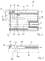
- FIGS. 2 and 3 A first embodiment is shown in FIGS. 2 and 3, with FIG. 2 the dust protection device (in a second swivel position) closed, in Fig. 3, however, is open (in a first pivot position). Even in these Figures is based on the socket part 10 of FIG. 1, the left Half in Fig. 2 and 3 is shown in longitudinal section. For the same parts the same reference numerals are used as in FIG. 1.
- the means for dustproof Complete i.e. the actual dust protection device, completely inside of the socket part 10, in particular within the inner socket housing 15 arranged.
- the dust protection means comprise two (rectangular) wings 36 and 41, which in the region of the insertion opening of the socket part 10 on opposite Sides of the inner socket housing 15 are pivoted inwards are.
- the wings 36, 41 lie essentially parallel to and close to the walls of the inner socket housing 15. This enables you to insert the plug part unhindered.
- the second Swivel position Fig. 2 they are pivoted to the center and come across in a horizontal The middle plane of the socket part 10 with its edges sealing against one another.
- the wings 36, 41 are by spring means, which are preferably in the form of two arms Have leaf springs 38 and 46, and as under reference numeral 30 are known from Fig. 1, held in the second pivot position (Fig. 2). At the Inserting a connector part will then be through the connector part against the Spring tension of the leaf springs 38, 46 pivoted into the first pivot position (Fig. 3). The automatic actuation by the plug part is thereby relieved that the wings 36, 41 obliquely in the second pivot position are directed inside. So that the wings 36, 41 are pivotable, are on them Articulated cams 37, 42 projecting laterally on both sides, with which the wings 36, 41 are used in storage grooves on the walls of the inner socket housing 15 are formed, and of which in Fig.
- the lower wing 36 is similar to that in the associated leaf spring 38 constructed as the radiation protection flap 26 from the known connector according to FIG. 1.
- the insertion opening does not close in the area of the guide groove 22 because the flap is simple Rectangle is formed on the lower wing 36 on both sides laterally protruding lugs 39 formed in the second pivot position (Fig. 2) protrude into the guide groove 22 and the insertion opening in cover this area.
- the recess 40 is designed so that the lateral lugs 39 when the lower wing is folded down into the first Swivel position (Fig. 3) without hindrance from the guide groove 22 down can be swung out.
- the upper wing 41 with its associated leaf spring 46 takes in the embodiment 2 and 3, the space in the known socket part from Fig. 1, the resilient tongue 16 with its pawl 16a claimed.
- a latching of the inserted Plug part in the socket part is possible, is on the bottom or outside of the upper wing 41, a pawl 44 is formed, which, if the upper wing 41 is in the first pivot position (Fig. 3), the place of Pawl 16a of Fig. 1 takes.
- the interaction of the upper wing 41 and the in the associated leaf spring 46 is tuned so that the upper wing 41 further beyond its horizontal position against the pressure of the spring can be pivoted above (dotted lines in Fig. 3).
- the pawl 44 on the underside of the upper wing 41 then gives the way for the to be inserted Plug part freely and then clicks behind the input provided on the plug part described, transverse locking bar. This way you can without Modification of the plug part in the socket part 10 with a dust protection according to 2 and 3 maintain the latching function in full.
- FIGS. 4 to 7 Another preferred embodiment of the invention, which also works with two wings to close the insertion opening and one 1, is shown in FIGS. 4 to 7, the 4 and 5 the second pivot position and FIGS. 6 and 7 the first pivot position - each seen from the side and from above - show in longitudinal section.
- the side wing 47 The other, Side wing, not shown, is a mirror image of the vertical center plane in Fig. 5 and 7 arranged.
- the side wings 47 - as the name suggests - each about a vertical axis arranged pivotally and bump in the second pivot position (Fig. 4 and 5) in a vertical median plane.
- the Side wings 47 each have an articulated cam 48 or 49 formed on them, with which the side wings 47 from the side through corresponding recesses 62 in the side wall in corresponding storage grooves in the floor or in the ceiling of the inner socket housing 15 are used and stored.
- the Side wings 47 are also inclined inwards and are replaced by a assigned leaf spring 50 in the direction of the second pivot position (FIG. 5) biased.
- the side wings pivoted out form 47 part of the side wall of the inner socket housing 15. If the guide grooves 20 and 22 already mentioned are let into the side walls are, it is appropriate if appropriate on the outer sides of the side wings Groove sections 59 and 60 are recessed, which when the side wings 47 are in the first pivot position, a portion of the guide grooves 20, 22 form. In this way, the side wings 47 save space in the Integrate side walls of the inner socket housing 15 without having to go through Guide grooves 20, 22 must be dispensed with. So that there is enough space for pivoting the side wings 47 there are resilient tongues 16 in the front area with a bevel 16b (Fig. 5 and 7).
Landscapes
- Physics & Mathematics (AREA)
- General Physics & Mathematics (AREA)
- Optics & Photonics (AREA)
- Mechanical Coupling Of Light Guides (AREA)
- Optical Couplings Of Light Guides (AREA)
- Cable Accessories (AREA)
- Light Guides In General And Applications Therefor (AREA)
- Sampling And Sample Adjustment (AREA)
- Insulated Conductors (AREA)
- Connector Housings Or Holding Contact Members (AREA)
Claims (4)
- Connecteur à fiches pour guide d'ondes lumineuses, comprenant une partie de douille (10) avec un logement de douille extérieur (11) ouvert au moins d'un côté, dans lequel une partie de fiche avec une broche d'enfichage renfermant un guide d'ondes lumineuses peut être enfichée par l'au moins un côté,a) une douille (25) ouverte vers l'au moins un côté étant disposée dans le logement de douille extérieur (11), laquelle douille reçoit lors de l'enfichage d'une partie de fiche à travers une ouverture d'enfichage correspondante (25a,b) la broche d'enfichage associée,b) des moyens (31; 39, 41; 47) disposés de façon à pouvoir pivoter sur la partie de douille (10) étant prévus, lesquels permettent, dans une première position de pivotement un enfichage non entravé de la partie de fiche, et dans une deuxième position de pivotement, isolent la douille (25) de manière hermétique à la poussière par rapport à l'environnement de la partie de douille (10),c) les moyens pour l'isolation hermétique à la poussière (39, 41; 47) étant complètement disposés à l'intérieur de la partie de douille (10),d) la partie de douille (10) comprenant un logement de douille intérieur (15), dans lequel la douille (25) est montée, et pouvant être enfoncé dans le logement de douille extérieur (11),e) les moyens pour l'isolation hermétique à la poussière comprenant chacun deux ailes (36, 41; 47) qui sont montées de manière à pouvoir pivoter vers l'intérieur dans la partie de l'ouverture d'enfichage de la partie de douille (10) sur des côtés opposés du logement de douille intérieur (15), et qui sont essentiellement parallèles aux parois du logement de douille intérieur (15) dans la première position de pivotement, et qui permettent un enfichage libre de la partie de fiche, et sont pivotées vers le centre dans la deuxième position de pivotement et s'appliquent l'une contre l'autre de manière hermétique dans un plan médian de la partie de douille (10), etf) les ailes (36, 41; 47) étant maintenues dans la deuxième position de pivotement par des moyens à ressort, de préférence sous la forme de ressorts à lames (38, 46; 50), de telle sorte qu'elles soient pivotées dans la première position de pivotement lors de l'enfichage d'une partie de fiche à travers la partie de douille à l'encontre de la tension de ressort des moyens à ressort (38, 46; 50),
caractérisé en ce que.g) un cliquet d'arrêt à ressort (44) est prévu dans le logement de douille intérieur (15) pour l'encliquetage desserrable d'une partie de fiche enfichée, en ce que le cliquet d'arrêt (44) est disposé à chaque fois du côté extérieur de l'une des ailes, de telle sorte que les moyens à ressort (46) associés à cette aile réalisent simultanément la sollicitation par ressort du cliquet d'arrêt (44). - Connecteur à fiches selon la revendication 1, caractérisé en ce que la partie de douille (10) est réalisée pour l'enfichage opposé de deux parties de fiche sur des côtés opposés, et en ce que les moyens (31; 39, 41; 47) disposés de manière à pouvoir pivoter sont prévus des deux côtés de la partie de douille (10).
- Connecteur à fiches pour guide d'ondes lumineuses, comprenant une partie de douille (10) avec un logement de douille extérieur (11) ouvert au moins d'un côté, dans lequel une partie de fiche avec une broche d'enfichage renfermant un guide d'ondes lumineuses peut être enfichée par l'au moins un côté,a) une douille (25) ouverte vers l'au moins un côté étant disposée dans le logement de douille extérieur (11), laquelle douille reçoit lors de l'enfichage d'une partie de fiche à travers une ouverture d'enfichage correspondante (25a,b) la broche d'enfichage associée,b) des moyens (31; 39, 41; 47; 57) disposés de façon à pouvoir pivoter sur la partie de douille (10) étant prévus, lesquels permettent, dans une première position de pivotement un enfichage non entravé de 1a partie de fiche, et dans une deuxième position de pivotement, isolent la douille (25) de manière hermétique à la poussière par rapport à l'environnement de la partie de douille (10),c) les moyens pour l'isolation hermétique à la poussière (39, 41; 47; 57) étant complètement disposés à l'intérieur de la partie de douille (10),d) la partie de douille (10) comprenant un logement de douille intérieur (15), dans lequel la douille (25) est montée, et pouvant être enfoncé dans le logement de douille extérieur (11),e) les moyens pour l'isolation hermétique à la poussière comprenant chacun deux ailes (36, 41; 47) qui sont montées de manière à pouvoir pivoter vers l'intérieur dans la partie de l'ouverture d'enfichage de la partie de douille (10) sur des côtés opposés du logement de douille intérieur (15), et qui sont essentiellement parallèles aux parois du logement de douille intérieur (15) dans la première position de pivotement, et qui permettent un enfichage libre de la partie de fiche, et sont pivotées vers le centre dans la deuxième position de pivotement et s'appliquent l'une contre l'autre de manière hermétique dans un plan médian de la partie de douille (10), etf) les ailes (36, 41; 47) étant maintenues dans la deuxième position de pivotement par des moyens à ressort, de préférence sous la forme de ressorts à lames (38, 46; 50), de telle sorte qu'elles soient pivotées dans la première position de pivotement lors de l'enfichage d'une partie de fiche à travers la partie de douille à l'encontre de la tension de ressort des moyens à ressort (38, 46; 50),
caractérisé en ce queg) des rainures de guidage (20, 22) pour le guidage de la partie de fiche lors de l'enfichage sont prévues dans les parois latérales du logement de douille intérieur (15), et en ce que les ailes (47) sont pourvues sur leurs côtés extérieurs de portions de rainures (59, 60) qui, lorsque les ailes (47) se trouvent dans la première position de pivotement, forment une portion des rainures de guidage (20, 22). - Connecteur à fiches selon la revendication 3, caractérisé en ce que la partie de douille (10) est réalisée pour l'enfichage opposé de deux parties de fiche sur des côtés opposés, et en ce que les moyens (31; 39, 41; 47) disposés de manière à pouvoir pivoter sont prévus des deux côtés de la partie de douille (10).
Applications Claiming Priority (3)
| Application Number | Priority Date | Filing Date | Title |
|---|---|---|---|
| CH158398 | 1998-07-27 | ||
| CH158398 | 1998-07-27 | ||
| EP99810547A EP0977062B1 (fr) | 1998-07-27 | 1999-06-21 | Prise de connexion pour des guides d'ondes lumineuses |
Related Parent Applications (2)
| Application Number | Title | Priority Date | Filing Date |
|---|---|---|---|
| EP99810547.2 Division | 1999-06-21 | ||
| EP99810547A Division EP0977062B1 (fr) | 1998-07-27 | 1999-06-21 | Prise de connexion pour des guides d'ondes lumineuses |
Publications (3)
| Publication Number | Publication Date |
|---|---|
| EP1128199A1 EP1128199A1 (fr) | 2001-08-29 |
| EP1128199B1 true EP1128199B1 (fr) | 2002-11-27 |
| EP1128199B8 EP1128199B8 (fr) | 2003-07-02 |
Family
ID=4213811
Family Applications (2)
| Application Number | Title | Priority Date | Filing Date |
|---|---|---|---|
| EP99810547A Expired - Lifetime EP0977062B1 (fr) | 1998-07-27 | 1999-06-21 | Prise de connexion pour des guides d'ondes lumineuses |
| EP01201654A Expired - Lifetime EP1128199B8 (fr) | 1998-07-27 | 1999-06-21 | Prise de connexion pour des guides d'ondes lumineuses |
Family Applications Before (1)
| Application Number | Title | Priority Date | Filing Date |
|---|---|---|---|
| EP99810547A Expired - Lifetime EP0977062B1 (fr) | 1998-07-27 | 1999-06-21 | Prise de connexion pour des guides d'ondes lumineuses |
Country Status (6)
| Country | Link |
|---|---|
| US (1) | US6302592B1 (fr) |
| EP (2) | EP0977062B1 (fr) |
| JP (1) | JP2000047060A (fr) |
| AT (2) | ATE220212T1 (fr) |
| DE (2) | DE59901904D1 (fr) |
| DK (1) | DK1128199T3 (fr) |
Families Citing this family (25)
| Publication number | Priority date | Publication date | Assignee | Title |
|---|---|---|---|---|
| US5883995A (en) | 1997-05-20 | 1999-03-16 | Adc Telecommunications, Inc. | Fiber connector and adapter |
| US6695485B1 (en) * | 2000-07-28 | 2004-02-24 | Tellabs Operations, Inc. | Bezel for fiber optic components |
| US6572274B1 (en) | 2001-11-29 | 2003-06-03 | Lynx Photonic Networks Inc. | Safety shutter module for fiber-optics connector |
| US6688780B2 (en) | 2002-02-07 | 2004-02-10 | Amphenol Corporation | Cantilevered shutter for optical adapter |
| US6682228B2 (en) | 2002-02-19 | 2004-01-27 | Emcore Corporation | Connector housing for fiber-optic module |
| GB0208464D0 (en) * | 2002-04-12 | 2002-05-22 | Schott Fibre Optics Uk Ltd | Fibre optic lighting systems |
| US7144163B2 (en) * | 2003-01-27 | 2006-12-05 | Fujikura Ltd. | Optical connector with shutter, shutter unit, and inner piece |
| JP2005189332A (ja) * | 2003-12-24 | 2005-07-14 | Three M Innovative Properties Co | 光コネクタ、コネクタ付き光ファイバ、光ファイバ接続装置及び光ファイバ接続方法 |
| DE102004025512A1 (de) * | 2004-05-21 | 2005-12-15 | Neutrik Aktiengesellschaft | Einrichtung für eine optische Steckverbindung |
| JP4416591B2 (ja) * | 2004-07-16 | 2010-02-17 | スリーエム イノベイティブ プロパティズ カンパニー | 光コネクタ及び光ファイバ接続システム |
| JP4544928B2 (ja) * | 2004-07-16 | 2010-09-15 | スリーエム イノベイティブ プロパティズ カンパニー | 光コネクタ及び光ファイバ接続システム |
| US7390203B2 (en) * | 2006-10-11 | 2008-06-24 | Ortronics, Inc. | Secure fiber optic network keyed connector assembly |
| DE102008033232A1 (de) | 2008-07-15 | 2010-01-21 | Neutrik Aktiengesellschaft | Steckerteil für eine optische Steckverbindung |
| US7785018B2 (en) * | 2008-08-29 | 2010-08-31 | Corning Cable Systems Llc | Fiber optic adapters with integrated shutter |
| CN101854007B (zh) * | 2009-04-02 | 2012-08-29 | 富士康(昆山)电脑接插件有限公司 | 电连接器 |
| CN101872041B (zh) * | 2009-04-27 | 2012-08-29 | 富士康(昆山)电脑接插件有限公司 | 光电连接器 |
| JP2010281910A (ja) * | 2009-06-02 | 2010-12-16 | Japan Aviation Electronics Industry Ltd | 光コネクタ装置 |
| US9196997B2 (en) * | 2011-11-10 | 2015-11-24 | Panduit Corp. | Shuttered LC adapter |
| US9494746B2 (en) | 2011-11-10 | 2016-11-15 | Panduit Corp. | Shuttered LC adapter |
| CN104067154A (zh) | 2012-02-24 | 2014-09-24 | 惠普发展公司,有限责任合伙企业 | 光学盲配式连接器 |
| DE102013005226B4 (de) * | 2013-03-27 | 2017-11-16 | Krohne Messtechnik Gmbh | Messgerät |
| US10345536B2 (en) * | 2015-01-06 | 2019-07-09 | Commscope Telecommunications (Shanghai) Co., Ltd. | Optical fiber connector and method of attaching and detaching same |
| CN108139547B (zh) * | 2015-10-12 | 2020-09-08 | 3M创新有限公司 | 多波导连接器中的光波导定位特征结构 |
| WO2017081298A1 (fr) * | 2015-11-13 | 2017-05-18 | CommScope Connectivity Belgium BVBA | Système d'obturateur pour adaptateur de fibre optique |
| WO2022226406A1 (fr) | 2021-04-23 | 2022-10-27 | Commscope Technologies Llc | Système de panneau à connectivité gérée |
Family Cites Families (19)
| Publication number | Priority date | Publication date | Assignee | Title |
|---|---|---|---|---|
| US4673242A (en) | 1981-12-21 | 1987-06-16 | Thomas & Betts Corporation | Movable closure for optical elements |
| JPH06100698B2 (ja) * | 1984-06-08 | 1994-12-12 | アンプ・インコ−ポレ−テッド | 光ファイバコネクタ組立体 |
| US4640575A (en) * | 1986-01-13 | 1987-02-03 | Rockwell International Corporation | Fiber optic connector cover apparatus |
| JPS63118707A (ja) * | 1986-11-07 | 1988-05-23 | Hitachi Ltd | プラグイン光コネクタ |
| JPH039308A (ja) * | 1989-06-07 | 1991-01-17 | Fujitsu Ltd | レーザハザード防止機構 |
| DE59205913D1 (de) * | 1992-05-20 | 1996-05-09 | Diamond Sa | Steckverbindung für Lichtwellenleiter |
| AU658999B2 (en) * | 1992-05-20 | 1995-05-04 | Diamond S.A. | Plug connector for optical fibers |
| AU660859B2 (en) | 1992-11-26 | 1995-07-06 | Diamond S.A. | Sleeve portion for an optical fibre plug connector |
| US5506922A (en) * | 1994-08-01 | 1996-04-09 | Molex Incorporated | Fiber optic component assembly with a movable protective shield |
| JPH08125615A (ja) * | 1994-10-20 | 1996-05-17 | Fujitsu Ltd | レーザ光漏洩防止装置 |
| US6086263A (en) * | 1996-06-13 | 2000-07-11 | 3M Innovative Properties Company | Active device receptacle |
| AU719299B2 (en) | 1996-08-08 | 2000-05-04 | Diamond S.A. | Plug portion for an optical fiber connector |
| US5956444A (en) * | 1997-02-13 | 1999-09-21 | Amphenol Corporation | Radiation absorbing shield for fiber optic systems |
| US5896477A (en) * | 1997-05-16 | 1999-04-20 | Lucent Technologies Inc. | Optical fiber coupling buildout system |
| US5883995A (en) * | 1997-05-20 | 1999-03-16 | Adc Telecommunications, Inc. | Fiber connector and adapter |
| EP0893716A1 (fr) * | 1997-07-21 | 1999-01-27 | Diamond S.A. | Douille en particulier pour une connexion optique et connecteur pour fibres optiques |
| US6041155A (en) * | 1997-12-10 | 2000-03-21 | Lucent Technologies Inc. | Universal dust cover |
| US6081647A (en) * | 1998-01-05 | 2000-06-27 | Molex Incorporated | Fiber optic connector receptacle |
| US5909526A (en) * | 1998-04-08 | 1999-06-01 | Molex Incorporated | Fiber optic connector assembly |
-
1999
- 1999-06-21 DE DE59901904T patent/DE59901904D1/de not_active Expired - Lifetime
- 1999-06-21 DK DK01201654T patent/DK1128199T3/da active
- 1999-06-21 EP EP99810547A patent/EP0977062B1/fr not_active Expired - Lifetime
- 1999-06-21 AT AT99810547T patent/ATE220212T1/de not_active IP Right Cessation
- 1999-06-21 EP EP01201654A patent/EP1128199B8/fr not_active Expired - Lifetime
- 1999-06-26 DE DE50100218T patent/DE50100218D1/de not_active Expired - Fee Related
- 1999-06-26 AT AT01201654T patent/ATE228662T1/de not_active IP Right Cessation
- 1999-07-19 US US09/356,737 patent/US6302592B1/en not_active Expired - Fee Related
- 1999-07-27 JP JP11212473A patent/JP2000047060A/ja active Pending
Also Published As
| Publication number | Publication date |
|---|---|
| ATE220212T1 (de) | 2002-07-15 |
| DE50100218D1 (de) | 2003-06-12 |
| EP0977062A2 (fr) | 2000-02-02 |
| EP0977062B1 (fr) | 2002-07-03 |
| EP1128199A1 (fr) | 2001-08-29 |
| JP2000047060A (ja) | 2000-02-18 |
| ATE228662T1 (de) | 2002-12-15 |
| EP0977062A3 (fr) | 2000-11-29 |
| EP1128199B8 (fr) | 2003-07-02 |
| DE59901904D1 (de) | 2002-08-08 |
| DK1128199T3 (da) | 2003-03-24 |
| US6302592B1 (en) | 2001-10-16 |
Similar Documents
| Publication | Publication Date | Title |
|---|---|---|
| EP0977062B1 (fr) | Prise de connexion pour des guides d'ondes lumineuses | |
| EP0570652B1 (fr) | Connecteur pour fibres optiques | |
| EP1974976B1 (fr) | Tubulures de remplissage d'un réservoir de carburant dotées d'une protection contre les problèmes de remplissage de réservoir | |
| DE69834165T2 (de) | Universalstaubabdeckung | |
| DE60125996T2 (de) | Faseroptische Verbindungsbuchse | |
| EP2288951B1 (fr) | Boîtier de connexion pour câble à fibres optiques et tableau associé | |
| DE69512165T2 (de) | Faseroptische Anordnung mit beweglicher Schutzblende | |
| DE69316049T2 (de) | Zusammenbau von gestapelten Gelenkmodulen | |
| EP0599784B1 (fr) | Douille pour un terminal de connexion à fibre optique | |
| DE69409634T2 (de) | Behaelter fuer faseroptische spleisse | |
| DE3642424A1 (de) | Informationsverarbeitungseinrichtung fuer ic-karten | |
| EP0823649A1 (fr) | Elément de connecteur pour connexion optique | |
| EP1504296B1 (fr) | Connecteur optique | |
| DE102022001876A1 (de) | Fahrzeug mit einem Abdeckelement und einem Bewegungsmechanismus zum Bewegen des Abdeckelementes | |
| WO2000067055A1 (fr) | Fiche de raccordement pour guides d'ondes optiques | |
| EP1598685A1 (fr) | Dispositif pour un raccordement optique enfichable | |
| DE69216737T2 (de) | Magnetbandkassette | |
| DE3036765C2 (de) | Vorrichtung an einer Plattform eines Lastwagens zum lösbaren Verbinden zweier gegeneinander bewegbarer Teile | |
| EP3627199A1 (fr) | Adaptateur duplex | |
| DE19901447C2 (de) | Steckverbindung für Lichtwellenleiter | |
| DE29608029U1 (de) | Wandauslaß für Telekommunikationskabel | |
| DE20002200U1 (de) | Unterflurgerätedose | |
| DE29720815U1 (de) | Sicherungsvorrichtung für elektrische Steckverbindungen | |
| EP1037078A1 (fr) | Elément de protection pour couvrir une surface émettant de la lumière dans un composant optique, en particulier dans un connecteur optique | |
| DE9410996U1 (de) | Steckverbinder mit einem arretierbaren Verriegelungsbügel |
Legal Events
| Date | Code | Title | Description |
|---|---|---|---|
| PUAI | Public reference made under article 153(3) epc to a published international application that has entered the european phase |
Free format text: ORIGINAL CODE: 0009012 |
|
| AC | Divisional application: reference to earlier application |
Ref document number: 977062 Country of ref document: EP |
|
| AK | Designated contracting states |
Kind code of ref document: A1 Designated state(s): AT BE CH CY DE DK ES FI FR GB GR IE IT LI LU MC NL PT SE |
|
| AX | Request for extension of the european patent |
Free format text: AL;LT;LV;MK;RO;SI |
|
| RIN1 | Information on inventor provided before grant (corrected) |
Inventor name: ZUELLIG, MARC-ANDREW |
|
| 17P | Request for examination filed |
Effective date: 20011004 |
|
| GRAG | Despatch of communication of intention to grant |
Free format text: ORIGINAL CODE: EPIDOS AGRA |
|
| AKX | Designation fees paid | ||
| GRAG | Despatch of communication of intention to grant |
Free format text: ORIGINAL CODE: EPIDOS AGRA |
|
| GRAH | Despatch of communication of intention to grant a patent |
Free format text: ORIGINAL CODE: EPIDOS IGRA |
|
| 17Q | First examination report despatched |
Effective date: 20020430 |
|
| RBV | Designated contracting states (corrected) |
Designated state(s): AT BE CH CY DE DK ES FI FR GB GR IE IT LI LU MC NL PT SE |
|
| REG | Reference to a national code |
Ref country code: DE Ref legal event code: 8566 |
|
| GRAH | Despatch of communication of intention to grant a patent |
Free format text: ORIGINAL CODE: EPIDOS IGRA |
|
| GRAA | (expected) grant |
Free format text: ORIGINAL CODE: 0009210 |
|
| AC | Divisional application: reference to earlier application |
Ref document number: 977062 Country of ref document: EP |
|
| AK | Designated contracting states |
Kind code of ref document: B1 Designated state(s): AT BE CH CY DE DK ES FI FR GB GR IE IT LI LU MC NL PT SE |
|
| PG25 | Lapsed in a contracting state [announced via postgrant information from national office to epo] |
Ref country code: FI Free format text: LAPSE BECAUSE OF FAILURE TO SUBMIT A TRANSLATION OF THE DESCRIPTION OR TO PAY THE FEE WITHIN THE PRESCRIBED TIME-LIMIT Effective date: 20021127 Ref country code: GR Free format text: LAPSE BECAUSE OF FAILURE TO SUBMIT A TRANSLATION OF THE DESCRIPTION OR TO PAY THE FEE WITHIN THE PRESCRIBED TIME-LIMIT Effective date: 20021127 Ref country code: IE Free format text: LAPSE BECAUSE OF FAILURE TO SUBMIT A TRANSLATION OF THE DESCRIPTION OR TO PAY THE FEE WITHIN THE PRESCRIBED TIME-LIMIT Effective date: 20021127 |
|
| REF | Corresponds to: |
Ref document number: 228662 Country of ref document: AT Date of ref document: 20021215 Kind code of ref document: T |
|
| REG | Reference to a national code |
Ref country code: GB Ref legal event code: FG4D Free format text: NOT ENGLISH |
|
| REG | Reference to a national code |
Ref country code: CH Ref legal event code: EP |
|
| GBT | Gb: translation of ep patent filed (gb section 77(6)(a)/1977) |
Effective date: 20021127 |
|
| REG | Reference to a national code |
Ref country code: IE Ref legal event code: FG4D Free format text: GERMAN |
|
| REG | Reference to a national code |
Ref country code: CH Ref legal event code: NV Representative=s name: ISLER & PEDRAZZINI AG |
|
| PG25 | Lapsed in a contracting state [announced via postgrant information from national office to epo] |
Ref country code: SE Free format text: LAPSE BECAUSE OF FAILURE TO SUBMIT A TRANSLATION OF THE DESCRIPTION OR TO PAY THE FEE WITHIN THE PRESCRIBED TIME-LIMIT Effective date: 20030227 Ref country code: PT Free format text: LAPSE BECAUSE OF FAILURE TO SUBMIT A TRANSLATION OF THE DESCRIPTION OR TO PAY THE FEE WITHIN THE PRESCRIBED TIME-LIMIT Effective date: 20030227 |
|
| REG | Reference to a national code |
Ref country code: DK Ref legal event code: T3 |
|
| ET | Fr: translation filed | ||
| PG25 | Lapsed in a contracting state [announced via postgrant information from national office to epo] |
Ref country code: ES Free format text: LAPSE BECAUSE OF FAILURE TO SUBMIT A TRANSLATION OF THE DESCRIPTION OR TO PAY THE FEE WITHIN THE PRESCRIBED TIME-LIMIT Effective date: 20030529 |
|
| REG | Reference to a national code |
Ref country code: CH Ref legal event code: PK Free format text: DAS RICHTIGE ANMELDEDATUM LAUTET: 21.06.1999. |
|
| REF | Corresponds to: |
Ref document number: 50100218 Country of ref document: DE Date of ref document: 20030612 Kind code of ref document: P |
|
| PG25 | Lapsed in a contracting state [announced via postgrant information from national office to epo] |
Ref country code: LU Free format text: LAPSE BECAUSE OF NON-PAYMENT OF DUE FEES Effective date: 20030621 Ref country code: CY Free format text: LAPSE BECAUSE OF FAILURE TO SUBMIT A TRANSLATION OF THE DESCRIPTION OR TO PAY THE FEE WITHIN THE PRESCRIBED TIME-LIMIT Effective date: 20030621 |
|
| PG25 | Lapsed in a contracting state [announced via postgrant information from national office to epo] |
Ref country code: AT Free format text: LAPSE BECAUSE OF NON-PAYMENT OF DUE FEES Effective date: 20030626 Ref country code: GB Free format text: LAPSE BECAUSE OF NON-PAYMENT OF DUE FEES Effective date: 20030626 |
|
| PG25 | Lapsed in a contracting state [announced via postgrant information from national office to epo] |
Ref country code: DK Free format text: LAPSE BECAUSE OF NON-PAYMENT OF DUE FEES Effective date: 20030630 Ref country code: CH Free format text: LAPSE BECAUSE OF NON-PAYMENT OF DUE FEES Effective date: 20030630 Ref country code: MC Free format text: LAPSE BECAUSE OF NON-PAYMENT OF DUE FEES Effective date: 20030630 Ref country code: LI Free format text: LAPSE BECAUSE OF NON-PAYMENT OF DUE FEES Effective date: 20030630 |
|
| REG | Reference to a national code |
Ref country code: IE Ref legal event code: FD4D Ref document number: 1128199E Country of ref document: IE |
|
| NLXE | Nl: other communications concerning ep-patents (part 3 heading xe) |
Free format text: PAT. BUL. 05/2003: THE FILING DATE SHOULD BE MODIFIED INTO 19990621 (SEE EUROPEAN PATENT BULLETIN 20030604/23) |
|
| PLBE | No opposition filed within time limit |
Free format text: ORIGINAL CODE: 0009261 |
|
| STAA | Information on the status of an ep patent application or granted ep patent |
Free format text: STATUS: NO OPPOSITION FILED WITHIN TIME LIMIT |
|
| 26N | No opposition filed |
Effective date: 20030828 |
|
| BERE | Be: lapsed |
Owner name: *HUBER & SUHNER A.G. Effective date: 20030630 |
|
| PG25 | Lapsed in a contracting state [announced via postgrant information from national office to epo] |
Ref country code: NL Free format text: LAPSE BECAUSE OF NON-PAYMENT OF DUE FEES Effective date: 20040101 Ref country code: DE Free format text: LAPSE BECAUSE OF NON-PAYMENT OF DUE FEES Effective date: 20040101 |
|
| REG | Reference to a national code |
Ref country code: DK Ref legal event code: EBP |
|
| REG | Reference to a national code |
Ref country code: CH Ref legal event code: PL |
|
| GBPC | Gb: european patent ceased through non-payment of renewal fee |
Effective date: 20030626 |
|
| PG25 | Lapsed in a contracting state [announced via postgrant information from national office to epo] |
Ref country code: FR Free format text: LAPSE BECAUSE OF NON-PAYMENT OF DUE FEES Effective date: 20040227 |
|
| NLV4 | Nl: lapsed or anulled due to non-payment of the annual fee |
Effective date: 20040101 |
|
| REG | Reference to a national code |
Ref country code: FR Ref legal event code: ST |
|
| PG25 | Lapsed in a contracting state [announced via postgrant information from national office to epo] |
Ref country code: IT Free format text: LAPSE BECAUSE OF NON-PAYMENT OF DUE FEES Effective date: 20050621 |
|
| PG25 | Lapsed in a contracting state [announced via postgrant information from national office to epo] |
Ref country code: BE Free format text: LAPSE BECAUSE OF NON-PAYMENT OF DUE FEES Effective date: 20030630 |