EP1128328A2 - Pipeline de rendu des éléments de surface - Google Patents
Pipeline de rendu des éléments de surface Download PDFInfo
- Publication number
- EP1128328A2 EP1128328A2 EP01102241A EP01102241A EP1128328A2 EP 1128328 A2 EP1128328 A2 EP 1128328A2 EP 01102241 A EP01102241 A EP 01102241A EP 01102241 A EP01102241 A EP 01102241A EP 1128328 A2 EP1128328 A2 EP 1128328A2
- Authority
- EP
- European Patent Office
- Prior art keywords
- octree
- tuples
- surfel
- rendering
- texture
- Prior art date
- Legal status (The legal status is an assumption and is not a legal conclusion. Google has not performed a legal analysis and makes no representation as to the accuracy of the status listed.)
- Withdrawn
Links
Images







Classifications
-
- G—PHYSICS
- G06—COMPUTING OR CALCULATING; COUNTING
- G06T—IMAGE DATA PROCESSING OR GENERATION, IN GENERAL
- G06T15/00—Three-dimensional [3D] image rendering
- G06T15/005—General purpose rendering architectures
Definitions
- This invention relates generally to graphic rendering, and more particularly to rendering zero-dimensional surface elements of graphic objects using a pipelined rendering engine.
- Three-dimensional computer graphics have become ubiquitous at the consumer level. There is a proliferation of affordable 3D graphics hard ware accelerators, from high-end PC workstations to low-priced game stations.
- interactive computer graphics have still not reached the level of realism that allows a true immersion into a virtual world.
- typical foreground characters in real-time games are extremely minimalistic polygon models that often exhibit annoying artifacts, such as angular silhouettes.
- Textures convey more detail inside a polygon, thereby allowing larger and fewer triangles to be used.
- Today's graphics engines are highly tailored for high texture mapping performance.
- texture maps have to follow the underlying geometry of the polygon model and work best on flat or slightly curved surfaces. Realistic or "organic" surfaces frequently require a large number of textures that have to be applied in multiple passes during rasterization.
- Advanced rendering techniques such as Phong shading, bump mapping, and displacement mapping, are not handled by most current consumer graphics systems. Graphic phenomena such as smoke, fire, or water are difficult to render using textured triangles.
- 3D objects have been geometrically modeled as a mesh of polygonal facets.
- the polygons are triangles.
- the size of each facet is made to correspond mostly to the degree of curvature of the object in the region of the facet.
- Many polygons are needed where the object has a high degree of curvature, fewer for relatively flat regions.
- Polygon models are used in many applications, such as, virtual training environments, 3D modeling tools, and video games. As a characteristic, geometric representations only deal with the surface features of graphic objects.
- the object is sampled in 3D space to generate a volumetric data set, for example, a MRI or CT scan.
- a volumetric data set for example, a MRI or CT scan.
- Each sample is called a voxel.
- a typical data set may include millions of voxels.
- the object is typically segmented. Iso-surfaces can be identified to focus on specific volumetric regions. For instance, a volumetric data set of the human head may segment the voxels according to material properties, such as bone and soft tissue.
- a point sample representation of objects is often used to model fluid flows, for example, in wind tunnel simulations. Certain attributes, such as orientation velocity, are given to point samples in order to track individual point samples through the fluid flow, or to visualize the complete flow.
- point sample representation is in the visualization of "cloud-like" objects, such as smoke, dust or mist.
- a shading model can be applied to point samples that emit light to render cloud-like objects.
- point samples can be constrained to subspaces with the help of energy functions to model surfaces.
- An advantage of point sample clouds is that the clouds are very deformable. As a disadvantage, the point samples in the cloud are unconnected and behave individually when exposed to forces. Furthermore, prior art point samples are quite unsuitable for representing surfaces of solid objects or models.
- the rendering time for these conventional primitives depends on the complexity of the objects modeled.
- the polygons are typically very small in size, in the order of a very small number of pixels, and the object is represented by many polygons.
- the polygons are usually represented with vertices that define a triangle.
- the projection of the triangle is scan-converted (rasterized) to calculate the intensity of each pixel that falls within the projection. This is a relatively time consuming operation when only a few pixels are covered by each polygon. Replacing the polygons with point samples and projecting the point samples to the image can be a more efficient technique to render objects.
- volume rendering is quite complex. Unless the number of voxels is limited, real-time rendering can be time consuming, or impractical for real-time applications.
- a real-time rendering system described in U.S. Patent No. 5,781,194 "Real-time Projection of Voxel-based Objects," issued to Ponomarov et al. on July 14, 1998, constructs a chain of surface voxels using incremental vectors between surface voxels. That representation succeeds in modeling and displaying objects showing highly detailed surface regions.
- the modeling of rigid body motion is done with the aid of scripting mechanisms that lack realism because physically-based methods are not used.
- view-dependent, image centered samples to represent an object or scene.
- view-dependent samples are ineffective for dynamic scenes with motion of objects, changes in material properties, and changes in position and intensities of light sources.
- the coverage is estimated by calculating the density of the projected points in image space and the weighting is modeled with a Gaussian filter.
- An enhanced depth-buffer (z-buffer) allows for depth comparisons with a tolerance that enables the blending of points in a small region of depth-values. Their point representation allows one to render the object from any point of view.
- the point samples are obtained by sampling orthographic projections of an object on an equilateral triangle lattice.
- the equilateral triangle lattice was preferred to a quadrilateral one because the spacing between adjacent sampling points is more regular.
- the present invention provides a method for rendering objects with rich shapes and textures at interactive frame rates.
- the method is based on surface elements ( surfels ) as rendering primitives.
- Surfels are point samples of a graphics model.
- the invention adaptively samples the object using image space resolution.
- computation-intensive calculations such as texture, bump, or displacement mapping are performed.
- the surfel representation according to the invention provides a discretization of the geometry, and hence, reduces the object representation to the essentials needed for rendering.
- triangle primitives implicitly store connectivity information, such as vertex valence or adjacency - data not necessarily available or needed for rendering.
- the rendering also provides environment mapping with a painterly surfel rendering process running at interactive frame rates.
- a hierarchical forward projection algorithm allows one to estimate the surfel density per output pixel for speed-quality tradeoffs.
- a surfel rendering pipeline complements existing graphics pipelines.
- the pipeline trades memory overhead for rendering performance and quality.
- the present invention is suitable for interactive 3D applications, particularly for organic objects with high surface details, and for applications where preprocessing is not an issue. These qualities make the present invention ideal for interactive games.
- Surfels according to the invention are a powerful paradigm to efficiently render complex geometric objects at interactive frame rates. Unlike classical surface discretizations, i.e., triangles or quadrilateral meshes, surfels are point primitives without explicit connectivity. Surfel attributes comprise depth, texture color, normal, and others. As a preprocess, an octree-based surfel representation of a geometric object is constructed. During sampling, surfel positions and normals are optionally perturbed, and different levels of texture colors are prefiltered and stored per surfel in a view independent manner.
- a hierarchical forward warping algorithm projects surfels to a z-buffer (depth buffer).
- a novel method called visibility splatting determines visible surfels and holes in the z-buffer. Visible surfels are shaded using texture filtering, Phong illumination, and environment mapping using per-surfel normals.
- image reconstruction including supersampling, offer flexible speed-quality tradeoffs. Due to the simplicity of the operations, the surfel rendering pipeline is amenable for a hardware implementation. Surfel objects offer complex shape, low rendering cost and high image quality, which makes them specifically suited for low-cost, real-time graphics, such as games.
- a rendering system includes a memory storing shape and shade attributes of a surface of the object.
- the attributes are arranged as an octree in the memory.
- the octree includes a plurality of nodes arranged at a plurality of levels, each node storing a plurality of zero-dimensional n-tuples, each n-tuple locally approximating the shape and shade attributes of a portion of the surface of the graphic object, and the n-tuples having a sampling resolution of an image space.
- a plurality of parallel processing pipelines are connected the memory. The pipelines project the shape and shade attributes of the octree to an image plane having a selected orientation by traversing the n-tuples of the nodes of the octree from a lowest resolution level to a highest resolution level.
- the graphic object is sampled by casting rays through the object.
- the rays originate at orthogonal planes surrounding the object.
- the surface of the object is sampled for shape and shade attributes at points where the rays intersect the surface.
- the sampled shape and shade attributes of each sampled point are stored in the octree stored in the memory.
- Shade attributes of the surface points of the a graphic object are filtered by constructing tangential disks at positions of each surface point.
- the tangential disks have increasingly larger radii.
- Each tangential disk is projected to an ellipse in texture space.
- View independent filter functions are applied at the position of each surface point to generate texture mipmaps for the surface point.
- the filter functions have an extent equal to the projected tangential disk.
- the surface point is projected to the pixels in the depth buffer, and a view dependent filter function is applied to each pixel in the image buffer to determine colors for the pixels.
- surfels We describe an image-based adaptive sampling and object-based rendering of graphic objects represented as surface elements, i.e., "surfels.”
- a surfel 100 As shown in Figure 1, we define a surfel 100 as a zero-dimensional n-tuple with shade and shape attributes that locally approximates a portion 101 of a surface 102 of a graphic object 103.
- the shape attributes can include position, orientation, and depth information of the object.
- the shade attributes can include texture, material properties, and opacity.
- we store surfels as a reduced layered depth cube (LDC) tree.
- LDC reduced layered depth cube
- the surfel representation of our invention is a projection of an image space resolution into the object space, resulting in an arbitrary 2D manifold.
- our surfel position attributes have object space coordinates with image space resolution.
- Surfel manifolds can be connected to each other to form a more complex 2D manifold.
- the manifold "outlines" arbitrary objects, real or imagined.
- prior art rendering primitives are usually sampled with an object space resolution.
- Our representation combines object space rendering and image space sampling by defining a mapping between object surfels and image plane pixels. Surfels are generated according to the image resolution. Thus, no detail smaller than a pixel is considered when sampling the object.
- Sampling according to the image space resolution provides a direct correspondence between sampled object space and image space. By defining surfels this way, rendering of objects becomes easier in the sense that resampling of the object is not required during rendering, no matter what the viewing direction. Thus, rendering "surfelized" objects is more efficient.
- a surfel grid, with image space resolution, allows us to render presampled objects for any viewing direction.
- Table A compares prior art polygons, voxels, and point samples with surfels according to our invention. The table shows that our surfels have attributes similar to known prior art representation primitives.
- a surfel has the attributes of a pixel of a converted polygon when the polygon has a size of about one pixel.
- a surfel can also be considered as an extracted 8-connected surface voxel, where the cell in which the surfel is located has a dimension of 1 ⁇ 1 ⁇ 1 pixel, and has six adjacent surfels.
- a surfel object can also be thought of as a mapping of a particle cloud that is defined on the resolution of the image grid.
- Surfels also have differences. For example, surfels are unlike voxels and particles in their geometry. Surfels are unlike polygons and particles with respect to a grid. Surfels are unlike voxels and particles in the way that neighboring elements are related. Surfels are unlike points in that they are sampled according to an expected output screen resolution and not according to object space criteria. Surfels also are different from points in that they have not an explicit but an implicit connectivity that arises from the discrete surfel sampling grid.
- graphic objects include just enough surfels to reconstruct the surface of the object by a simple projection of the surfels to an image plane, followed by image reconstruction.
- a rectangular surfel polygon of 100 by 100 surfels will produce 100 by 100 pixels on the image plane.
- the image plane is physically expressed as pixels in an image buffer. Normally, the contribution of a surfel to the image will be about one to one.
- Our invention deals with graphic objects in two stages, preprocessing and rendering.
- a preprocessing stage we sample a graphic object and then filter the sampled data. We preprocess a particular graphic object only once. The sampling can be done by software programs. Because this is a one time operation, sophisticated techniques can be used to extract as much attribute information from the object as possible, and to reduce the sampled object to a data structure that is efficient to render for any viewing direction to produce quality images.
- the rendering stage we render the data structure.
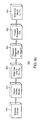
- FIG. 2 is a high level block diagram of a sampling preprocessing stage 200.
- An adaptive sampling process 210 converts a graphic object 201 and its textures attributes to surfels 211.
- ray casting we use ray casting to arrange the surfels in three orthogonal layered depth images (LDIs).
- the LDIs store multiple surfels along each ray, one for each ray-surface intersection point.
- LDC layered depth cube
- a prefiltering step 220 is described in greater detail below.
- the main purpose of this step is to extract view-independent texture attributes of the blocks.
- a LDC "block” is attached to each leaf node of an octree 221.
- Octrees are well known in computer graphics see for example, Veenstra et al. in "Line drawings of octree-represented objects, ACM Transactions on Graphics, Vol.7, No. 1, pp. 61-75, January 1988.
- the octree is used to index three dimensions.
- Each level of our LDC tree corresponds to a different resolution of the surfel object.
- a data reduction step 230 we optionally reduce each block tree to a reduced LDC tree 231. Preferrably, the reduction can be three to one. This reduces storage costs, and further improves rendering performance.
- sampling shape (geometry) and sampling shade , (texture color).
- a surfel stores shape attributes, such as surface position, and orientation, e.g., the surface normal 104 in Figure 1.
- the x-y position is implicitly defined by the location of the block (node) in the LDC tree 221, that is, explicit xy coordinates are not stored.
- Depth information ( z coordinates) are explicitly stored in the octree.
- the orientation of the surface is given by the surface normal 104, see Figure 1. Instead of actually storing a normal, we store an index to a quantized normal table that is used during reflection and environment map shading.
- the shape attributes are based on object space.
- Shade is expressed as multiple levels of prefiltered texture colors. We call this novel hierarchical color information a surfel texture mipmap.
- other view-independent methods such as bump and displacement mapping, can also be performed to extracted shape and shade attributes.
- Table B gives the minimum storage requirements per surfel.
- Data Field Storage Three Surfel Texture Mipmap Levels 3 x 24 bits Index to Normal Table 16 bits LDI Depth Value 32 bits Index to Material Table 16 bits Total Bytes per Surfel 17 bytes
- the size of the LDC tree is about a factor of two larger than the sampled data due to overhead, e.g., pointers, in the octree data structure.
- the LDC tree can be substantially compressed by run length coding or wavelet-based compression techniques.
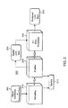
- Figure 3 shows a rendering pipeline 300 for our surfels.
- the pipeline hierarchically projects the blocks (nodes) of the LDC tree blocks to pixels of the image plane 399 using perspective projection.
- the orientation of the image plane for the purpose of rendering can be arbitrary, and different than the orientation of the three orthogonal depth images used during sampling.
- the rendering is accelerated by block culling 310 and fast incremental forward warping 320.
- a depth-buffer (z-buffer), together with a novel method called visibility splatting 330 solves a visibility problem.
- tangential disks, at each surfel are scan-converted into a z-buffer in order to detect surface holes and prevent hidden (occluded) surfels from being used in the reconstruction process.
- Texture colors of visible surfels are filtered 340 using linear interpolation between appropriate levels of the surfel texture mipmaps.
- Each visible surfel is shaded 350 using, for example, Phong illumination and reflection mapping.
- the final step 360 performs image reconstruction from visible surfels, including hole filling and antialiasing. In general, the resolution of the output image and the depth-buffer does not have to be the same.
- FIG 4a For only two of the three layered depth images (LDI 1) 401 and (LDI 2) 402, we sample a graphic object 410 from three sides of a cube into three orthogonal LDIs called a layered depth cube (LDC) . As stated above, the sampling is done at an expected output image space resolution. Ray casting records all intersections of the rays with the objects surface 411, including backfacing surfaces. The intersections with LDI 1 are shown as circles, and with LDI 2 as squares.
- Figure 4b is an enlargement of a portion of Figure 4a.
- each tangential disk is mapped to an ellipse 503 in texture space using a predefined texture parameterization of the surface.
- a Gaussian kernel can be used to filter the texture.
- the resulting color is assigned to the surfel.
- the circles and elliptical filter footprints (dotted lines) in texture space overlap each other as shown in Figure 5a-b.
- the LDC octree 221 allows us to quickly estimate the number of projected surfels per pixel and to trade rendering speed for higher image quality.
- each LDC can be subdivided into blocks with user-specified dimension 601.
- Figure 6a shows the highest resolution blocks of the LDC tree using a 2D drawing. Blocks (nodes) on higher levels of the octree, i.e., lower resolution, are constructed dyadically, i.e., by subsampling their children at multiples of some power of two.
- the LDC at level n has a pixel spacing of 2 n h .
- the height of the LDC tree is selected by the user. Choosing a height of one flattens the hierarchy, storing only the highest resolution LDC. Because the LDC tree naturally stores a level-of-detail representation of the surfel object, its lowest resolution usually determines the height of the octree.
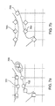
- this step 3-to-1 reduction 230 we choose one LDI in the block as the target LDI. We warp and resample the two remaining LDIs to the pixels of the target LDI.
- surfels 701-702 in Figure 7a are resampled to grid locations of sampling ray intersections 703-704 as shown in Figure 7b.
- the resampled surfels are stored in the reduced LDC tree 231.
- the reduction and resampling process degrades the quality of the surfel representation, both for shape and for shade.
- Resampled surfels from the same surface may have very different texture colors and normals 705.
- surfels from different surfaces may be closer than the threshold, which usually happens for thin structures. This may cause color and shading artifacts that are worsened during object motion. In practice, however, we did not encounter severe artifacts due to 3-to-1 reduction. Because our rendering pipeline handles LDCs and LDIs the same way, we can store blocks with thin structures as LDCs, while all other blocks can be reduced to single LDIs.
- the rendering pipeline 300 takes the surfel LDC tree 221 or the reduced LDC tree and renders it as an image 399 using hierarchical visibility culling and forward warping of blocks for a particular image plane orientation.
- Hierarchical rendering also allows us to estimate the number of projected surfels per output pixel. For maximum rendering efficiency, we project approximately one surfel per pixel and use the same resolution for the z-buffer as in the output image. For maximum image quality, we project multiple surfels per pixel, using a finer resolution of the z-buffer and high quality image reconstruction.
- d max is compared to the radius r 802 of the pixel reconstruction filter. If d max of the current block is larger than r , then its children are traversed. We project the block whose d max is smaller than r, then rendering approximately one surfel per pixel. The surfel density per pixel can be increased by choosing a smaller r, e.g., making r the diagonal of a subpixel.
- d max is stored with each projected surfel for subsequent use in the visibility splatting and the image reconstruction stages.
- Perspective projection, high z-buffer resolution, and magnification or zooming may lead to undersampling or "holes" in the z-buffer (depth buffer).
- a z-buffer pixel is defined as a hole when the pixel does not contain at least one corresponding visible surfel or background pixel projection.
- the holes have to be marked for image reconstruction. We call our novel marking approach visibility splatting. Image reconstruction is described below.
- Each pixel of the z-buffer stores a pointer to a nearest surfel, i.e., the surfel which has the smallest depth ( z ) value, and a current minimum depth value. Pixels are also marked as "holes," or not.
- the pixels of our z-buffer are initialized 951 with maximum depth values, e.g., "infinity" or a background scene, and no holes .
- Surfels depths are projected 952 to the z-buffer using nearest neighbor interpolation. Recall from Table B, the surfel depth is stored with each surfel.
- the z-buffer offers a good tradeoff between quality and speed, and our z-buffer can be integrated with traditional polygon graphics rendering methods, such as OpenGLTM.
- Depth values of the z-buffer pixels are only overwritten 953 if the depth value of the surfel ( s d ) is less than the depth value of the pixel (p d ). Thus, only surface features lying in front of other surface features are visible.
- tangential disks 501 are constructed for each surfel 502 in object space.
- the tangential disks form an ellipse 901 around the surfel.
- the bounding box parallelogram is scan-converted, and each z-buffer pixel is filled with the appropriate depth, depending on the surfel normal N 502. That is, if a depth value is less than a previously stored depth value, the stored depth value is overwritten.
- step 955 We use orthographic projection in step 955 for our visibility splatting to simplify the calculations.
- the direction of a minor axis a min 911 of the projected ellipse is parallel to the projection of the surfel normal N.
- a major axis a max 912 is orthogonal to a min .
- the length of the major axis is the projection of S max , which is approximated by d max 801 of Figure 8. This approximation takes the orientation and magnification of the LDC tree during projection into account.
- the short side of the bounding box is axis aligned with this coordinate axis to simplify scan conversion.
- the height h 914 of the bounding box is determined by intersecting the ellipse with the coordinate axis.
- the width w 915 of the bounding box is determined by projecting the vertex at the intersection of the major axis and the ellipse onto the x-axis.
- the values ⁇ z/ ⁇ x and ⁇ z/ ⁇ y are the partial derivatives of the surfel depth z with respect to the image x and y direction. These are constant because of the orthographic projection and can be calculated from the unit normal N. During scan conversion, the depth at each pixel inside the bounding box is calculated using the partial derivatives ⁇ z/ ⁇ x and ⁇ z/ ⁇ y . In addition, we add a small threshold ⁇ to each projected z value. The threshold ⁇ prevents the surfels that lie underneath the disk but still on the foreground surface from accidentally being discarded. In step 956, the depth values of the pixels ( p d ) are overwritten with the depth values of the projected tangential disk ( t d ) if t d ⁇ p d .
- our method for determining z-buffer depth values can also be used with polygons that are rasterized to pixels, with voxels, and other traditional point representations of objects. Our method can populate any z-buffer, independent of the underlying representation of the graphic object.
- each surfel in the LDC tree stores several prefiltered texture colors in the surfel texture mipmap.
- the surfel color is linearly interpolated from the surfel texture mipmap colors depending on the object minification and surface orientation.
- Figure 10a shows all visible surfels of a sampled surface projected to the z-buffer.
- the ellipses 1001 around the centers of the surfels mark the projection of the footprints of the highest resolution texture prefilter, as described above. Note that during prefiltering, we try to cover the entire surface with footprints.
- Figure 10b the number of samples per z-buffer pixel is limited to one by applying z-buffer depth tests. A surfel pointer in the z-buffer is replaced with another pointer when another closer surfel is located for the same pixel.
- the footprints of the remaining surfels have to be enlarged. If surfels are discarded in a given z-buffer pixel, then we can assume that the z-buffer pixels in the 3x3 neighborhood around the discarded pixels are not holes. Thus, the gaps can be filled when the texture footprint of each surfel covers at least the area of a z-buffer pixel. Consequently, the ellipse of the projected footprint has to have a minor radius of 2 s in the worst case, where s is the z-buffer pixel spacing. We ignore the worst case and use 2 2 s , implying that surfels are projected to z-buffer pixel centers.
- Figure 10b shows the scaled texture footprints 1002 as ellipses around projected surfels.
- a circle 1101 with radius 2 2 s is projected through an image space pixel onto a tangential plane 1102 of the surface from the direction of the view 1103, producing an ellipse 1104 in the tangent plane.
- the projection of the pixel is approximated with an orthographic projection.
- the major axis of the projected tangent space ellipse is used to determine the surfel mipmap level.
- the surfel color is determined by linear interpolation between the closest two mipmap levels. This is a linear interpolation between two samples, as opposed to interpolating eight samples as in tri-linear mipmapping.
- an illumination model is typically applied before visibility testing.
- deferred shading after visibility splatting according to the invention avoids unnecessary work.
- prior art particle shading is usually performed in object space to avoid transformation of normals to image space.
- Figures 12a-b show image reconstruction in the z-buffer according to the invention.
- the image (frame) buffer has the same resolution as the z-buffer.
- Surfels are mapped to pixel centers 1201 using nearest neighbor interpolation as shown with cross hatching.
- Holes 1202 are marked with a black X .
- each surfel stores d max as an estimate of the maximum distance between adjacent projected surfels of a block. This distance is a good estimate for the minimum radius of a pixel filter that contains at least one surfel.
- d max is a good estimate for the minimum radius of a pixel filter that contains at least one surfel.
- To interpolate the holes we can use, for example, a radially symmetric Gaussian filter with a radius slightly larger than d max positioned at hole pixel centers.
- a pull-push method as described by Gortler et al. in "The Lumigraph” Computer Graphics, SIGGRAPH Proceedings, pp. 43-54. August 1996.
- a high-quality alternative uses supersampling.
- an output image resolution is half, or some other fraction of the z-buffer resolution.
- Rendering for supersampling proceeds as before.
- image reconstruction we put a Gaussian filter at the centers of all output pixels to filter the subpixel colors.
- the radius of the filter is again d max to cover at least one surfel.
- the minimum radius is 2 2 s , where s is the sidelength of an output pixel.
- each surfel can be the same, or per surfel normal or texture derivatives can be used to scale the textures.
- each surfel could store an index into a table with brush type, orientation, and size. In contrast to Meier, we do texture splatting after visibility splatting.
- the color of an output pixel is determined for regular rendering and for supersampling in the absence of holes.
- the pixel color is determined by nearest neighbor interpolation from the closest visible surfel in the z-buffer.
- the color of that surfel is determined by linear interpolation between two surfel texture mipmap levels.
- the output pixel color is determined from two prefiltered texture samples.
- one output pixel contains the filtered colors of one surfel per z-buffer subpixel.
- up to eight prefiltered texture samples may contribute to an output pixel for 2x2 supersampling. This produces image quality similar to tri-linear mipmapping.
- a major advantage of our surfel rendering is that any kind of synthetic or scanned object can be converted to surfels. For example, we can sample volume data, point clouds, and LDIs of non-synthetic objects. Using an occlusion compatible traversal of the LDC tree, we enable order-independent transparency and true volume rendering.
- the hardware design of the surfel rendering pipeline is straightforward. Block warping involves only two conditionals for z-buffer tests. We do not need to perform clipping calculations. All frame buffer operations, such as visibility splatting and image reconstruction, can be implemented using standard rasterization and frame buffer techniques.
- Our rendering pipeline uses no inverse calculations, such as looking up textures from texture maps. Runtime texture filtering becomes simple with our pipeline. There is a high degree of data locality because shape and shade information can be loaded into the pipeline simultaneously with the surfel positional data. Consequently, caching will further improve performance.
- Our surfel rendering is ideal for organic models with very high shape and shade complexity. Because we do rasterization and texture filtering in the preprocessing stage, and not in the pipeline, the rendering cost per pixel is dramatically reduced. Rendering performance is essentially determined by warping, shading, and image reconstruction. These operations can easily exploit vectorization, parallelism, and pipelining. Our surfel rendering pipeline offers several speed-quality trade-offs. By decoupling image reconstruction and texture filtering, we achieve much higher image quality than comparable prior art point sample approaches. We introduce visibility splatting, which is very effective at detecting holes and increases image reconstruction performance. Antialiasing with supersampling is naturally integrated in our system. Our pipeline is capable of high image quality at interactive frame rates.
Landscapes
- Engineering & Computer Science (AREA)
- Computer Graphics (AREA)
- Physics & Mathematics (AREA)
- General Physics & Mathematics (AREA)
- Theoretical Computer Science (AREA)
- Image Generation (AREA)
- Image Processing (AREA)
Applications Claiming Priority (2)
| Application Number | Priority Date | Filing Date | Title |
|---|---|---|---|
| US514546 | 2000-02-28 | ||
| US09/514,546 US6583787B1 (en) | 2000-02-28 | 2000-02-28 | Rendering pipeline for surface elements |
Publications (2)
| Publication Number | Publication Date |
|---|---|
| EP1128328A2 true EP1128328A2 (fr) | 2001-08-29 |
| EP1128328A3 EP1128328A3 (fr) | 2003-11-12 |
Family
ID=24047661
Family Applications (1)
| Application Number | Title | Priority Date | Filing Date |
|---|---|---|---|
| EP01102241A Withdrawn EP1128328A3 (fr) | 2000-02-28 | 2001-01-31 | Pipeline de rendu des éléments de surface |
Country Status (3)
| Country | Link |
|---|---|
| US (1) | US6583787B1 (fr) |
| EP (1) | EP1128328A3 (fr) |
| JP (1) | JP4610105B2 (fr) |
Cited By (5)
| Publication number | Priority date | Publication date | Assignee | Title |
|---|---|---|---|---|
| EP1542167A1 (fr) * | 2003-12-09 | 2005-06-15 | Koninklijke Philips Electronics N.V. | Processeur informatique graphique et procédé de rendu des scènes 3D sur un écran d'affichage graphique 3D |
| GB2476552A (en) * | 2009-12-23 | 2011-06-29 | Intel Corp | Identifying pixels to be textured |
| WO2017220993A1 (fr) * | 2016-06-20 | 2017-12-28 | Flavourworks Ltd | Procédé et système de présentation d'une vidéo interactive |
| WO2019202207A1 (fr) * | 2018-04-19 | 2019-10-24 | Nokia Technologies Oy | Traitement de correctifs vidéo pour un contenu tridimensionnel |
| EP3610461A1 (fr) * | 2017-11-01 | 2020-02-19 | Google LLC | Tramage de texture d'image de profondeur en couches de haute qualité |
Families Citing this family (46)
| Publication number | Priority date | Publication date | Assignee | Title |
|---|---|---|---|---|
| US7023437B1 (en) * | 1998-07-22 | 2006-04-04 | Nvidia Corporation | System and method for accelerating graphics processing using a post-geometry data stream during multiple-pass rendering |
| US6993074B2 (en) * | 2000-03-24 | 2006-01-31 | Microsoft Corporation | Methods and arrangements for handling concentric mosaic image data |
| US6766281B1 (en) * | 2000-05-12 | 2004-07-20 | S3 Graphics Co., Ltd. | Matched texture filter design for rendering multi-rate data samples |
| GB0117157D0 (en) * | 2001-07-16 | 2001-09-05 | Imec Inter Uni Micro Electr | Extraction, hierarchical representation and flexible compression of surface meshes derived from 3D data |
| US7538764B2 (en) * | 2001-01-05 | 2009-05-26 | Interuniversitair Micro-Elektronica Centrum (Imec) | System and method to obtain surface structures of multi-dimensional objects, and to represent those surface structures for animation, transmission and display |
| US8166093B2 (en) * | 2001-02-08 | 2012-04-24 | Warner Music Group, Inc. | Method and apparatus for processing multimedia programs for play on incompatible devices |
| US7221381B2 (en) | 2001-05-09 | 2007-05-22 | Clairvoyante, Inc | Methods and systems for sub-pixel rendering with gamma adjustment |
| US7123277B2 (en) | 2001-05-09 | 2006-10-17 | Clairvoyante, Inc. | Conversion of a sub-pixel format data to another sub-pixel data format |
| US7492379B2 (en) * | 2002-01-07 | 2009-02-17 | Samsung Electronics Co., Ltd. | Color flat panel display sub-pixel arrangements and layouts for sub-pixel rendering with increased modulation transfer function response |
| US7417648B2 (en) | 2002-01-07 | 2008-08-26 | Samsung Electronics Co. Ltd., | Color flat panel display sub-pixel arrangements and layouts for sub-pixel rendering with split blue sub-pixels |
| AU2003228353A1 (en) | 2002-03-22 | 2003-10-13 | Michael F. Deering | Scalable high performance 3d graphics |
| US7525526B2 (en) * | 2003-10-28 | 2009-04-28 | Samsung Electronics Co., Ltd. | System and method for performing image reconstruction and subpixel rendering to effect scaling for multi-mode display |
| US7084923B2 (en) * | 2003-10-28 | 2006-08-01 | Clairvoyante, Inc | Display system having improved multiple modes for displaying image data from multiple input source formats |
| US7248268B2 (en) * | 2004-04-09 | 2007-07-24 | Clairvoyante, Inc | Subpixel rendering filters for high brightness subpixel layouts |
| US8149235B2 (en) * | 2004-08-20 | 2012-04-03 | Microsoft Corporation | System and method for upscaling low-resolution images |
| US9024949B2 (en) * | 2004-10-13 | 2015-05-05 | Sony Corporation | Object representation using distance functions |
| US20060177122A1 (en) * | 2005-02-07 | 2006-08-10 | Sony Computer Entertainment Inc. | Method and apparatus for particle manipulation using graphics processing |
| US7944443B1 (en) * | 2006-06-09 | 2011-05-17 | Pixar | Sliding patch deformer |
| US7876341B2 (en) * | 2006-08-28 | 2011-01-25 | Samsung Electronics Co., Ltd. | Subpixel layouts for high brightness displays and systems |
| US8018476B2 (en) | 2006-08-28 | 2011-09-13 | Samsung Electronics Co., Ltd. | Subpixel layouts for high brightness displays and systems |
| US9007388B1 (en) | 2006-09-28 | 2015-04-14 | Pixar | Caching attributes of surfaces without global parameterizations |
| US8189006B1 (en) * | 2006-09-28 | 2012-05-29 | Pixar | Caching attributes of surfaces without global parameterizations |
| US7990379B2 (en) * | 2006-10-25 | 2011-08-02 | Siemens Aktiengesellschaft | System and method for coronary segmentation and visualization |
| KR101288970B1 (ko) * | 2006-11-28 | 2013-07-24 | 삼성전자주식회사 | 렌더링 장치 및 방법 |
| JP4938093B2 (ja) * | 2007-03-23 | 2012-05-23 | トムソン ライセンシング | 2d−to−3d変換のための2d画像の領域分類のシステム及び方法 |
| WO2008137754A1 (fr) * | 2007-05-02 | 2008-11-13 | Survice Engineering Company | Graphe de scène haute performance par lancer de rayon |
| US8760450B2 (en) * | 2007-10-30 | 2014-06-24 | Advanced Micro Devices, Inc. | Real-time mesh simplification using the graphics processing unit |
| US8228327B2 (en) * | 2008-02-29 | 2012-07-24 | Disney Enterprises, Inc. | Non-linear depth rendering of stereoscopic animated images |
| US9336624B2 (en) * | 2008-10-07 | 2016-05-10 | Mitsubishi Electric Research Laboratories, Inc. | Method and system for rendering 3D distance fields |
| US9082216B2 (en) * | 2009-07-01 | 2015-07-14 | Disney Enterprises, Inc. | System and method for filter kernel interpolation for seamless mipmap filtering |
| US8725476B1 (en) * | 2010-05-04 | 2014-05-13 | Lucasfilm Entertainment Company Ltd. | Applying details in a simulation |
| US8970592B1 (en) | 2011-04-19 | 2015-03-03 | Lucasfilm Entertainment Company LLC | Simulating an arbitrary number of particles |
| US8780112B2 (en) | 2011-06-08 | 2014-07-15 | Pacific Data Images Llc | Coherent out-of-core point-based global illumination |
| US20130033507A1 (en) * | 2011-08-04 | 2013-02-07 | Nvidia Corporation | System, method, and computer program product for constructing an acceleration structure |
| US9196083B2 (en) * | 2012-01-16 | 2015-11-24 | Intel Corporation | Time-continuous collision detection using 3D rasterization |
| US9098941B2 (en) | 2012-01-23 | 2015-08-04 | Ayasdi, Inc. | Systems and methods for graphical layout |
| US8830254B2 (en) | 2012-01-24 | 2014-09-09 | Ayasdi, Inc. | Systems and methods for graph rendering |
| FR2988502A1 (fr) * | 2012-03-26 | 2013-09-27 | Thomson Licensing | Procede pour representer un milieu participant dans une scene et dispositif correspondant |
| US8957892B2 (en) | 2012-08-20 | 2015-02-17 | Disney Enterprises, Inc. | Stereo composition based on multiple camera rigs |
| US9852539B2 (en) * | 2015-02-26 | 2017-12-26 | Qualcomm Incorporated | Single pass surface splatting |
| KR101755206B1 (ko) * | 2016-04-29 | 2017-07-07 | 동국대학교 산학협력단 | 스케일러블 벡터 그래픽의 워핑 방법 |
| CN106210722B (zh) * | 2016-07-08 | 2019-06-25 | 上海大学 | 基于hevc的分层深度视频残差层数据的编码方法 |
| DE112016007098T5 (de) * | 2016-07-26 | 2019-04-18 | Hewlett-Packard Development Company, L.P. | Indexierung von voxeln für das 3d-drucken |
| CN108363569B (zh) * | 2018-03-07 | 2021-06-11 | 腾讯科技(深圳)有限公司 | 应用中的图像帧生成方法、装置、设备及存储介质 |
| US11561552B2 (en) * | 2020-09-15 | 2023-01-24 | Waymo Llc | Detecting environment changes using surfel data |
| CN113409436B (zh) * | 2021-06-02 | 2023-10-13 | 东北大学 | 一种菱形像素排列的体绘制方法 |
Family Cites Families (6)
| Publication number | Priority date | Publication date | Assignee | Title |
|---|---|---|---|---|
| US4694404A (en) * | 1984-01-12 | 1987-09-15 | Key Bank N.A. | High-speed image generation of complex solid objects using octree encoding |
| DE3650169T2 (de) * | 1985-06-05 | 1995-08-03 | Gen Electric | Anlage und Verfahren zur Anzeige von im Inneren eines Festkörpers eingeschlossenen Oberflächenstrukturen. |
| US5600763A (en) * | 1994-07-21 | 1997-02-04 | Apple Computer, Inc. | Error-bounded antialiased rendering of complex scenes |
| AU3718497A (en) * | 1996-06-28 | 1998-01-21 | Resolution Technologies, Inc. | Fly-through computer aided design method and apparatus |
| US6259452B1 (en) * | 1997-04-14 | 2001-07-10 | Massachusetts Institute Of Technology | Image drawing system and method with real-time occlusion culling |
| EP0890925A3 (fr) * | 1997-06-30 | 1999-03-31 | Sun Microsystems, Inc. | Système calculateur incluant un accélérateur graphique tri-dimensionnel avec capacités améliorées de mappage de texture |
-
2000
- 2000-02-28 US US09/514,546 patent/US6583787B1/en not_active Expired - Fee Related
-
2001
- 2001-01-31 EP EP01102241A patent/EP1128328A3/fr not_active Withdrawn
- 2001-02-27 JP JP2001052884A patent/JP4610105B2/ja not_active Expired - Fee Related
Cited By (9)
| Publication number | Priority date | Publication date | Assignee | Title |
|---|---|---|---|---|
| EP1542167A1 (fr) * | 2003-12-09 | 2005-06-15 | Koninklijke Philips Electronics N.V. | Processeur informatique graphique et procédé de rendu des scènes 3D sur un écran d'affichage graphique 3D |
| WO2005057501A1 (fr) * | 2003-12-09 | 2005-06-23 | Koninklijke Philips Electronics N.V. | Processeur d'infographie et procede permettant le rendu de scenes en 3d sur un ecran d'affichage d'images en 3d |
| GB2476552A (en) * | 2009-12-23 | 2011-06-29 | Intel Corp | Identifying pixels to be textured |
| GB2476552B (en) * | 2009-12-23 | 2013-12-25 | Intel Corp | Defining pixels to be textured |
| US9153064B2 (en) | 2009-12-23 | 2015-10-06 | Intel Corporation | Grouping pixels to be textured |
| WO2017220993A1 (fr) * | 2016-06-20 | 2017-12-28 | Flavourworks Ltd | Procédé et système de présentation d'une vidéo interactive |
| US11095956B2 (en) | 2016-06-20 | 2021-08-17 | Flavourworks Ltd | Method and system for delivering an interactive video |
| EP3610461A1 (fr) * | 2017-11-01 | 2020-02-19 | Google LLC | Tramage de texture d'image de profondeur en couches de haute qualité |
| WO2019202207A1 (fr) * | 2018-04-19 | 2019-10-24 | Nokia Technologies Oy | Traitement de correctifs vidéo pour un contenu tridimensionnel |
Also Published As
| Publication number | Publication date |
|---|---|
| JP4610105B2 (ja) | 2011-01-12 |
| US6583787B1 (en) | 2003-06-24 |
| JP2001283251A (ja) | 2001-10-12 |
| EP1128328A3 (fr) | 2003-11-12 |
Similar Documents
| Publication | Publication Date | Title |
|---|---|---|
| US6583787B1 (en) | Rendering pipeline for surface elements | |
| EP1128330B1 (fr) | Projection de visibilité et reconstruction d'image pour éléments de surface | |
| EP1128375B1 (fr) | Filtrage de texture pour éléments de surface | |
| EP1128331B1 (fr) | Structure de données hiérarchique pour éléments de surface | |
| Pfister et al. | Surfels: Surface elements as rendering primitives | |
| Meyer et al. | Interactive volumetric textures | |
| Lindstrom et al. | Image-driven simplification | |
| Szirmay‐Kalos et al. | Displacement Mapping on the GPU—State of the Art | |
| Sander et al. | Silhouette clipping | |
| Ofek et al. | Interactive reflections on curved objects | |
| Hirche et al. | Hardware Accelerated Per-Pixel Displacement Mapping. | |
| US7027046B2 (en) | Method, system, and computer program product for visibility culling of terrain | |
| EP1081656A2 (fr) | Méthode pour modeliser des objets graphiques interactivement | |
| Kaufman | Voxels as a computational representation of geometry | |
| Neyret | Synthesizing verdant landscapes using volumetric textures | |
| Decaudin et al. | Volumetric billboards | |
| Darsa et al. | Walkthroughs of complex environments using image-based simplification | |
| Moule et al. | Efficient bounded adaptive tessellation of displacement maps | |
| De Toledo et al. | Visualization of industrial structures with implicit gpu primitives | |
| Koo et al. | An efficient point rendering using octree and texture lookup | |
| Doggett et al. | Displacement mapping | |
| Lu et al. | Fast visualization of complex 3D models using displacement mapping | |
| Li et al. | Accurate Shadow Generation Analysis in Computer Graphics | |
| Meseth et al. | Interactive fragment tracing | |
| Chang et al. | View-independent object-space surface splatting |
Legal Events
| Date | Code | Title | Description |
|---|---|---|---|
| PUAI | Public reference made under article 153(3) epc to a published international application that has entered the european phase |
Free format text: ORIGINAL CODE: 0009012 |
|
| AK | Designated contracting states |
Kind code of ref document: A2 Designated state(s): AT BE CH CY DE DK ES FI FR GB GR IE IT LI LU MC NL PT SE TR |
|
| AX | Request for extension of the european patent |
Free format text: AL;LT;LV;MK;RO;SI |
|
| PUAL | Search report despatched |
Free format text: ORIGINAL CODE: 0009013 |
|
| AK | Designated contracting states |
Kind code of ref document: A3 Designated state(s): AT BE CH CY DE DK ES FI FR GB GR IE IT LI LU MC NL PT SE TR |
|
| AX | Request for extension of the european patent |
Extension state: AL LT LV MK RO SI |
|
| RIC1 | Information provided on ipc code assigned before grant |
Ipc: 7G 06T 17/00 B Ipc: 7G 06T 15/20 B Ipc: 7G 06T 1/20 A |
|
| AKX | Designation fees paid | ||
| REG | Reference to a national code |
Ref country code: DE Ref legal event code: 8566 |
|
| STAA | Information on the status of an ep patent application or granted ep patent |
Free format text: STATUS: THE APPLICATION IS DEEMED TO BE WITHDRAWN |
|
| 18D | Application deemed to be withdrawn |
Effective date: 20040513 |