EP1128432B1 - Fixation de modules à semi-conducteurs sur un dissipateur de chaleur - Google Patents
Fixation de modules à semi-conducteurs sur un dissipateur de chaleur Download PDFInfo
- Publication number
- EP1128432B1 EP1128432B1 EP01103358.6A EP01103358A EP1128432B1 EP 1128432 B1 EP1128432 B1 EP 1128432B1 EP 01103358 A EP01103358 A EP 01103358A EP 1128432 B1 EP1128432 B1 EP 1128432B1
- Authority
- EP
- European Patent Office
- Prior art keywords
- spring clip
- semiconductor module
- heat sink
- receptacle
- spring
- Prior art date
- Legal status (The legal status is an assumption and is not a legal conclusion. Google has not performed a legal analysis and makes no representation as to the accuracy of the status listed.)
- Expired - Lifetime
Links
Images

Classifications
-
- H—ELECTRICITY
- H10—SEMICONDUCTOR DEVICES; ELECTRIC SOLID-STATE DEVICES NOT OTHERWISE PROVIDED FOR
- H10W—GENERIC PACKAGES, INTERCONNECTIONS, CONNECTORS OR OTHER CONSTRUCTIONAL DETAILS OF DEVICES COVERED BY CLASS H10
- H10W40/00—Arrangements for thermal protection or thermal control
- H10W40/60—Securing means for detachable heating or cooling arrangements, e.g. clamps
- H10W40/641—Snap-on arrangements, e.g. clips
Definitions
- the invention relates to the attachment of semiconductor modules, in particular power semiconductor modules, for.
- semiconductor modules in particular power semiconductor modules, for.
- IGBT modules on a heat sink.
- power semiconductor modules are constructed such that electronic components are soldered to ceramic substrates, which are usually (optionally) soldered to a bottom plate that serves as a heat sink.
- the heat generated in the components must be dissipated safely. Since the optional base plate is usually not sufficient, the semiconductor module is usually flange-mounted with the substrate or base plate side to a heat sink or screwed with this.
- the EP0295387 discloses a device with semiconductor module and heat sink, which are connected by means of a spring clip.
- this invention has for its object to produce a cost-effective, simple and reliable connection between a semiconductor module and a heat sink.
- the semiconductor module by means of one or more clips of spring material, d. H. Spring clips, clamped to the heat sink.
- the heat sink can already have the desired shape as an extruded profile, which it requires to receive a clamp, without the need for additional post-processing of the heat sink.
- the connection is cheaper than a screw because the assembly can be done easier and faster.
- such a spring clip compensates for the setting amount between the heat sink and the semiconductor module with sufficient biasing distance, so that a reliable heat transfer without retightening or other installation steps necessary after the first operation or during operation can be ensured permanently.
- the clamps always ensure compliance with the desired clamping force. They have a simple shape and can be made of an elastic material, preferably spring steel.
- connection bracket and heat sink or semiconductor module can be made so that the clip can be inserted or locked and also automatically on / in the heat sink or semiconductor module holds when it is not in the tensioned state in which the semiconductor module by means of Spring clip is connected to the heat sink.
- the heat sink or the semiconductor module to a groove over the entire length or at least in the region of a spring clip receiving, in which the spring clip is attached to the heat sink or semiconductor module.
- the heat sink or the semiconductor module may also have a collar instead of a groove, via which a spring clip adapted thereto can be latched.
- the shape of the spring clip continues to be such that the semiconductor module or the heat sink engages itself without additional lateral forces by a single-directional assembly force.
- the housing of the semiconductor module already receives by casting at least one suitable basin for engaging the spring clip, which preferably has a curb, whereby the costs are not charged additionally.
- a spring clip can then preferably be automatically inserted into the basin, z. B. before the circuit board is soldered over it and would make it difficult to arrange the clip.
- a semiconductor module receives at least two tanks provided on opposite sides.
- several spring clips can be inserted into a basin or instead of a basin-shaped spring clip receiving a be provided differently shaped, z. B. a step-shaped. After placing the semiconductor module on the heat sink, the suitably shaped brackets with the aid of a tool, for. B.
- a spring clip adapted to this embodiment preferably has three bending edges, around which it wobbles during the latching process, and around the second and third one there arises a tension bend. An optional fourth bending edge can be clamped.
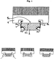
- the Fig. 1 shows in the upper part of a custom heat sink 1 with a matched semiconductor module attached thereto 2.
- the semiconductor module 2 is located with a plant side 2a at one provided for this purpose on the heat sink 1 support surface 1a on this and is clamped by two spring clips 4 to the heat sink 1.
- two open grooves are provided for this purpose as spring clip receptacles 3a, which, due to a broadening into the heat sink, allow a respective spring clip 4 to engage behind the heat sink 1 with respect to the pressure direction of the semiconductor module 2.
- a spring clip 4 has in each case one end region adapted to the respective spring clip receptacle 3a, which is hooked behind on a surface of the spring clip receptacle 3a which lies in a region of the spring clip receptacle 3a which partially underlays the bearing surface 1a of the cooling body 1 intended for the semiconductor module 2 ,
- the respective spring clip 4 hooks behind in the respective spring clip receptacle 3 a in such a way that it is held in a pulling direction perpendicular to the bearing surface 1 a of the heat sink 1.
- the semiconductor module 2 has a respective second spring clip receptacle 3d, on which the respective other side of a spring clip 4 engages such that the semiconductor module 2 held on the support surface 1a of the heat sink 1 and pressed against it.
- the second spring clip receptacle 3d advantageously consists of a shoulder provided on the side of the semiconductor module 2 opposite the contact surface 2 a of the semiconductor module 2, which is provided either only in the region provided for a respective spring clip 4 or over the entire length of the semiconductor module 2.
- a respective spring clip 4 is designed such that a force exerted by this force acts in a direction perpendicular to the support surface 1a of the heat sink 1.
- more than one spring clip 4 may be provided with respective first and second spring clip receptacles 3a and 3d, e.g. B. as in the in Fig. 1 Case shown two spring clips 4, which are respectively arranged at opposite edges of the support surface 1a of the heat sink 1.
- more than two spring clips 4 are provided, for. B. one on each free side of the semiconductor module 2, which is perpendicular to the contact side 2a of the semiconductor module 2.
- a semiconductor body 2 attached to a heat sink 1 is achieved.
- the semiconductor module 2 with its contact side 2a is applied to the support surface 1a of the heat sink 1 provided for this purpose, and the spring clips 4 are hooked on one side into the first clip receptacles 3a of the heat sink 1.
- a thermal compound and / or foil between the two contact surfaces can be given.
- the free sides of the spring clips 4 are passed through indicated by arrows latching operations, ie movement towards the semiconductor module 2 back, placed in the respective second spring clip recordings 3d. Due to the spring effect of the two spring clips 4, the semiconductor module 2 is connected to the heat sink 1 and pressed against this.
- the after mounting the spring clips 4 in the first spring clip receptacles 3a of the heat sink 1 free sides of the spring clips 4 are advantageously designed so that the spring clips 4 when snapped into the second Federklammeringn 3d of the semiconductor module 2 is not spread, ie with the Einrastkraft additional lateral forces be charged.
- the lower right figure in the Fig. 1 shows the also in the upper picture the Fig. 1 shown final state after assembly, ie after the engagement of the spring clips 4 on the semiconductor module. 2
- Such a mounting is also possible with a semiconductor module 2 already mounted on a printed circuit board with the side facing away from the heat sink 1.
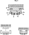
- the Fig. 2 shows a second example.
- the semiconductor module 2 also in the Fig. 1 Not shown connecting legs on the plant side 2a opposite side shown.
- the first spring clip receptacle 3a of the heat sink 1 is not provided as the support surface 1a partially undercut groove in the heat sink 1, but open to the respect to the support surface 1a for the semiconductor module 2 perpendicular sides of the heat sink 1, whereby the spring clips 4 not as in the first in the Fig. 1 shown embodiment of obliquely coming from below must be mounted in the first spring clip receptacle 3a, but are pushed laterally from a direction perpendicular to the intended for the semiconductor module 2 support surface can.
- FIG. 1 shows second example clip spring 3d of the semiconductor module 2 has the advantage of a simplified assembly, as shown in the lower part of the Fig. 2 is shown.
- the lower left picture of the Fig. 2 shows that initially in a first step, the heat sink 1 is placed with its bearing surface 1a on the contact side 2a of the semiconductor module 2, after which the two spring clips 4 are inserted in a second step by laterally sliding into the respective first and second spring clip receptacles 3a, 3d, in order to obtain the assembled state shown on the lower right, which is also in the upper part of the Fig. 2 is shown.
- thermal paste and / or foil may also be applied between the two contact surfaces of the heat sink 1 and the semiconductor module 2 in the second example.
- the spring clips 4 are advantageously designed so that they do not have to be stopped extra when pushed.
- connection spring clip and heat sink takes place so that the clip automatically holds on / in the heat sink 1, whereby an even easier handling is guaranteed.
- a collar over its entire length provided over a formed in the end region thickening a spring clip 4 can be used so that it automatically holds on the heat sink.
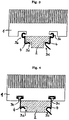
- the functionality and mounting of the semiconductor module 2 on the heat sink 1 corresponds to the first embodiment according to the invention, wherein the spring clips 4 for attachment of the semiconductor module either apart first have to be bent in order to allow application of the heat sink 1 to the semiconductor module 2, as in a in the Fig. 3 Fed spring 4 shown on the left, or must be configured so that they bend apart automatically when plugging the heat sink 1 on the semiconductor module 2, as in a in the Fig. 3 Right shown spring clip 4 is the case.
- the spring clips 4 due to their design, either by simply releasing or by automatic snapping automatically engage in the second spring clip recording 3d of the semiconductor module 2 and hold the semiconductor module 2 to the heat sink 1 and press it.
- the fourth example differs from the third only to the effect that a spring clip 4 can not be attached to a collar-shaped first spring clip receptacle 3b, but on a groove-shaped first spring clip receptacle 3c on the heat sink that it automatically holds in the heat sink.
- the first spring clip receptacle 3 c has a groove located in the heat sink 1, which extends into the heat sink 1 in z. B. widened paragraph, so that a suitably adapted spring clip 4 can be used there so that it automatically holds in the heat sink.
- the assembly of the equipped with at least one spring clip 4 heatsink 1 to a semiconductor module is done according to the in the Fig. 3 shown third embodiment of the invention.
- spring clips 4 or spring clip receptacles 3a, 3b, 3c, 3d can be combined with each other, so that provided on the semiconductor module 2 spring clip receptacles 3b or 3c with a collar or a groove could be.
- a spring clip receptacle 3a, 3b, 3c, 3d extends either over a complete side of the heat sink 1 or the semiconductor module 2 or over a partial area thereof.
- a respective spring clip 4 can also be manufactured in one piece with the heat sink 1 or the semiconductor module 2.
- the spring clips described above relate their cohesive body 1 and the semiconductor module 2 cohesive spring force either from at least one of their latching in a respective spring clip receiving end, as shown in the Fig. 1 . 3 and 4 is shown, or from the intermediate middle area, as in the Fig. 2 is shown.
- spring clips are conceivable.
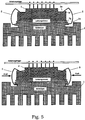
- the Fig. 5 shows an embodiment of the invention. Unlike the one in the Fig. 1
- the second spring clip receptacle 3d of the semiconductor module 2, which has a stepped design is designed as a basin-shaped spring clip receptacle 3e, which has a curb 3f on the outer edge of the semiconductor module 2.
- This embodiment has the advantage of lateral positioning through the walls of the basin and increased retention of a spring clip in the spring clip receptacle by the curb 3f both in the relaxed state before the spring clip connects the semiconductor module 2 to the heat sink 1, as well as in this tensioned or mounted state ,
- the heat sink 1, and in particular the first spring clip receiving 3a corresponds to the first.
- spring clip 5 results in a simplified assembly, as shown in the Fig. 5 is shown.
- the elastic starting material in the Fig. 6 shown spring clip 5 according to the invention has in principle a rectangular shape and is converted by several steps in the specially designed spring clip 5 with a smooth end face 5a, four bending edges 5b - 5e, a clip sheet 5f and a curved end surface 5g.
- the straight end surface 5a is adapted in size to a designated support surface of the basin-shaped spring clip receptacle 3e.
- the smooth end surface 5a is followed by a first bending edge 5b, in which the starting material of the specially designed spring clip 5 is bent upwards at an obtuse angle.
- the angle is to be chosen so that the specially designed spring clip 5 neither in the assembled state, ie in the relaxed state before the spring clip connects the semiconductor module 2 to the heat sink 1, still in the cocked or mounted state rests against the curb 3f the basin-shaped spring clip recording, here about 140 ° to 150 °.
- the starting material is bent downwards at a second bending edge 5 c at an angle of approximately 90 ° in order to extend in its length to a distance between the basin-shaped spring clip receptacle 3 e of the semiconductor module and step-shaped spring clip receiving 3a of the heat sink 1 adapted bracket sheet 5f to pass.
- the starting material at a third bending edge 5c is bent at an angle of about 90 ° up to the smooth end surface 5a, before passing a fourth bending edge 5d with a tight bend of about 180 ° into a bent end portion 5g ends.
- clip sheet 5f forms together with the between the first bending edge 5b and the second bending edge 5c lying portion, the second bending edge 5c and the third bending edge 5d a clamping arc, which biases the semiconductor module 2 in the mounted state to the heat sink 1.
- the upper picture of the Fig. 5 shows that first in a first step, the semiconductor module 2 is mounted with a mounted circuit carrier and two inserted specially designed spring clips 5 head-high, ie with upward pointing circuit carrier, with its investment side 2a on the support surface 1a of the heat sink 1.
- the bent end 5g faces a tooth 3g of the respective first spring clip receptacles 3a with a small distance. The distance serves to avoid touching the specially designed spring clips 5 with the first spring clip receptacle 3 a of the heat sink 1, which could occur on lowering the semiconductor module 2 on the heat sink 1 due to possible inaccuracies of the mounting device, thus an unwanted adjustment of the clip from its initial position is prevented.
- the length of the section of the specially designed spring clip 5 lying between the first bending edge 5b and the second bending edge 5c is determined by the distance required here.
- the two specially designed spring clips 5 in a second step by applying a lateral force and thereby causing rocking of the specially designed spring clip 5 about its first bending edge 5b with its curved end face 5g via the tooth 3g in the respective first spring clip receptacles 3a locked into place in the Fig. 5 to obtain the assembled state shown below.
- the curb 3f supports that the specially designed spring clip 5 does not slip out of the normally provided with a smooth surface basin-shaped spring clip receptacle 3e of the semiconductor module 2.
- the specially configured spring clip 5 Due to its shape, the specially configured spring clip 5 has the functionality of rocking around the first bending edge 5 b when the force is applied. Next arises around the second bending edge 5c and third bending edge 5d with intervening clamp sheet 5f a clamping arc and at the fourth bending edge 5e together with the bent end piece 5g, the clamping takes place.
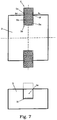
- the specially designed spring clip 5 is usually placed in a basin-shaped spring clip receptacle 3e of the semiconductor module 2, as well as in the upper half of Fig. 7 is shown in a plan view, wherein the basin-shaped spring clip receptacle 3e has walls that can also go beyond the body of the semiconductor module 2, as indicated by dashed lines in the lower half of Fig. 7 is shown, the specially designed spring clip 5 is preferably made narrower around the first bending edge 5b and the second bending edge 5c. As a result, it receives a firm hold between the walls and can rock around the first bending edge 5b in the lateral force action and absorb the clamping force at this point.
- the clip sheet 5f can also have a convex shape in the installed state or a smooth shape, with the buckling or bending angles at the bending edges having to be adapted accordingly.
- heat-conducting paste and / or foil can also be applied between the two contact surfaces of the heat sink 1 and the semiconductor module 2 in the invention.
Landscapes
- Cooling Or The Like Of Semiconductors Or Solid State Devices (AREA)
- Cooling Or The Like Of Electrical Apparatus (AREA)
Claims (4)
- Dispositif comprenant un module à semi-conducteurs (2), un corps de refroidissement (1) et une pince élastique (5) avec une surface d'extrémité courbe, le module à semi-conducteurs (2) présentant au moins un premier logement de pince élastique (3e) pour recevoir à chaque fois une pince élastique (5) qui retient le module à semi-conducteurs (2) sur le corps de refroidissement (1), et
le premier logement de pince élastique (3e) présentant une arête de bord (3f) au niveau du côté extérieur du module à semi-conducteurs (2), laquelle retient une extrémité de la pince élastique (5) au moins dans l'état serré dans lequel le module à semi-conducteurs (2) est connecté au corps de refroidissement (1) au moyen de la pince élastique (5),
caractérisé en ce que
la pince élastique (5) présente une surface d'extrémité lisse (5a), quatre arêtes de flexion (5b, 5c, 5d, 5e) et une partie courbe de pince (5f), la surface d'extrémité lisse (5a) ayant une dimension adaptée au logement de pince élastique (3e) . - Dispositif selon la revendication 1,
caractérisé en ce que
deux deuxièmes logements de pince élastique (3a) sont prévus au niveau du corps de refroidissement (1) . - Dispositif selon la revendication 2,
caractérisé en ce que
la pince élastique (5) présente :- au moins une portion adaptée au premier logement de pince élastique respectif (3e) du module à semi-conducteurs (2) et/ou au deuxième logement de pince élastique respectif (3a) du corps de refroidissement (1) pour l'encliquetage dans le premier et/ou le deuxième logement de pince élastique (3e ; 3a) au moins dans l'état serré, dans lequel le module à semi-conducteurs (2) est connecté au moyen de la pince élastique (5) au corps de refroidissement (1), et- une surface d'extrémité lisse (5a) adaptée au premier logement de pince élastique (3e) de telle sorte que la pince élastique (5) insérée dans le premier logement de pince élastique (3e) soit suspendue librement au module à semi-conducteurs et ne puisse pas tomber de celui-ci. - Dispositif selon la revendication 3,
caractérisé par
une première arête de flexion (5b), autour de laquelle bascule la pince élastique (5) lors d'une opération d'encliquetage, ainsi qu'une deuxième arête de flexion (5c) et une troisième arête de flexion entre lesquelles est formée une partie courbe de serrage au moyen de laquelle la force de pressage souhaitée du module à semi-conducteurs (2) contre le corps de refroidissement (1) peut être ajustée.
Applications Claiming Priority (2)
| Application Number | Priority Date | Filing Date | Title |
|---|---|---|---|
| DE10008571 | 2000-02-24 | ||
| DE10008571 | 2000-02-24 |
Publications (3)
| Publication Number | Publication Date |
|---|---|
| EP1128432A2 EP1128432A2 (fr) | 2001-08-29 |
| EP1128432A3 EP1128432A3 (fr) | 2003-10-01 |
| EP1128432B1 true EP1128432B1 (fr) | 2016-04-06 |
Family
ID=7632193
Family Applications (1)
| Application Number | Title | Priority Date | Filing Date |
|---|---|---|---|
| EP01103358.6A Expired - Lifetime EP1128432B1 (fr) | 2000-02-24 | 2001-02-13 | Fixation de modules à semi-conducteurs sur un dissipateur de chaleur |
Country Status (4)
| Country | Link |
|---|---|
| US (1) | US6431259B2 (fr) |
| EP (1) | EP1128432B1 (fr) |
| JP (1) | JP3455729B2 (fr) |
| CN (1) | CN1204796C (fr) |
Families Citing this family (62)
| Publication number | Priority date | Publication date | Assignee | Title |
|---|---|---|---|---|
| DE20115922U1 (de) * | 2001-01-11 | 2002-02-21 | Siemens AG, 80333 München | Kunststoff-Schaltplatte eines hydraulischen Kraftfahrzeug-Getriebesteuergerätes |
| US7145254B2 (en) * | 2001-07-26 | 2006-12-05 | Denso Corporation | Transfer-molded power device and method for manufacturing transfer-molded power device |
| US6545352B1 (en) | 2002-02-15 | 2003-04-08 | Ericsson Inc. | Assembly for mounting power semiconductive modules to heat dissipators |
| US6758692B2 (en) * | 2002-07-08 | 2004-07-06 | Hon Hai Precision Ind. Co., Ltd. | Heat sink assembly having retention module |
| US6639803B1 (en) | 2002-07-11 | 2003-10-28 | International Business Machines Corporation | Compliant heat sink device/mounting system interconnect and a method of implementing same |
| US6633485B1 (en) * | 2002-11-20 | 2003-10-14 | Illinois Tool Works Inc. | Snap-in heat sink for semiconductor mounting |
| DE10314221A1 (de) * | 2003-03-28 | 2004-10-21 | eupec Europäische Gesellschaft für Leistungshalbleiter mbH | Halbleitermodul sowie Vorrichtung zum lösbaren Befestigen eines Halbleitermoduls auf einem Träger |
| DE10316356B4 (de) * | 2003-04-10 | 2012-07-26 | Semikron Elektronik Gmbh & Co. Kg | Modular aufgebautes Leistungshalbleitermodul |
| US6864573B2 (en) * | 2003-05-06 | 2005-03-08 | Daimlerchrysler Corporation | Two piece heat sink and device package |
| DE10326458B4 (de) * | 2003-06-12 | 2006-05-04 | Phoenix Contact Gmbh & Co. Kg | Kühlanordnung für elektronische Bauelemente |
| US7824368B2 (en) * | 2003-06-19 | 2010-11-02 | Ethicon Endo-Surgery, Inc. | Method for endoscopic, transgastric access into the abdominal cavity |
| US6765798B1 (en) | 2003-06-19 | 2004-07-20 | Curtiss-Wright Controls, Inc. | Electronic thermal management utilizing device with deflectable, two-leg conductive member; and with elastic, thermally-conductive material there between |
| US6856511B1 (en) * | 2003-07-17 | 2005-02-15 | Cisco Technology, Inc. | Methods and apparatus for attaching a heat sink to a circuit board component |
| US7139174B1 (en) * | 2003-10-29 | 2006-11-21 | Cisco Technology, Inc. | Techniques for attaching a heat sink assembly to a circuit board component |
| TWM246689U (en) * | 2003-10-31 | 2004-10-11 | Hon Hai Prec Ind Co Ltd | Heat dissipation assembly |
| JP4154325B2 (ja) * | 2003-12-19 | 2008-09-24 | 株式会社日立産機システム | 電気回路モジュール |
| DE102004021122B4 (de) * | 2004-04-29 | 2007-10-11 | Semikron Elektronik Gmbh & Co. Kg | Anordnung in Druckkontaktierung mit einem Leistungshalbleitermodul |
| US7113406B1 (en) | 2004-07-22 | 2006-09-26 | Cisco Technology, Inc. | Methods and apparatus for fastening a set of heatsinks to a circuit board |
| US20060180926A1 (en) * | 2005-02-11 | 2006-08-17 | Rambus, Inc. | Heat spreader clamping mechanism for semiconductor modules |
| US20060225866A1 (en) * | 2005-04-07 | 2006-10-12 | Chao-Chuan Chen | Cooling fin assembly |
| DE102005032814A1 (de) * | 2005-07-12 | 2007-01-18 | Behr Gmbh & Co. Kg | Kühlvorrichtung, insbesondere für ein elektronisches Steuergerät |
| TWI305573B (en) * | 2006-08-14 | 2009-01-21 | Delta Electronics Inc | Heat sink |
| US9237685B2 (en) | 2006-08-18 | 2016-01-12 | Delphi Technologies, Inc. | Lightweight audio system for automotive applications and method |
| US7733659B2 (en) | 2006-08-18 | 2010-06-08 | Delphi Technologies, Inc. | Lightweight audio system for automotive applications and method |
| JPWO2008099554A1 (ja) * | 2007-02-15 | 2010-05-27 | 日本電気株式会社 | 半導体パッケージの実装構造 |
| US7950446B2 (en) * | 2007-07-16 | 2011-05-31 | Fu Zhun Precision Industry (Shen Zhen) Co., Ltd. | Heat dissipation device with clip for mounting a fan to a heat sink thereof |
| US8102045B2 (en) * | 2007-08-08 | 2012-01-24 | Infineon Technologies Ag | Integrated circuit with galvanically bonded heat sink |
| DE102008038421B4 (de) * | 2007-08-25 | 2015-07-30 | Sew-Eurodrive Gmbh & Co Kg | Verfahren zum Betreiben eines elektrischen Geräts |
| US20090165997A1 (en) * | 2007-12-27 | 2009-07-02 | Hon Hai Precision Industry Co., Ltd. | Heat sink |
| CN101616570B (zh) * | 2008-06-25 | 2012-07-04 | 富准精密工业(深圳)有限公司 | 保护盖 |
| WO2010099415A1 (fr) | 2009-02-27 | 2010-09-02 | Delphi Technologies, Inc. | Système audio léger pour applications automobiles et procédé |
| US8526800B2 (en) * | 2009-12-18 | 2013-09-03 | Whirlpool Corporation | Glass-ceramic cooktop and method of assembling the same |
| JP4942825B2 (ja) * | 2010-01-18 | 2012-05-30 | 三菱電機株式会社 | 制御装置一体型回転電機 |
| US20110277978A1 (en) * | 2010-05-11 | 2011-11-17 | Chun-Po Lai | Snap-fit type heat sink module |
| DE102010022968A1 (de) | 2010-06-08 | 2011-12-08 | A. Raymond Et Cie S.C.S. | Vorrichtung zum thermoelektrischen Erzeugen von elektrischer Energie |
| JP5609596B2 (ja) * | 2010-12-01 | 2014-10-22 | アイシン・エィ・ダブリュ株式会社 | 熱源素子と熱伝導性部材との固定構造、及び熱源素子と熱伝導性部材との固定方法 |
| US9591788B2 (en) | 2011-04-13 | 2017-03-07 | Siemens Aktiengesellschaft | Coupling system between a waste-heat generator and a waste-heat receiver |
| EP2512210B1 (fr) * | 2011-04-13 | 2019-03-06 | Siemens Aktiengesellschaft | Système de couplage entre un émetteur de chaleur d'échappement et un récepteur de chaleur d'échappement |
| JP5529208B2 (ja) * | 2011-08-25 | 2014-06-25 | トヨタ自動車株式会社 | パワーモジュールの構造及び成形方法 |
| KR101228841B1 (ko) * | 2011-10-04 | 2013-02-04 | 엘에스산전 주식회사 | 일체형 탄성클립을 이용한 전력용반도체 고정장치 |
| US9103601B2 (en) * | 2012-05-11 | 2015-08-11 | Asia Vital Components Co., Ltd. | Heat dissipation device assembly structure |
| US20130308274A1 (en) * | 2012-05-21 | 2013-11-21 | Triquint Semiconductor, Inc. | Thermal spreader having graduated thermal expansion parameters |
| BR112015008465B1 (pt) | 2012-10-19 | 2021-07-20 | Interdigital Ce Patent Holdings | Dispositivo eletrônico de acoplamento a dissipador de calor |
| DE102013104949B3 (de) * | 2013-05-14 | 2014-04-24 | Semikron Elektronik Gmbh & Co. Kg | Leistungselektronische Schalteinrichtung und Anordnung hiermit |
| CN103545274B (zh) * | 2013-06-28 | 2017-08-01 | 青岛美奂电子科技有限公司 | 散热卡子固定结构以及用于拆装该散热卡子的工具 |
| CN104682670B (zh) * | 2013-11-26 | 2017-12-12 | 台达电子企业管理(上海)有限公司 | 电源转换装置与其电源转换板组件 |
| JP6182474B2 (ja) * | 2014-02-13 | 2017-08-16 | オムロンオートモーティブエレクトロニクス株式会社 | 電子部品の固定構造および固定方法 |
| US10192846B2 (en) | 2014-11-05 | 2019-01-29 | Infineon Technologies Austria Ag | Method of inserting an electronic component into a slot in a circuit board |
| US10553557B2 (en) * | 2014-11-05 | 2020-02-04 | Infineon Technologies Austria Ag | Electronic component, system and method |
| US10064287B2 (en) | 2014-11-05 | 2018-08-28 | Infineon Technologies Austria Ag | System and method of providing a semiconductor carrier and redistribution structure |
| US9674990B2 (en) * | 2015-01-23 | 2017-06-06 | Rockwell Automation Technoloies, Inc. | Devices and methods for cooling bus capacitors |
| US9851108B2 (en) | 2015-04-23 | 2017-12-26 | Whirlpool Corporation | Snap spring clip for burner unit mounting |
| KR102028017B1 (ko) * | 2016-08-24 | 2019-10-02 | 주식회사 엘지화학 | 열전 모듈 패키징 장치 |
| KR102052709B1 (ko) * | 2016-09-26 | 2019-12-05 | 주식회사 엘지화학 | 열전 모듈 교환 가능한 패키징 장치 |
| DE102018207033B3 (de) * | 2018-05-07 | 2019-07-04 | Siemens Aktiengesellschaft | Anordnung elektrischer Module, Stromrichter und Luftfahrzeug mit einer derartigen Anordnung sowie Verfahren zur Herstellung der Anordnung |
| US10672684B2 (en) * | 2018-10-08 | 2020-06-02 | Cisco Technology, Inc. | Heat sink hold down system for direct attachment to printed circuit board |
| KR102767456B1 (ko) | 2018-11-05 | 2025-02-17 | 삼성전자주식회사 | 솔리드 스테이트 드라이브 장치 및 이를 포함하는 컴퓨터 서버 시스템 |
| JP7215194B2 (ja) * | 2019-01-30 | 2023-01-31 | 富士電機株式会社 | スナバ装置および電力変換装置 |
| WO2020215042A1 (fr) * | 2019-04-19 | 2020-10-22 | Edward Stoneham | Dissipateur thermique à compression |
| CN113113330A (zh) * | 2021-03-15 | 2021-07-13 | 杭州沃镭智能科技股份有限公司 | 一种igbt功率模块封装设备 |
| CN216114775U (zh) * | 2021-09-15 | 2022-03-22 | 厦门优佰仕电子科技有限公司 | 一种可调式冷热器 |
| DE102024129427A1 (de) * | 2024-10-11 | 2026-04-16 | Infineon Technologies Ag | Halbleiterpackage mit einer Befestigungsvorrichtung zum Befestigen des Halbleiterpackages an einem Kühlkörper |
Family Cites Families (19)
| Publication number | Priority date | Publication date | Assignee | Title |
|---|---|---|---|---|
| US4716494A (en) * | 1986-11-07 | 1987-12-29 | Amp Incorporated | Retention system for removable heat sink |
| US4878108A (en) * | 1987-06-15 | 1989-10-31 | International Business Machines Corporation | Heat dissipation package for integrated circuits |
| GB2240425B (en) * | 1990-01-20 | 1994-01-12 | Motorola Ltd | Radio transmitter power amplifier with cooling apparatus |
| US5099550A (en) | 1990-11-05 | 1992-03-31 | Mi Proprietary | Clamp for attachment of a heat sink |
| US5357404A (en) * | 1991-11-18 | 1994-10-18 | The Whitaker Corporation | EMI shield, and assembly using same |
| US5304735A (en) * | 1992-02-14 | 1994-04-19 | Aavid Engineering, Inc. | Heat sink for an electronic pin grid array |
| EP0619605B1 (fr) | 1993-04-05 | 1996-08-28 | STMicroelectronics S.r.l. | Combinaison d'un dispositif semi-conducteur électronique et un refroidisseur |
| US5464054A (en) * | 1993-08-09 | 1995-11-07 | Thermalloy, Inc. | Spring clamp and heat sink assembly |
| DE4335299A1 (de) * | 1993-10-15 | 1995-04-20 | Siemens Ag | Kühlkörper mit integrierter Befestigung |
| US5371652A (en) * | 1993-11-15 | 1994-12-06 | Thermalloy, Inc. | Spring clamp assembly with electrically insulating shoe |
| JPH07183435A (ja) | 1993-12-24 | 1995-07-21 | Nec Corp | 電子部品用ヒートシンク |
| US5343362A (en) * | 1994-01-07 | 1994-08-30 | Zytec Corporation | Heat sink assembly |
| US5436798A (en) * | 1994-01-21 | 1995-07-25 | Wakefield Engineering, Inc. | Spring clip and heat sink assembly for electronic components |
| US5621244A (en) * | 1994-05-16 | 1997-04-15 | Lin; Shih-Jen | Fin assembly for an integrated circuit |
| DE9410061U1 (de) * | 1994-06-21 | 1994-09-01 | Lin, Shih-Jen, Taipeh/T'ai-pei | Kühlkörperanordnung für eine integrierte Schaltung |
| US5804875A (en) * | 1996-12-10 | 1998-09-08 | Dell Computer Corporation | Computer system with heat sink having an integrated grounding tab |
| US5977622A (en) * | 1997-04-25 | 1999-11-02 | Lsi Logic Corporation | Stiffener with slots for clip-on heat sink attachment |
| US5909358A (en) * | 1997-11-26 | 1999-06-01 | Todd Engineering Sales, Inc. | Snap-lock heat sink clip |
| DE29817502U1 (de) * | 1998-09-30 | 1999-01-28 | Asia Vital Components Co., Ltd., Hsin-Chuang, Taipeh | Haltevorrichtung zum Befestigen eines Kühlkörpers auf einer Zentraleinheit |
-
2001
- 2001-02-13 EP EP01103358.6A patent/EP1128432B1/fr not_active Expired - Lifetime
- 2001-02-21 JP JP2001045281A patent/JP3455729B2/ja not_active Expired - Fee Related
- 2001-02-24 CN CNB01116512XA patent/CN1204796C/zh not_active Expired - Fee Related
- 2001-02-26 US US09/793,352 patent/US6431259B2/en not_active Expired - Lifetime
Also Published As
| Publication number | Publication date |
|---|---|
| JP2001244393A (ja) | 2001-09-07 |
| JP3455729B2 (ja) | 2003-10-14 |
| EP1128432A3 (fr) | 2003-10-01 |
| EP1128432A2 (fr) | 2001-08-29 |
| US20010030037A1 (en) | 2001-10-18 |
| CN1204796C (zh) | 2005-06-01 |
| CN1316876A (zh) | 2001-10-10 |
| US6431259B2 (en) | 2002-08-13 |
Similar Documents
| Publication | Publication Date | Title |
|---|---|---|
| EP1128432A2 (fr) | Fixation de modules à semi-conducteurs sur un dissipateur de chaleur | |
| EP2789931B1 (fr) | Dispositif de maintien pour la fixation d'un module de surface sur un support | |
| DE69632865T2 (de) | Transistor-lötclip und kühlkörper | |
| DE69011929T2 (de) | Führungsanordnung für Gegenstände, wie Leiterplatten. | |
| EP2495507A1 (fr) | Elément de fixation pour cadres de module solaire | |
| WO2010124680A2 (fr) | Dispositif pour la fixation d'un rail porteur sur un crochet de toiture | |
| DE102009002992A1 (de) | Leistungshalbleitermodulanordnung mit verdrehsicher auf einem Kühlkörper montierbarem Leistungshalbleitermodul | |
| EP3120421B1 (fr) | Borne de connexion électrique | |
| EP1929160B1 (fr) | Bride de fixation | |
| EP2249102A2 (fr) | Connecteur pour un rail de profilé | |
| WO2003107418A1 (fr) | Dissipateur thermique | |
| EP3623722A1 (fr) | Crochet de toit | |
| EP2206147B1 (fr) | Pince de fixation | |
| AT409070B (de) | Vorrichtung zum befestigen der frontblende einer schublade | |
| DE10236550B4 (de) | Haltevorrichtung für ein Leitungsstrang-Schuhelement | |
| DE19916010C1 (de) | Anordnung zur Wärmeableitung von einem elektrischen Bauelement auf einer Leiterplatte zu einem Kühlkörper | |
| DE2128812A1 (de) | Federnder Klemmverbinder | |
| DE69928444T2 (de) | Zusammendrückbare elektrische leitungen für substratkontakt | |
| EP1795799B1 (fr) | Luminaire avec une platine support maintenue dans son espace intérieur | |
| DE3118415A1 (de) | U-foermige metallklammer | |
| DE102006019256A1 (de) | Befestigungsvorrichtung | |
| DE69920364T2 (de) | Vorrichtung zum mechanischen sperren eines elektronischen bauteils auf einem substrat | |
| EP0931882B1 (fr) | Dispositif de fixation d'un appareil encastré, par exemple un évier, dans une planche de support échancrée | |
| DE9310630U1 (de) | An einer Montagefläche befestigtes elektrisches Gerät | |
| DE19524047C2 (de) | Vorrichtung zum Sichern einer einen Gegenstand an einen Grundkörper pressenden Klammer |
Legal Events
| Date | Code | Title | Description |
|---|---|---|---|
| PUAI | Public reference made under article 153(3) epc to a published international application that has entered the european phase |
Free format text: ORIGINAL CODE: 0009012 |
|
| AK | Designated contracting states |
Kind code of ref document: A2 Designated state(s): AT BE CH CY DE DK ES FI FR GB GR IE IT LI LU MC NL PT SE TR |
|
| AX | Request for extension of the european patent |
Free format text: AL;LT;LV;MK;RO;SI |
|
| PUAL | Search report despatched |
Free format text: ORIGINAL CODE: 0009013 |
|
| AK | Designated contracting states |
Kind code of ref document: A3 Designated state(s): AT BE CH CY DE DK ES FI FR GB GR IE IT LI LU MC NL PT SE TR |
|
| AX | Request for extension of the european patent |
Extension state: AL LT LV MK RO SI |
|
| 17P | Request for examination filed |
Effective date: 20040312 |
|
| 17Q | First examination report despatched |
Effective date: 20040415 |
|
| AKX | Designation fees paid |
Designated state(s): DE |
|
| GRAP | Despatch of communication of intention to grant a patent |
Free format text: ORIGINAL CODE: EPIDOSNIGR1 |
|
| INTG | Intention to grant announced |
Effective date: 20150813 |
|
| GRAS | Grant fee paid |
Free format text: ORIGINAL CODE: EPIDOSNIGR3 |
|
| GRAA | (expected) grant |
Free format text: ORIGINAL CODE: 0009210 |
|
| RAP1 | Party data changed (applicant data changed or rights of an application transferred) |
Owner name: INFINEON TECHNOLOGIES AG |
|
| AK | Designated contracting states |
Kind code of ref document: B1 Designated state(s): DE |
|
| REG | Reference to a national code |
Ref country code: DE Ref legal event code: R096 Ref document number: 50116545 Country of ref document: DE |
|
| REG | Reference to a national code |
Ref country code: DE Ref legal event code: R097 Ref document number: 50116545 Country of ref document: DE |
|
| PLBE | No opposition filed within time limit |
Free format text: ORIGINAL CODE: 0009261 |
|
| STAA | Information on the status of an ep patent application or granted ep patent |
Free format text: STATUS: NO OPPOSITION FILED WITHIN TIME LIMIT |
|
| 26N | No opposition filed |
Effective date: 20170110 |
|
| PGFP | Annual fee paid to national office [announced via postgrant information from national office to epo] |
Ref country code: DE Payment date: 20190426 Year of fee payment: 19 |
|
| REG | Reference to a national code |
Ref country code: DE Ref legal event code: R119 Ref document number: 50116545 Country of ref document: DE |
|
| PG25 | Lapsed in a contracting state [announced via postgrant information from national office to epo] |
Ref country code: DE Free format text: LAPSE BECAUSE OF NON-PAYMENT OF DUE FEES Effective date: 20200901 |