EP1128448A2 - Circuit de commande électrique de moteurs piézoélectriques - Google Patents
Circuit de commande électrique de moteurs piézoélectriques Download PDFInfo
- Publication number
- EP1128448A2 EP1128448A2 EP01200563A EP01200563A EP1128448A2 EP 1128448 A2 EP1128448 A2 EP 1128448A2 EP 01200563 A EP01200563 A EP 01200563A EP 01200563 A EP01200563 A EP 01200563A EP 1128448 A2 EP1128448 A2 EP 1128448A2
- Authority
- EP
- European Patent Office
- Prior art keywords
- circuit
- piezoelectric drive
- phase detector
- input
- output signal
- Prior art date
- Legal status (The legal status is an assumption and is not a legal conclusion. Google has not performed a legal analysis and makes no representation as to the accuracy of the status listed.)
- Granted
Links
Images

Classifications
-
- H—ELECTRICITY
- H02—GENERATION; CONVERSION OR DISTRIBUTION OF ELECTRIC POWER
- H02N—ELECTRIC MACHINES NOT OTHERWISE PROVIDED FOR
- H02N2/00—Electric machines in general using piezoelectric effect, electrostriction or magnetostriction
-
- B—PERFORMING OPERATIONS; TRANSPORTING
- B26—HAND CUTTING TOOLS; CUTTING; SEVERING
- B26B—HAND-HELD CUTTING TOOLS NOT OTHERWISE PROVIDED FOR
- B26B19/00—Clippers or shavers operating with a plurality of cutting edges, e.g. hair clippers, dry shavers
- B26B19/28—Drive layout for hair clippers or dry shavers, e.g. providing for electromotive drive
- B26B19/282—Motors without a rotating central drive shaft, e.g. linear motors
-
- H—ELECTRICITY
- H02—GENERATION; CONVERSION OR DISTRIBUTION OF ELECTRIC POWER
- H02N—ELECTRIC MACHINES NOT OTHERWISE PROVIDED FOR
- H02N2/00—Electric machines in general using piezoelectric effect, electrostriction or magnetostriction
- H02N2/0005—Electric machines in general using piezoelectric effect, electrostriction or magnetostriction producing non-specific motion; Details common to machines covered by H02N2/02 - H02N2/16
- H02N2/0075—Electrical details, e.g. drive or control circuits or methods
- H02N2/008—Means for controlling vibration frequency or phase, e.g. for resonance tracking
Definitions
- the invention relates to a circuit for the control of a piezoelectric Drive.
- piezoelectric drives requires an AC voltage to operate at a certain frequency. This frequency must have the desired resonance of the piezoelectric Activate the drive. The optimal drive frequency is close to the mechanical resonance frequency of the piezoelectric drive.
- Such an electrical Circuit for driving piezoelectric drives is in the patent US-A 5013982. It's about operating a piezoelectric drive, especially a traveling wave motor with two AC voltages applied. The electrical circuit used is used to control the frequency and Phase angle of the drive voltage of the piezoelectric drive. With that the Drive speed regulated.
- a simple and inexpensive electrical circuit to be implemented Control of the piezoelectric drive can be created that is straightforward different piezoelectric drives must be adapted.
- an output signal of a first Measuring circuit is present at a first input of a phase detector that an output signal a logic circuit or an output signal of a second measuring circuit on one second input of the phase detector is present that a second output signal of the logic circuit is present as an input signal at an output stage, which is provided for the Piezoelectric drive to supply an AC voltage that a loop filter the output signal of the phase detector is processed and an actuating signal to a voltage-controlled Outputs oscillator, which is its output signal at the input of the logic circuit provides and that a delay element is provided, the frequency of the optimal Working point and efficiency of the controlled piezoelectric drive adjust.
- a measuring circuit according to claim 2 is provided. This measurement circuit enables the phase zero crossings and thus the phase position of the voltage at a Detect sensor electrode on the piezoelectric resonator.
- a measuring circuit according to claim 3 is provided. This measurement circuit enables the phase zero crossings and thus the phase position of the current through the to detect piezoelectric drive in a different way.
- the embodiment according to claim 4 has a cheaper but reliable Detection of the phase position of the current by the piezoelectric drive is an advantage.
- Here can be on the operational amplifier necessary in the embodiment according to claim 3 to be dispensed with.
- the configuration according to claim 5 also enables detection of the Phase position of the current through the piezoelectric drive through two anti-parallel ones Diodes.
- An embodiment of the second measuring circuit is provided in claim 6. This Measuring circuit enables the phase zero crossings and thus the phase position of the to detect voltage applied to the piezoelectric drive.
- the configurations according to claims 7 and 8 allow the control loop determined operating point (frequency offset) with respect to the resonance frequency of the piezoelectric To specify the drive. Both realizations of a built-in delay are technically equivalent.
- the delay element ensures the setting of the optimum Working point, which is at a frequency slightly next to the resonance frequency of the piezoelectric Drive lies.
- the location of the resonance frequency of the piezoelectric drive can by the location of the phase zero crossing the voltage of the first measuring circuit regarding the position of the phase zero crossing of the output voltage of the logic circuit or the position of the phase zero crossing that applied to the piezoelectric drive Tension can be found.
- the Phase difference between the two for detecting the resonance frequency of the piezoelectric Shift signals used drive can be found.
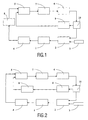
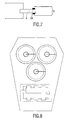
- the piezoelectric drive 1 is equipped with an output stage 2 with the necessary Voltage and electrical power supplied, the output stage 2 from a DC voltage source 3 such as a battery or a rechargeable battery. Also included the circuits a measuring circuit 4 for detecting the phase of the current through the piezoelectric drive 1 or for detecting the phase of a measuring voltage on a special sensor electrode 14 on the piezoelectric drive 1 as shown in Figure 7. Electrodes 14 are attached to the surface of the piezoelectric drive 1, which give off a tension. This tension is with a not shown here Operational amplifier prepared for the control loop.
- the measuring circuit 4 in FIGS. 4 to 6 shown in more detail.
- a measuring impedance 12 as in FIG. 4 can be used.
- the Measuring impedance 12 is connected in series with the piezoelectric drive 1. Since the Measurement impedance 12, in order to avoid electrical losses, must be very low-resistance, the voltage applied across the measuring impedance 12 also does not change here Operational amplifier shown amplified and to the one input of the phase detector 5th spent.
- the second measuring circuit according to FIG. 5 contains a Zener diode 11, which is in series with the piezoelectric drive 1. Since the diode 11 only from one is permeable to certain applied voltage, the phase zero crossings can also be hereby made determine.
- the voltage across the Zener diode 11 is also one Input of the phase detector 5 supplied. Since no operational amplifier is necessary here this solution is particularly inexpensive.
- Another way through the phase of the current To determine the piezoelectric drive 1, the measuring circuit according to FIG. 6 is included an anti-parallel connection of diodes 15. The current flows through this anti-parallel connection and creates a voltage drop. This small voltage drop will via a differential amplifier, in the simple case again an operational amplifier, the first input of the phase detector 5 supplied.
- phase of the current through the piezoelectric drive 1 thus measured can be combined with the phase of the applied voltage of the piezoelectric detected via a measuring circuit (13)
- Drive 1 can be fed directly to a phase detector 5.
- the voltage of the piezoelectric drive 1 is not fed directly to the phase detector 5, but the output voltage present at an output of a logic circuit 10 is tapped.
- the phase difference to the actual phase of the voltage applied must piezoelectric drive 1 depending on the frequency, the drive load and the concrete designs of the circuit are taken into account and corrected.
- Task of Logic circuit 10 is to a bridge circuit, not shown here, in the output stage 2 control with which the applied voltage of the piezoelectric drive 1 with respect Amplitude and frequency can be changed.
- the output of the phase detector 5 is processed in a control loop of a loop filter 7.
- the loop filter 7 consists of passive components such as resistors and Capacities, the poles and zeros of the transfer function of the loop Filters 7 must be adapted to the respective circuit.
- the exit of the loop Filters 7 in turn controls the voltage-controlled oscillator 6 and the itself subsequent logic circuit 10.
- a delay element 8 This can be as in Figure 1 between the measuring circuit 4 and the first input of the phase detector 5 or as in Figure 2 in the branch between the one output of the logic circuit 10, a frequency divider that may be present 9 and the second input of the phase detector 5.
- 3 is the delay element 8 between the second Measuring circuit 13 and the second input of the phase detector 5.
- the delay element 8 ensures the desired, set deviation from the phase zero crossing. This deviation has proven to be the working point for optimal efficiency of the proven piezoelectric drive 1.
- the power amplifier 2 In order to avoid harmonic distortion of harmonics, it makes sense to use the power amplifier 2 with a multiple, in particular 6 times, in relation to the frequency of the drive 1, operate at a higher frequency. In this case there is in the coupling branch between the one Output of the logic circuit 10 and the second input of the phase detector 5 To provide frequency divider 9. If the power amplifier 2 with the normal working frequency of Operated piezoelectric drive 1, the frequency divider 9 is not required.
Landscapes
- Life Sciences & Earth Sciences (AREA)
- Forests & Forestry (AREA)
- Engineering & Computer Science (AREA)
- Mechanical Engineering (AREA)
- General Electrical Machinery Utilizing Piezoelectricity, Electrostriction Or Magnetostriction (AREA)
- Electrical Control Of Air Or Fuel Supplied To Internal-Combustion Engine (AREA)
- Ultra Sonic Daignosis Equipment (AREA)
- Apparatuses For Generation Of Mechanical Vibrations (AREA)
Applications Claiming Priority (2)
| Application Number | Priority Date | Filing Date | Title |
|---|---|---|---|
| DE10008937A DE10008937A1 (de) | 2000-02-25 | 2000-02-25 | Elektrischer Schaltkreis zur Ansteuerung von piezoelektrischen Antrieben |
| DE10008937 | 2000-02-25 |
Publications (3)
| Publication Number | Publication Date |
|---|---|
| EP1128448A2 true EP1128448A2 (fr) | 2001-08-29 |
| EP1128448A3 EP1128448A3 (fr) | 2005-06-15 |
| EP1128448B1 EP1128448B1 (fr) | 2006-11-29 |
Family
ID=7632426
Family Applications (1)
| Application Number | Title | Priority Date | Filing Date |
|---|---|---|---|
| EP01200563A Expired - Lifetime EP1128448B1 (fr) | 2000-02-25 | 2001-02-19 | Circuit de commande électrique de moteurs piézoélectriques |
Country Status (8)
| Country | Link |
|---|---|
| US (1) | US6396192B2 (fr) |
| EP (1) | EP1128448B1 (fr) |
| JP (1) | JP2001251873A (fr) |
| KR (1) | KR20010085594A (fr) |
| CN (1) | CN1218464C (fr) |
| AT (1) | ATE347177T1 (fr) |
| DE (2) | DE10008937A1 (fr) |
| IL (1) | IL141584A (fr) |
Families Citing this family (14)
| Publication number | Priority date | Publication date | Assignee | Title |
|---|---|---|---|---|
| KR100536753B1 (ko) * | 2001-11-19 | 2005-12-14 | (주)피에조테크놀리지 | 피엘엘방식을 이용한 초음파 모터 구동방법 |
| DE10158584A1 (de) | 2001-11-29 | 2003-07-03 | Philips Intellectual Property | Piezoelektrische Antriebsvorrichtung und ein Regelverfahren für eine piezoelektrische Antriebsvorrichtung |
| DE10218565A1 (de) * | 2002-04-26 | 2003-11-06 | Philips Intellectual Property | Startprozess-Steuerung für den Anlauf eines Piezomotors |
| GB2398534B (en) * | 2003-02-19 | 2005-11-16 | Gillette Co | Safety razors |
| GB2399045B (en) * | 2003-02-19 | 2005-11-16 | Gillette Co | Safety razors |
| CN100468943C (zh) * | 2004-03-31 | 2009-03-11 | 中国科学院电子学研究所 | 压电执行器驱动电源 |
| JP4209806B2 (ja) * | 2004-04-27 | 2009-01-14 | ティーオーエー株式会社 | 共鳴周波数検出方法、共鳴周波数選択方法、および、共鳴周波数検出装置 |
| KR100705004B1 (ko) * | 2005-07-11 | 2007-04-09 | 삼성전기주식회사 | 피에조 액추에이터 구동 회로 |
| KR100703205B1 (ko) * | 2005-11-07 | 2007-04-06 | 삼성전기주식회사 | 압전 초음파 모터의 구동 제어 장치 |
| KR100714550B1 (ko) * | 2005-12-09 | 2007-05-07 | 삼성전기주식회사 | 전기활성 폴리머 액츄에이터의 구동 장치 |
| KR100932323B1 (ko) * | 2006-11-30 | 2009-12-16 | 헬스 앤드 라이프 컴퍼니 리미티드 | 압전 발생 시스템 및 발생 방법 |
| EP3090845A1 (fr) * | 2015-05-08 | 2016-11-09 | Braun GmbH | Procédé pour régler la température de refroidissement maximale d'un élément de refroidissement d'un appareil électrique utilisateur et un tel appareil |
| DE102015220291B4 (de) * | 2015-10-19 | 2022-01-05 | Robert Bosch Gmbh | Mikroelektromechanisches System und Steuerverfahren |
| CN106707760B (zh) * | 2017-02-17 | 2020-02-14 | 南京理工大学 | 一种用于压电驱动器动态迟滞补偿的非线性逆控制方法 |
Family Cites Families (16)
| Publication number | Priority date | Publication date | Assignee | Title |
|---|---|---|---|---|
| GB2183371B (en) * | 1985-10-09 | 1989-09-27 | Canon Kk | Vibration wave motor and drive circuit therefor |
| US4713571A (en) * | 1986-01-23 | 1987-12-15 | Canon Kabushiki Kaisha | Driving circuit of a vibration wave motor |
| US4794294A (en) * | 1986-06-12 | 1988-12-27 | Canon Kabushiki Kaisha | Vibration wave motor |
| US4879528A (en) * | 1988-08-30 | 1989-11-07 | Olympus Optical Co., Ltd. | Ultrasonic oscillation circuit |
| US5013982A (en) | 1989-05-02 | 1991-05-07 | Olympus Optical Co., Ltd. | Circuit for driving ultrasonic motor |
| US6005328A (en) * | 1989-06-15 | 1999-12-21 | Nikon Corporation | Driving device and method for ultrasonic wave motor |
| JPH03112379A (ja) * | 1989-09-21 | 1991-05-13 | Matsushita Electric Ind Co Ltd | 超音波モータの駆動回路 |
| US5113116A (en) * | 1989-10-05 | 1992-05-12 | Firma J. Eberspacher | Circuit arrangement for accurately and effectively driving an ultrasonic transducer |
| JP2995789B2 (ja) * | 1990-03-15 | 1999-12-27 | 株式会社ニコン | 超音波モータの駆動装置 |
| JPH04200282A (ja) * | 1990-11-29 | 1992-07-21 | Nikon Corp | 超音波モータの駆動装置 |
| US5233274A (en) * | 1990-11-30 | 1993-08-03 | Asmo Co., Ltd. | Drive circuit for langevin type ultrasonic bolt-tightening motor |
| US5130619A (en) * | 1990-12-26 | 1992-07-14 | Kubota Corporation | Drive control apparatus for an ultrasonic motor |
| US5563478A (en) * | 1992-08-18 | 1996-10-08 | Nikon Corporation | Drive control device for an ultrasonic motor |
| DE4412900C2 (de) * | 1994-04-14 | 2000-04-27 | Eberspaecher J Gmbh & Co | Verfahren und Vorrichtung zum Feststellen des Einsetzens einer Überflutung eines Ultraschallzerstäubers |
| US6154095A (en) * | 1997-02-27 | 2000-11-28 | Seiko Epson Corporation | Phase locked loop clock source provided with a plurality of frequency adjustments |
| DE19757139A1 (de) * | 1997-12-20 | 1999-06-24 | Philips Patentverwaltung | Antriebsvorrichtung für wenigstens zwei Rotationselemente mit wenigstens einem piezoelektrischen Antriebselement |
-
2000
- 2000-02-25 DE DE10008937A patent/DE10008937A1/de not_active Withdrawn
-
2001
- 2001-02-19 DE DE50111514T patent/DE50111514D1/de not_active Expired - Fee Related
- 2001-02-19 AT AT01200563T patent/ATE347177T1/de not_active IP Right Cessation
- 2001-02-19 EP EP01200563A patent/EP1128448B1/fr not_active Expired - Lifetime
- 2001-02-21 CN CN011028858A patent/CN1218464C/zh not_active Expired - Fee Related
- 2001-02-22 IL IL14158401A patent/IL141584A/en not_active IP Right Cessation
- 2001-02-22 JP JP2001046160A patent/JP2001251873A/ja not_active Withdrawn
- 2001-02-22 US US09/790,200 patent/US6396192B2/en not_active Expired - Fee Related
- 2001-02-26 KR KR1020010009620A patent/KR20010085594A/ko not_active Withdrawn
Also Published As
| Publication number | Publication date |
|---|---|
| US20010043025A1 (en) | 2001-11-22 |
| JP2001251873A (ja) | 2001-09-14 |
| US6396192B2 (en) | 2002-05-28 |
| ATE347177T1 (de) | 2006-12-15 |
| EP1128448A3 (fr) | 2005-06-15 |
| EP1128448B1 (fr) | 2006-11-29 |
| IL141584A0 (en) | 2002-03-10 |
| DE10008937A1 (de) | 2001-08-30 |
| IL141584A (en) | 2004-08-31 |
| CN1218464C (zh) | 2005-09-07 |
| KR20010085594A (ko) | 2001-09-07 |
| DE50111514D1 (de) | 2007-01-11 |
| CN1310513A (zh) | 2001-08-29 |
Similar Documents
| Publication | Publication Date | Title |
|---|---|---|
| EP1128448A2 (fr) | Circuit de commande électrique de moteurs piézoélectriques | |
| DE69025031T2 (de) | Antriebsvorrichtung für Ultraschallmotor | |
| EP1017159B1 (fr) | Méthode de régulation d'un moteur électrique monophasé ou polyphasé commandé par un convertisseur tension/fréquence | |
| DE3835090C2 (fr) | ||
| EP2559094B1 (fr) | Batterie à équilibrage d'éléments | |
| DE102007040552A1 (de) | PWM-Verfahren für Direktumrichter | |
| WO2012016735A1 (fr) | Convertisseur d'énergie destiné à fournir de l'énergie électrique | |
| EP3763026A1 (fr) | Procédé pour faire fonctionner un système d'entraînement électrique comprenant un accumulateur d'énergie et système d'entraînement pour l'exécution d'un tel procédé | |
| DE2847208C2 (de) | Ansteuerschaltung für ein schwingungsfähiges elektromechanisches System | |
| DE102013224586A1 (de) | Frequenzerzeugung für einen Resonanzwandler | |
| EP4387862A1 (fr) | Ensemble circuit et procédé d'alimentation électrique | |
| DE69029711T2 (de) | Schaltungsanordnung zur Steuerung eines Freikolbenmotors, insbesondere eines Kühlschrankkompressors | |
| EP2979311A1 (fr) | Agencement de circuit et procédé d'excitation d'un transformateur piézoélectrique | |
| DE102006017369A1 (de) | Elektrohandwerkzeugmaschine mit Ausschaltverzögerungsvorrichtung | |
| DE102019105103A1 (de) | Entladungsgenerator | |
| WO1998043266A1 (fr) | Mecanisme de commande electromagnetique | |
| DE19753210A1 (de) | Wiederaufladbare elektrische Stromquelle | |
| DE102019209769A1 (de) | Überwachung einer elektrischen Maschine hinsichtlich des Vorliegens eines Fehlerfalls | |
| DE102022207987A1 (de) | Entladung eines Hochvolt-Kondensators | |
| EP1197285A2 (fr) | Circuit électrique pour generer des impulsions de démarrage de l'arc pour le soudage à l'arc | |
| DD231883B1 (de) | Einrichtung zur messung von gleichstroemen | |
| DE19702007B4 (de) | Hochfrequenz-Leistungsgenerator | |
| WO2012016734A1 (fr) | Convertisseur d'énergie multiphase destiné à fournir de l'énergie électrique | |
| DE102023106666A1 (de) | Anordnung für eine elektrische Maschine | |
| DE3332652A1 (de) | Stromdetektor |
Legal Events
| Date | Code | Title | Description |
|---|---|---|---|
| PUAI | Public reference made under article 153(3) epc to a published international application that has entered the european phase |
Free format text: ORIGINAL CODE: 0009012 |
|
| AK | Designated contracting states |
Kind code of ref document: A2 Designated state(s): AT BE CH CY DE DK ES FI FR GB GR IE IT LI LU MC NL PT SE TR |
|
| AX | Request for extension of the european patent |
Free format text: AL;LT;LV;MK;RO;SI |
|
| RAP1 | Party data changed (applicant data changed or rights of an application transferred) |
Owner name: PHILIPS CORPORATE INTELLECTUAL PROPERTY GMBH Owner name: KONINKLIJKE PHILIPS ELECTRONICS N.V. |
|
| RAP1 | Party data changed (applicant data changed or rights of an application transferred) |
Owner name: KONINKLIJKE PHILIPS ELECTRONICS N.V. Owner name: PHILIPS INTELLECTUAL PROPERTY & STANDARDS GMBH |
|
| PUAL | Search report despatched |
Free format text: ORIGINAL CODE: 0009013 |
|
| AK | Designated contracting states |
Kind code of ref document: A3 Designated state(s): AT BE CH CY DE DK ES FI FR GB GR IE IT LI LU MC NL PT SE TR |
|
| AX | Request for extension of the european patent |
Extension state: AL LT LV MK RO SI |
|
| 17P | Request for examination filed |
Effective date: 20051215 |
|
| AKX | Designation fees paid |
Designated state(s): AT BE CH CY DE DK ES FI FR GB GR IE IT LI LU MC NL PT SE TR |
|
| GRAP | Despatch of communication of intention to grant a patent |
Free format text: ORIGINAL CODE: EPIDOSNIGR1 |
|
| RIN1 | Information on inventor provided before grant (corrected) |
Inventor name: REICHINGER, CHRISTIAN, DR.,PHILIPS CORP. INTEL. Inventor name: MORALES SERRANO, FRANCISCO, DR. |
|
| GRAS | Grant fee paid |
Free format text: ORIGINAL CODE: EPIDOSNIGR3 |
|
| GRAA | (expected) grant |
Free format text: ORIGINAL CODE: 0009210 |
|
| AK | Designated contracting states |
Kind code of ref document: B1 Designated state(s): AT DE ES FR GB IT NL |
|
| PG25 | Lapsed in a contracting state [announced via postgrant information from national office to epo] |
Ref country code: IT Free format text: LAPSE BECAUSE OF FAILURE TO SUBMIT A TRANSLATION OF THE DESCRIPTION OR TO PAY THE FEE WITHIN THE PRESCRIBED TIME-LIMIT;WARNING: LAPSES OF ITALIAN PATENTS WITH EFFECTIVE DATE BEFORE 2007 MAY HAVE OCCURRED AT ANY TIME BEFORE 2007. THE CORRECT EFFECTIVE DATE MAY BE DIFFERENT FROM THE ONE RECORDED. Effective date: 20061129 Ref country code: NL Free format text: LAPSE BECAUSE OF FAILURE TO SUBMIT A TRANSLATION OF THE DESCRIPTION OR TO PAY THE FEE WITHIN THE PRESCRIBED TIME-LIMIT Effective date: 20061129 |
|
| RBV | Designated contracting states (corrected) |
Designated state(s): AT DE ES FR GB IT NL |
|
| REG | Reference to a national code |
Ref country code: GB Ref legal event code: FG4D Free format text: NOT ENGLISH |
|
| REF | Corresponds to: |
Ref document number: 50111514 Country of ref document: DE Date of ref document: 20070111 Kind code of ref document: P |
|
| GBT | Gb: translation of ep patent filed (gb section 77(6)(a)/1977) |
Effective date: 20070214 |
|
| PG25 | Lapsed in a contracting state [announced via postgrant information from national office to epo] |
Ref country code: ES Free format text: LAPSE BECAUSE OF FAILURE TO SUBMIT A TRANSLATION OF THE DESCRIPTION OR TO PAY THE FEE WITHIN THE PRESCRIBED TIME-LIMIT Effective date: 20070312 |
|
| NLV1 | Nl: lapsed or annulled due to failure to fulfill the requirements of art. 29p and 29m of the patents act | ||
| ET | Fr: translation filed | ||
| PLBE | No opposition filed within time limit |
Free format text: ORIGINAL CODE: 0009261 |
|
| STAA | Information on the status of an ep patent application or granted ep patent |
Free format text: STATUS: NO OPPOSITION FILED WITHIN TIME LIMIT |
|
| 26N | No opposition filed |
Effective date: 20070830 |
|
| PG25 | Lapsed in a contracting state [announced via postgrant information from national office to epo] |
Ref country code: AT Free format text: LAPSE BECAUSE OF NON-PAYMENT OF DUE FEES Effective date: 20070219 |
|
| PGFP | Annual fee paid to national office [announced via postgrant information from national office to epo] |
Ref country code: GB Payment date: 20090302 Year of fee payment: 9 |
|
| PGFP | Annual fee paid to national office [announced via postgrant information from national office to epo] |
Ref country code: DE Payment date: 20090430 Year of fee payment: 9 |
|
| PGFP | Annual fee paid to national office [announced via postgrant information from national office to epo] |
Ref country code: FR Payment date: 20090227 Year of fee payment: 9 |
|
| GBPC | Gb: european patent ceased through non-payment of renewal fee |
Effective date: 20100219 |
|
| REG | Reference to a national code |
Ref country code: FR Ref legal event code: ST Effective date: 20101029 |
|
| PG25 | Lapsed in a contracting state [announced via postgrant information from national office to epo] |
Ref country code: FR Free format text: LAPSE BECAUSE OF NON-PAYMENT OF DUE FEES Effective date: 20100301 |
|
| PG25 | Lapsed in a contracting state [announced via postgrant information from national office to epo] |
Ref country code: DE Free format text: LAPSE BECAUSE OF NON-PAYMENT OF DUE FEES Effective date: 20100901 |
|
| PG25 | Lapsed in a contracting state [announced via postgrant information from national office to epo] |
Ref country code: GB Free format text: LAPSE BECAUSE OF NON-PAYMENT OF DUE FEES Effective date: 20100219 |