EP1128482A2 - Enceinte de protection pour connexions de câble électrique multiconducteur - Google Patents
Enceinte de protection pour connexions de câble électrique multiconducteur Download PDFInfo
- Publication number
- EP1128482A2 EP1128482A2 EP01102849A EP01102849A EP1128482A2 EP 1128482 A2 EP1128482 A2 EP 1128482A2 EP 01102849 A EP01102849 A EP 01102849A EP 01102849 A EP01102849 A EP 01102849A EP 1128482 A2 EP1128482 A2 EP 1128482A2
- Authority
- EP
- European Patent Office
- Prior art keywords
- cable
- shells
- protective enclosure
- motor
- terminals
- Prior art date
- Legal status (The legal status is an assumption and is not a legal conclusion. Google has not performed a legal analysis and makes no representation as to the accuracy of the status listed.)
- Withdrawn
Links
- 230000001681 protective effect Effects 0.000 title claims abstract description 34
- NFLLKCVHYJRNRH-UHFFFAOYSA-N 8-chloro-1,3-dimethyl-7H-purine-2,6-dione 2-(diphenylmethyl)oxy-N,N-dimethylethanamine Chemical compound O=C1N(C)C(=O)N(C)C2=C1NC(Cl)=N2.C=1C=CC=CC=1C(OCCN(C)C)C1=CC=CC=C1 NFLLKCVHYJRNRH-UHFFFAOYSA-N 0.000 claims abstract description 15
- 229920003023 plastic Polymers 0.000 claims description 9
- 239000004033 plastic Substances 0.000 claims description 9
- 238000004804 winding Methods 0.000 claims description 8
- 238000000465 moulding Methods 0.000 claims description 7
- 238000004873 anchoring Methods 0.000 claims description 6
- 238000000605 extraction Methods 0.000 claims description 4
- 239000000463 material Substances 0.000 claims description 4
- 230000000295 complement effect Effects 0.000 claims 1
- 238000002788 crimping Methods 0.000 description 6
- 239000004020 conductor Substances 0.000 description 5
- 238000000034 method Methods 0.000 description 3
- 238000004519 manufacturing process Methods 0.000 description 2
- 230000008878 coupling Effects 0.000 description 1
- 238000010168 coupling process Methods 0.000 description 1
- 238000005859 coupling reaction Methods 0.000 description 1
- 238000003780 insertion Methods 0.000 description 1
- 230000037431 insertion Effects 0.000 description 1
- 239000011810 insulating material Substances 0.000 description 1
- 238000009413 insulation Methods 0.000 description 1
- 230000000670 limiting effect Effects 0.000 description 1
- 230000013011 mating Effects 0.000 description 1
- 239000002184 metal Substances 0.000 description 1
- 238000003825 pressing Methods 0.000 description 1
- 238000005476 soldering Methods 0.000 description 1
Images


Classifications
-
- H—ELECTRICITY
- H01—ELECTRIC ELEMENTS
- H01R—ELECTRICALLY-CONDUCTIVE CONNECTIONS; STRUCTURAL ASSOCIATIONS OF A PLURALITY OF MUTUALLY-INSULATED ELECTRICAL CONNECTING ELEMENTS; COUPLING DEVICES; CURRENT COLLECTORS
- H01R13/00—Details of coupling devices of the kinds covered by groups H01R12/70 or H01R24/00 - H01R33/00
- H01R13/46—Bases; Cases
- H01R13/50—Bases; Cases formed as an integral body
- H01R13/501—Bases; Cases formed as an integral body comprising an integral hinge or a frangible part
-
- H—ELECTRICITY
- H01—ELECTRIC ELEMENTS
- H01R—ELECTRICALLY-CONDUCTIVE CONNECTIONS; STRUCTURAL ASSOCIATIONS OF A PLURALITY OF MUTUALLY-INSULATED ELECTRICAL CONNECTING ELEMENTS; COUPLING DEVICES; CURRENT COLLECTORS
- H01R13/00—Details of coupling devices of the kinds covered by groups H01R12/70 or H01R24/00 - H01R33/00
- H01R13/58—Means for relieving strain on wire connection, e.g. cord grip, for avoiding loosening of connections between wires and terminals within a coupling device terminating a cable
- H01R13/5804—Means for relieving strain on wire connection, e.g. cord grip, for avoiding loosening of connections between wires and terminals within a coupling device terminating a cable comprising a separate cable clamping part
- H01R13/5812—Means for relieving strain on wire connection, e.g. cord grip, for avoiding loosening of connections between wires and terminals within a coupling device terminating a cable comprising a separate cable clamping part the cable clamping being achieved by mounting the separate part on the housing of the coupling device
Definitions
- the present invention relates to a plastic protective enclosure for preventing damage to connections of individual leads originating from a multicore electric cable or otherwise, to a connector or to an electric motor and, more particularly, to an electric motor which comprises the protective enclosure in at least one of its embodiments.
- the cable is usually a multicore cable composed of a sheath which contains two or more leads, each of which is in turn constituted by an insulating sheath which contains a metallic conductor for the electric current.
- this connection can be provided in various manners, for example by soldering the exposed metallic conductor to the terminal of the motor or appliance to which current is to be supplied, or, if the motor or the appliance is provided, in a more modern fashion, with metallic current terminals of the Siameze type, manufactured by AMTRONICS, or the like, by inserting and locking with an appropriate conventional tool the metallic conductor in the Siameze terminal.
- the cables and/or wires are usually prepared in the same manner, then metallic terminals of the Faston type or the like are crimped onto the metallic conductors of the wires and, being complementarily shaped, can therefore be mated with the preceding ones; said terminals, when mutually mated, produce the continuity that carries the electric current.
- each one of the metallic terminals crimped onto the wires is usually first inserted in an insulated cap which is shaped internally so as to allow the insertion of the terminal but not its extraction.
- the caps are then usually all joined at once, forming a so-called terminal block which keeps them parallel and aligned, so that all the terminals of a section mate with the corresponding terminals of the other section or of the motor with a single operation.
- known procedures also do not provide for the coupling of the multicore cable to the terminal block or to the electric motor or other component; accordingly, if the cable is pulled improperly, for example to disconnect the connection or lift the motor, the force is discharged onto the leads and from them onto their crimping to the terminals, with the danger of disengaging the crimping and of consequently interrupting the electrical connection and most of all of having a live metallic end of the lead which can move freely, entailing the danger of accidents.
- the aim of the present invention is to provide a protective enclosure made of insulating plastics for all the connections of wires and/or of a multicore electric cable to a connector, to a motor and to any other user device, which is conceived and structured so as to obviate the drawbacks of current protective enclosures but most of all can be structurally simple, can require limited use of labor and particularly can be obtained entirely by means of a single molding operation, without undercuts or lateral box-like portions, so as to be particularly cheap.
- a protective enclosure made of insulating material for protecting the connections of individual leads or of the leads of a multicore electric cable to a connector, to a motor or to another similar electrical device said protective enclosure being substantially constituted, according to the present invention, by a molded protective enclosure made of insulating plastics which is composed of two wings, of which at least one has raised edges, both wings being hinged on one side so that when they face each other they can contain and protect the above-described unipolar leads and, if said leads originate from a stripped multicore cable, in the portion between their exit from the multicore cable and their crimping onto the metallic terminal, said two wings, substantially two half-shells, comprising at one of their ends two half-cups which, when they face each other, wrap around the multicore cable in the portion that is still provided with its sheath and, by virtue of particular means which are part of said protective enclosure, rigidly anchor said cable to said protective enclosure, further orientating the exit of the cable in the
- the two half-shells are hinged directly to one face of a prism-shaped terminal block which contains said front-mating Faston contacts, so as to constitute, after the closure of said half-shells, a single insulating body which is capable of ensuring both the anchoring of the cable and the protection of the leads arranged inside the half-shells and of the front-mating Faston contacts contained in the box.
- the multicore cable is locked to the end of said half-shells by using at least one toothed tab which is preferably formed monolithically with the protective enclosure and can be inserted in a recess or cavity which is also internally toothed.
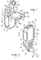
- the protective enclosure according to the present invention is constituted by two half-shells or wings 1 and 1a, which are substantially mirror-symmetrical and are made of insulating plastic material monolithically with a parallelepipedal element 2, which constitutes the terminal block of a connector, and to which they are connected by means of hinges 3-3a ( Figure 1) arranged on two edges of an end face of the parallelepiped 2.
- each cavity constitutes the seat for stably accommodating and retaining one of the chosen terminals 18, which are shown, by way of example, as being of the female Faston type in Figure 2 and in Figure 6.
- Each half-shell 1-1a has two opposite raised edges 5-5a and 6-6a which lie at approximately 90° with respect to the plane of the corresponding half-shell; their width is such that when the half-shells face each other the pairs of edges 5-6 and 5a-6a mate and/or overlap, thus forming a box-like element which contains and protects the leads 17 freed from the cable 16 ( Figures 1 and 6).
- Two internally toothed recesses 8-8a are formed on the edges of the half-cup 7 in order to receive and lock the ends of two toothed straps 9-9a; said two elastically deformable toothed straps 9 and 9a are in fact formed on the edges of the half-cup 7a so as to protrude from the opposite sides of the half-cup, and when the half-shells face each other said straps enter the recesses 8-8a ( Figure 7).
- Figure 6 illustrates the three separate insulating caps 4, 4a and 4b which are adapted to protect the terminals 18 and are joined at the base in a single structure 2 to which the two wings 1 and 1a are connected.
- the protective enclosure thus conceived can be provided with means adapted to ensure engagement to the element 13 to which it is to be connected, by providing on two opposite sides of the terminal block 2 two tabs 10 and 10a which yield elastically and are provided, at their ends, with teeth 11 and 11a which are meant to engage corresponding elements 12 and 12a of the element 13 to be connected, which is provided with the male Faston laminar terminals 14, as shown in Figure 6.
- the outer surfaces of the two wings 1-1a can be made rougher by means of knurled regions 15-15a.
- the cable which is shown as being of the three-pole type by way of example, is designated by the reference numeral 16 as regards its unsheathed part; the insulated leads are designated by the reference numeral 17, and the terminals crimped onto the unsheathed part of the leads are female Faston terminals designated by the reference numeral 18.
- the protective enclosure can also be used to protect other live parts of the motor by placing them inside the chamber formed by its two wings or by shielding them with just one of the wings.
- the operator must first of all take the multicore cable, remove its sheath for a few centimeters, thus freeing the individual insulated leads, and then strip said leads for a few millimeters, exposing the internal metallic wire. He must crimp terminals of the Faston type or the like onto said wire, and then insert the Faston terminals in the cavity 4-4a et cetera of the parallelepipedal element 2 and arrange the leads in the half-shell 1. The operator then folds the two wings 1 and 1a toward each other through 90° or 180° until they mate, thus enclosing in the space between them the insulated leads that protrude from the terminals to which they have been coupled.
- the two facing half-cups can also be clamped together by a toothed tab which is external to the protective enclosure or by virtue of another conventional means without thereby abandoning the scope of the invention.
- the protective enclosure is provided integrally by means of a single molding operation; this is allowed by the fact that it can be molded with the opposite wings 1-1a so set apart at 180° to each other and at 90° to the extraction axes of all the intended holes or seats, without undercuts and without lateral box-like portions, with evident practical and economic advantages.
- Figure 8 illustrates the application of the protective enclosure to an electric motor and the particular improvements to some of its structural elements.
- the electric motor shown in Figure 8 has, in order to receive current, known SIAMEZE terminals which end with laminar contacts of the Faston type 14.
- current is supplied to the motor by mating said laminar contacts 14 with the female Faston contacts 18 that are contained in a protective enclosure according to Figures 1 and 2; two of said contacts are connected to the leads 48 and 46 and carry the current, while the third contact 44 is connected to the ground lead.
- the leads 52 and 53 of the ends of the winding 50 of the spool 36 are placed in the structure 19, which protects them against vibrations and friction against the rotor and other grounded parts of the motor, and are transferred onto the spool 37, where they are mated with the SIAMEZE terminals 49 and 54.
- the terminals of the winding 51 are mated with the SIAMEZE terminals 43 and 49.
- the wires 52 and 53 can be replaced with portions of lead, as shown in the figure, if mass-production of the windings of the two spools requires the anchoring of the ends of the windings to the respective spools for technical reasons.
- the motor according to the present invention connected as shown in Figure 8 and freed from the constraint of the cord or cable (which each customer requires in the length that best suits him), considerably reduces the inventory required to meet customer requirements.
- the invention can provide other embodiments.
- the power supply may have for example six or seven leads if the motor is of the three-phase type.
- the terminals can be of a more modern or less modern type, may have different shapes and dimensions, and may be arranged in more than one row.
- the structures may have different shapes in order to adapt to user devices which are not considered herein.
Landscapes
- Motor Or Generator Frames (AREA)
- Connector Housings Or Holding Contact Members (AREA)
- Coupling Device And Connection With Printed Circuit (AREA)
- Details Of Connecting Devices For Male And Female Coupling (AREA)
Applications Claiming Priority (2)
| Application Number | Priority Date | Filing Date | Title |
|---|---|---|---|
| ITMI000274 | 2000-02-17 | ||
| IT2000MI000274A IT1316760B1 (it) | 2000-02-17 | 2000-02-17 | Struttura di protezione delle connessioni di un cavo elettricomultipopolare ad un connettore e/o ad un motore elettrico e motore |
Publications (2)
| Publication Number | Publication Date |
|---|---|
| EP1128482A2 true EP1128482A2 (fr) | 2001-08-29 |
| EP1128482A3 EP1128482A3 (fr) | 2002-08-21 |
Family
ID=11444057
Family Applications (1)
| Application Number | Title | Priority Date | Filing Date |
|---|---|---|---|
| EP01102849A Withdrawn EP1128482A3 (fr) | 2000-02-17 | 2001-02-13 | Enceinte de protection pour connexions de câble électrique multiconducteur |
Country Status (3)
| Country | Link |
|---|---|
| US (1) | US20010016450A1 (fr) |
| EP (1) | EP1128482A3 (fr) |
| IT (1) | IT1316760B1 (fr) |
Cited By (4)
| Publication number | Priority date | Publication date | Assignee | Title |
|---|---|---|---|---|
| WO2002003505A1 (fr) * | 2000-07-03 | 2002-01-10 | Phoenix Contact Gmbh & Co. | Dispositif de connexion electrique |
| DE102005027538A1 (de) * | 2005-06-15 | 2006-12-28 | Hirschmann Automation And Control Gmbh | Solarstecker mit einem Zugentlastungselement |
| WO2008068164A3 (fr) * | 2006-12-07 | 2008-08-07 | Osram Gmbh | Dispositif de verrouillage pour un connecteur enfichable |
| DE202017105562U1 (de) * | 2017-09-14 | 2018-12-17 | Electro Terminal Gmbh & Co Kg | Klemmenleiterführungsgehäuse |
Families Citing this family (2)
| Publication number | Priority date | Publication date | Assignee | Title |
|---|---|---|---|---|
| JP6018892B2 (ja) * | 2012-11-30 | 2016-11-02 | 矢崎総業株式会社 | 電気接続箱 |
| JP6762329B2 (ja) * | 2018-02-15 | 2020-09-30 | 株式会社オートネットワーク技術研究所 | コネクタ |
Family Cites Families (4)
| Publication number | Priority date | Publication date | Assignee | Title |
|---|---|---|---|---|
| US4280746A (en) * | 1979-05-25 | 1981-07-28 | Western Electric Company, Inc. | Connector arranged to permanently lock onto a cable |
| US4847982A (en) * | 1986-02-06 | 1989-07-18 | Morrill Wayne J | Method of winding a three-phase, one-third pitch motor |
| US4842550A (en) * | 1988-07-01 | 1989-06-27 | Molex Incorporated | Integrally molded environmentally protected strain relief backshell |
| IT223164Z2 (it) * | 1991-03-26 | 1995-06-13 | Fiat Auto Spa | Dispositivo per facilitare e proteggere il collegamento fra cavi con- duttori e relativi terminali di connessione di apparecchiature elettriche, particolarmente dell'elettromagnete di un motore di avviamento per autoveicoli. |
-
2000
- 2000-02-17 IT IT2000MI000274A patent/IT1316760B1/it active
-
2001
- 2001-02-13 EP EP01102849A patent/EP1128482A3/fr not_active Withdrawn
- 2001-02-16 US US09/788,205 patent/US20010016450A1/en not_active Abandoned
Cited By (4)
| Publication number | Priority date | Publication date | Assignee | Title |
|---|---|---|---|---|
| WO2002003505A1 (fr) * | 2000-07-03 | 2002-01-10 | Phoenix Contact Gmbh & Co. | Dispositif de connexion electrique |
| DE102005027538A1 (de) * | 2005-06-15 | 2006-12-28 | Hirschmann Automation And Control Gmbh | Solarstecker mit einem Zugentlastungselement |
| WO2008068164A3 (fr) * | 2006-12-07 | 2008-08-07 | Osram Gmbh | Dispositif de verrouillage pour un connecteur enfichable |
| DE202017105562U1 (de) * | 2017-09-14 | 2018-12-17 | Electro Terminal Gmbh & Co Kg | Klemmenleiterführungsgehäuse |
Also Published As
| Publication number | Publication date |
|---|---|
| ITMI20000274A1 (it) | 2001-08-17 |
| US20010016450A1 (en) | 2001-08-23 |
| IT1316760B1 (it) | 2003-05-12 |
| ITMI20000274A0 (it) | 2000-02-17 |
| EP1128482A3 (fr) | 2002-08-21 |
Similar Documents
| Publication | Publication Date | Title |
|---|---|---|
| US8753141B2 (en) | Adapter for connecting a harness to magnet wires | |
| US5890924A (en) | Insulation-displacement-contact connector | |
| EP1005106B1 (fr) | Borne et procédé de sertissage | |
| EP1003249B1 (fr) | Une borne blindée | |
| US5782652A (en) | Electrical connector assembly for a magnet wire | |
| KR20190039326A (ko) | 포지티브 록 리셉터클용 크러쉬 리브 하우징 | |
| US6126478A (en) | Wiring device with gripping of individual conductors | |
| CN104521075B (zh) | 用于车辆装置的互连组件以及互连方法 | |
| EP1128482A2 (fr) | Enceinte de protection pour connexions de câble électrique multiconducteur | |
| US4176902A (en) | Method for fusing male plug at end of power line cord | |
| ITMI960614U1 (it) | Connettore per motori elettrici in particolare per motori elettrici di macchine lavatrici ed elettrodomestici in genere | |
| KR102455452B1 (ko) | 앵글형 플러그 커넥터 및 조립 방법 | |
| EP0016269B1 (fr) | Fiche électrique | |
| US5653609A (en) | Strain relief for an electrical connector | |
| EP3566239B1 (fr) | Assemblage de porte-bobine protégé thermiquement | |
| EP1115191A2 (fr) | Ensemble de connexion, en particulier pour le bobinage de stator d'un moteur électrique | |
| US4342494A (en) | Electrical connector assembly | |
| US5607321A (en) | Cable plug connector | |
| USRE31017E (en) | Method for fusing male plug at end of power line cord | |
| WO2023244823A2 (fr) | Ensembles enveloppes de connecteur | |
| GB2237455A (en) | Branching electric connector | |
| JP2916630B2 (ja) | 分電ユニット | |
| JP2704486B2 (ja) | 電気コネクタ組立体 | |
| JP2023523034A (ja) | 小型電力コネクタおよびその製造方法 | |
| EP1441433B1 (fr) | Ensemble de connexion, en particulier pour l'enroulement statorique d'un moteur électrique |
Legal Events
| Date | Code | Title | Description |
|---|---|---|---|
| PUAI | Public reference made under article 153(3) epc to a published international application that has entered the european phase |
Free format text: ORIGINAL CODE: 0009012 |
|
| AK | Designated contracting states |
Kind code of ref document: A2 Designated state(s): AT BE CH CY DE DK ES FI FR GB GR IE IT LI LU MC NL PT SE TR |
|
| AX | Request for extension of the european patent |
Free format text: AL;LT;LV;MK;RO;SI |
|
| RAP1 | Party data changed (applicant data changed or rights of an application transferred) |
Owner name: PHOENIX TECHNOLOGIES HOLDING S.A. |
|
| PUAL | Search report despatched |
Free format text: ORIGINAL CODE: 0009013 |
|
| AK | Designated contracting states |
Kind code of ref document: A3 Designated state(s): AT BE CH CY DE DK ES FI FR GB GR IE IT LI LU MC NL PT SE TR |
|
| AX | Request for extension of the european patent |
Free format text: AL;LT;LV;MK;RO;SI |
|
| 17P | Request for examination filed |
Effective date: 20030130 |
|
| AKX | Designation fees paid |
Designated state(s): AT BE CH CY DE DK ES FI FR GB GR IE IT LI LU MC NL PT SE TR |
|
| RAP1 | Party data changed (applicant data changed or rights of an application transferred) |
Owner name: PROMOTIONAL ACTIVITY S.A. |
|
| STAA | Information on the status of an ep patent application or granted ep patent |
Free format text: STATUS: THE APPLICATION HAS BEEN WITHDRAWN |
|
| 18W | Application withdrawn |
Effective date: 20050520 |