EP1128501B1 - Elektrodenanordnung für Gas-Laser - Google Patents
Elektrodenanordnung für Gas-Laser Download PDFInfo
- Publication number
- EP1128501B1 EP1128501B1 EP01104169A EP01104169A EP1128501B1 EP 1128501 B1 EP1128501 B1 EP 1128501B1 EP 01104169 A EP01104169 A EP 01104169A EP 01104169 A EP01104169 A EP 01104169A EP 1128501 B1 EP1128501 B1 EP 1128501B1
- Authority
- EP
- European Patent Office
- Prior art keywords
- electrode
- high voltage
- plate
- laser
- gas
- Prior art date
- Legal status (The legal status is an assumption and is not a legal conclusion. Google has not performed a legal analysis and makes no representation as to the accuracy of the status listed.)
- Expired - Lifetime
Links
- 239000012212 insulator Substances 0.000 claims description 69
- 239000004020 conductor Substances 0.000 claims description 17
- 230000003287 optical effect Effects 0.000 claims description 15
- 229910052751 metal Inorganic materials 0.000 claims description 14
- 239000002184 metal Substances 0.000 claims description 14
- 239000000203 mixture Substances 0.000 claims description 6
- 239000007789 gas Substances 0.000 description 82
- 239000000463 material Substances 0.000 description 16
- 230000005855 radiation Effects 0.000 description 11
- 229910010293 ceramic material Inorganic materials 0.000 description 7
- XKRFYHLGVUSROY-UHFFFAOYSA-N Argon Chemical compound [Ar] XKRFYHLGVUSROY-UHFFFAOYSA-N 0.000 description 6
- 230000013011 mating Effects 0.000 description 6
- KRHYYFGTRYWZRS-UHFFFAOYSA-M Fluoride anion Chemical compound [F-] KRHYYFGTRYWZRS-UHFFFAOYSA-M 0.000 description 5
- 229920006362 Teflon® Polymers 0.000 description 4
- 239000000919 ceramic Substances 0.000 description 4
- 238000005260 corrosion Methods 0.000 description 4
- 230000007797 corrosion Effects 0.000 description 4
- 230000000694 effects Effects 0.000 description 4
- PNEYBMLMFCGWSK-UHFFFAOYSA-N Alumina Chemical compound [O-2].[O-2].[O-2].[Al+3].[Al+3] PNEYBMLMFCGWSK-UHFFFAOYSA-N 0.000 description 3
- 229910052786 argon Inorganic materials 0.000 description 3
- ISQINHMJILFLAQ-UHFFFAOYSA-N argon hydrofluoride Chemical compound F.[Ar] ISQINHMJILFLAQ-UHFFFAOYSA-N 0.000 description 3
- 238000011109 contamination Methods 0.000 description 3
- TWNQGVIAIRXVLR-UHFFFAOYSA-N oxo(oxoalumanyloxy)alumane Chemical compound O=[Al]O[Al]=O TWNQGVIAIRXVLR-UHFFFAOYSA-N 0.000 description 3
- 239000004033 plastic Substances 0.000 description 3
- 238000007789 sealing Methods 0.000 description 3
- 229910052782 aluminium Inorganic materials 0.000 description 2
- XAGFODPZIPBFFR-UHFFFAOYSA-N aluminium Chemical compound [Al] XAGFODPZIPBFFR-UHFFFAOYSA-N 0.000 description 2
- 150000004820 halides Chemical class 0.000 description 2
- 239000001307 helium Substances 0.000 description 2
- 229910052734 helium Inorganic materials 0.000 description 2
- SWQJXJOGLNCZEY-UHFFFAOYSA-N helium atom Chemical compound [He] SWQJXJOGLNCZEY-UHFFFAOYSA-N 0.000 description 2
- 238000009413 insulation Methods 0.000 description 2
- OKTJSMMVPCPJKN-UHFFFAOYSA-N Carbon Chemical compound [C] OKTJSMMVPCPJKN-UHFFFAOYSA-N 0.000 description 1
- 229910052799 carbon Inorganic materials 0.000 description 1
- 238000010276 construction Methods 0.000 description 1
- 238000010494 dissociation reaction Methods 0.000 description 1
- 230000005593 dissociations Effects 0.000 description 1
- 239000000428 dust Substances 0.000 description 1
- 230000005281 excited state Effects 0.000 description 1
- 150000002222 fluorine compounds Chemical class 0.000 description 1
- 231100001261 hazardous Toxicity 0.000 description 1
- 239000011810 insulating material Substances 0.000 description 1
- 238000012423 maintenance Methods 0.000 description 1
- 229910052754 neon Inorganic materials 0.000 description 1
- GKAOGPIIYCISHV-UHFFFAOYSA-N neon atom Chemical compound [Ne] GKAOGPIIYCISHV-UHFFFAOYSA-N 0.000 description 1
- 230000003595 spectral effect Effects 0.000 description 1
- 231100000331 toxic Toxicity 0.000 description 1
- 230000002588 toxic effect Effects 0.000 description 1
Images



Classifications
-
- H—ELECTRICITY
- H01—ELECTRIC ELEMENTS
- H01S—DEVICES USING THE PROCESS OF LIGHT AMPLIFICATION BY STIMULATED EMISSION OF RADIATION [LASER] TO AMPLIFY OR GENERATE LIGHT; DEVICES USING STIMULATED EMISSION OF ELECTROMAGNETIC RADIATION IN WAVE RANGES OTHER THAN OPTICAL
- H01S3/00—Lasers, i.e. devices using stimulated emission of electromagnetic radiation in the infrared, visible or ultraviolet wave range
- H01S3/02—Constructional details
- H01S3/03—Constructional details of gas laser discharge tubes
- H01S3/038—Electrodes, e.g. special shape, configuration or composition
-
- H—ELECTRICITY
- H01—ELECTRIC ELEMENTS
- H01S—DEVICES USING THE PROCESS OF LIGHT AMPLIFICATION BY STIMULATED EMISSION OF RADIATION [LASER] TO AMPLIFY OR GENERATE LIGHT; DEVICES USING STIMULATED EMISSION OF ELECTROMAGNETIC RADIATION IN WAVE RANGES OTHER THAN OPTICAL
- H01S3/00—Lasers, i.e. devices using stimulated emission of electromagnetic radiation in the infrared, visible or ultraviolet wave range
- H01S3/14—Lasers, i.e. devices using stimulated emission of electromagnetic radiation in the infrared, visible or ultraviolet wave range characterised by the material used as the active medium
- H01S3/22—Gases
- H01S3/223—Gases the active gas being polyatomic, i.e. containing two or more atoms
- H01S3/225—Gases the active gas being polyatomic, i.e. containing two or more atoms comprising an excimer or exciplex
Definitions
- the present invention relates to gas discharge lasers, and in particular to excimer lasers, and more particularly to an electrode arrangement for such gas discharge lasers.
- Excimer lasers provide high intensity laser radiation in the ultraviolet spectral range. This makes them important tools especially for medical and surgical applications as well as for other industrial applications.
- Excimer lasers are gas discharge lasers, which use a rare gas such as argon and a halide gas such as fluor (for example ArF excimer laser) or a gas containing a halide (for example F 2 ) as the laser gas.
- a rare gas such as argon
- a halide gas such as fluor (for example ArF excimer laser) or a gas containing a halide (for example F 2 ) as the laser gas.
- excimer laser a gas mixture containing the active component and other gases is steadily provided to a discharge gap between a pair of elongated electrodes inside the laser tube by means of a fan or the like.
- a high voltage applied between the two electrodes causes a gas discharge in said discharge gap, whereby, from the active component of the gas, short-lived excited-state molecules are generated, whose dissociation generates ultraviolet radiation constituting the laser radiation.
- a pre-ionization of the laser gas by pre-ionizers is used.
- excimer lasers are generally operated in a pulsed operation mode, wherein the laser gas in the discharge gap is being steadily replaced by fresh or regenerated laser gas provided by the fan.
- the discharge electrodes of an excimer laser are usually located inside the laser tube.
- the housing of an excimer laser generally consists of a metal tube having openings in a cylindrical wall on the upper side thereof. The open upper side is covered by an insulating plate. The metal tube and one of the discharge electrodes are grounded. A high voltage is applied to the second discharge electrode via a HV duct extending through the insulating plate.
- That main insulator is made of a ceramic material such as aluminium oxide.
- Another, even more corrosion-resistive, material, which can be used, as insulators are fluorides.
- Such a mechanism would not only extend the lifetime of the insulators, but also perhaps more importantly significantly lower the dust in the gas mixture within the laser tube.
- the present invention may be used in conjunction with the inventions described in the patent applications US 09/510,538, US 09/510,539, US 09/510,666, US 09/510,667, US 09/511,648, and US 511,649.
- One object of the present invention is to provide an electrode arrangement for a gas laser, and in particular for an excimer laser, that minimizes contamination of the laser gas and thus increases the lifetime of the laser gas.
- Another object of the present invention is to provide an electrode arrangement for a gas laser and in particular for an excimer laser that is easy to handle and yet powerful.
- an electrode arrangement as defined in claim 1 for a gas laser comprising an elongated high voltage electrode, an elongated ground electrode disposed adjacent to the high voltage electrode, a gas discharge gap between the two electrodes in which the gas discharge for the laser is generated, an insulator element, a high voltage conductor extending through the insulator element and having a first end connected to the high voltage electrode, and a shadow plate interposed between the gas discharge gap and the insulator element for shielding the insulator element against laser radiation irradiated from the gas discharge gap, as well as from gas discharge radiation and pre-ionization radiation.
- the shadow plate is preferably made of a high purity metal, such as aluminum.
- it can be made of an insulator material, such as a heat resistant plastic material, such as TEFLON®, or a ceramic material, which is then covered by a metal, preferably of high purity.
- the shadow plate can be made of any other material, which is resistant against the laser gas and the laser radiation, gas discharge radiation, and pre-ionizer radiation.
- the shadow plate can be arranged at any location between the gas discharge gap and the insulator element. For example, it can be located directly above the discharge gap on the high voltage electrode, or it can be located on the high voltage conductor. Preferably, the shadow plate is interposed between the high voltage electrode and the high voltage conductor.
- the insulator may comprise an elongated shape and extend continuously substantially over the entire length of the laser tube and thus form a prior art electrode plate, which serves as an upper cover for the laser tube, and through which the high voltage electrode extends.
- Each high voltage duct comprises a central conductive core having a first end and an insulator element, preferably made of a ceramic material.
- the insulator element is disposed around the core, preferably in a concentrical manner, to electrically insulate the core and electrode plate from each other.
- the electrode arrangement according to the preferred embodiment further comprises an elongated high voltage electrode electrically connected to the first end of the cores of the ducts, an elongated ground electrode positioned to oppose the high voltage electrode and form a gas discharge gap therebetween, the ground electrode being electrically connected to the electrode plate, and a shadow plate interposed between the gas discharge gap and the insulator element of each of the ducts.
- the electrode plate As the electrode plate is grounded, an insulator is required between the conductive cores of the HV ducts and the electrode plate.
- the number of high voltage ducts (and holes) depends on the size of the laser, in particular on the length of the electrodes. For example, for a typical excimer laser, three high voltage ducts should be used. For a larger laser with longer electrodes more than three ducts should be provided. For smaller lasers with shorter electrodes only one or two ducts may be provided.
- the coaxial ducts comprise a round cross-section so that commercially available parts can be used.
- the ducts can comprise any cross-sectional shape, such as square or rectangular or oblong or anything else.
- the shadow plates can be flat. Preferably, however, the edges of the shadow plate are bent towards the insulator elements. The edges of the shadow plate are preferably bent towards the insulator element for ensuring a more efficient shading of the insulator. Furthermore, the shadow plate desirably comprises a flow guiding shape to help guide the laser gas mixture, which typically comprises the laser gas and a buffer gas into the gas discharge gap.
- the preferred discharge unit further comprises a pair of standard corona pre-ionizers, that is a pair of elongated cylindrical pre-ionizers with a conductive core and a surrounding tube-shaped insulator.
- the pre-ionizers extend substantially parallel along opposite sides of the electrode.
- the insulator of the pre-ionizers can be TEFLON®, or any suitable insulator, but it is preferably a ceramic material, such as aluminum oxide.
- the insulator can also be a fluoride material. Alternatively, any other kind of known pre-ionizer can be used.
- the pre-ionizers are not necessary for the discharge unit to work. Indeed, excimer lasers were known before the invention of pre-ionizers. Pre-ionization, however makes the gas discharge between the high voltage electrode and the ground electrode more homogeneous and thus more reliable.
- the overall construction of the laser can be such that first a laser tube is provided, and then the high voltage electrode, the ground electrode, the insulator element or elements, the high voltage conductor or conductors, the pre-ionizers and the shadow plate are mounted to the tube, one by one. It is preferred, however, that the electrode arrangement is a pre-mounted module-type discharge unit, wherein the electrodes, the shadow plate, the pre-ionizers and the high voltage ducts are pre-mounted independently of other laser elements. In this manner, the discharge unit can be mounted to the laser tube as a whole. This provides several advantages. One advantage is that the gas discharge gap between the high voltage electrode and the ground electrode can be adjusted before the discharge unit is mounted into the laser tube. This facilitates an accurate adjustment of the gas discharge gap. Furthermore the mounting of the laser can be done in a more efficient manner.
- the laser gas can, in the case of an excimer laser, be any excimer laser gas, such as KrF, ArF, XeF, XeBr, HgBr, HgCI, XeCl, HCI, F 2 , Ar 2 and the like or any laser gas in case of some other gas discharge laser.
- excimer laser gas such as KrF, ArF, XeF, XeBr, HgBr, HgCI, XeCl, HCI, F 2 , Ar 2 and the like or any laser gas in case of some other gas discharge laser.
- a buffer gas comprising a mixture of Helium, Neon and/or Argon is preferably provided in the tube.
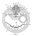
- Figures 1 and 2 show an excimer laser 100 comprising a tube 101, a discharge unit 102, a circulation means 201, and a laser optical system 103.
- the circulation means 201 is optional and may comprise, for example, a fan or any other means known for circulating lasing gases in gas lasers.
- the discharge unit 102 is mounted into the tube 101 and comprises a high voltage electrode 104 and the ground electrode 105.
- the high voltage electrode 104 and the ground electrode 105 are spaced apart from each other, thereby defining a gas discharge gap 106.
- a high voltage is applied to the high voltage electrode 104 via a plurality of high voltage ducts 107, which carry the high voltage electrode 104.
- Each high voltage duct 107 comprises a conductive core 108 and an insulator element 110 arranged around the conductive core 108.
- Each high voltage duct 107 is attached to the high voltage electrode 104.
- the high voltage ducts may be attached to the high voltage electrode using any suitable fastener.
- a double threaded stud 112 is used to attach electrode 104 to each conductive core 108 of each duct 107.
- discharge unit 102 is provided with an elongated electrode plate 111.
- the electrode plate 111 includes holes, through which the high voltage ducts 107 extend so as to be connected to the high voltage electrode 104.
- Each high voltage duct 107 is fixed to the electrode plate 111 by an attachment means, such as bolts 113.
- any suitable attachment means may be used to fix ducts 107 to electrode plate 111.
- the insulator elements 110 are preferably made of a ceramic material.
- they may be made from other isolative materials, including, for example, a fluoride material. They have a shape, which conically expands towards the high voltage electrode 104, and comprise a corrugated surface, so as to increase a creepage path extending along said surface. This helps to prevent surface flashover between the high voltage electrode 104 and the grounded electrode plate 111.
- insulator elements 110 may be made from fluoride insulator material. These materials have the drawback of being relatively expensive. However, according to the preferred embodiment of the present invention, only a small amount of insulator material is required. Accordingly, the use of fluoride insulator materials is affordable in the present invention.
- discharge unit 102 also preferably comprises a shadow plate 210 disposed between the gas discharge gap 106 and the insulator element 110 for protecting the insulator element 110 against the corrosive effects of the laser gas and of the laser, gas discharge, and pre-ionizer radiation.
- Shadow plate 210 is preferably made out metal, such as aluminum. A high purity metal is particularly preferred for use in constructing shadow plate 210.
- shadow plate 210 is interposed between the high voltage electrode 104 and insulator element 110 of the ducts 107.
- shadow plate 210 extends along the entire gas discharge gap 106 and is mounted in such a manner that it at least partially shields the insulator element against the laser radiation irradiated from the gas discharge gap 106.
- shadow plate 210 preferably has an elongated sheet-like shape and comprises a central portion 209, a first edge portion 211 and a second edge portion 212.
- the central portion 209 extends longitudinally in a direction parallel to the gas discharge gap 106 and perpendicular to the cores 108 of the high voltage ducts 107.
- the edge portions 211 and 212 are located at the longitudinal edges of the shadow plate 210 and are, with respect to the central portion 209, preferably bent towards the insulator elements 110 by a small angle of about 20 degrees.
- shadow plate 210 is preferably elongated as described above, it may have a variety of other shapes as well.
- a plurality of shadow plates 210 could be used instead of one elongated shadow plate that extends the length of the discharge gap.
- the shadow plates would preferably be circular and have a cross-sectional appearance consistent with that shown in Figure 2.
- a circular shadow plate 210 could be interposed between the electrode 104 and each insulator element 110 of the high voltage ducts 107.
- the shadow plate 209 may be interposed between the high voltage electrode 104 and inner ends 404 of the cores 108 of the high voltage ducts 107 so that the longitudinal axis of the central portion 209 (or center in the case of a circular shadow plate) coincides with the central axis of the high voltage electrode 104.
- shadow plate 210 is preferably interposed between high voltage electrode 104 and inner ends 404 of the cores 108 as illustrated in Figure 2, as those skilled in the art will appreciate, the shadow plate 210 will serve its desired function so long as it is interposed between the discharge gap 106 and insulator elements 110. Thus, the positioning of shadow plate 210 is not limited to the position illustrated in Figure 2.
- Shadow plate 210 may be interposed between electrode 104 and cores 108 by providing central portion 209 with a plurality of holes 213, preferably along the longitudinal axis of the central portion 209, and then attaching high voltage electrode 104 to the cores 108 through holes 213 using a suitable fastener.
- the spacing and the number of holes 213 correspond to the spacing and the number of high voltage ducts 107.
- stud bolts 112 with threads on both ends are used to attach electrode 104 to cores 108.
- One end of the stud bolt 112 is inserted into a threaded hole 124 provided in the respective core 108.
- each shadow plate will be provide with a single hole 213 in the center of the shadow plate and one shadow plate will be used for each high voltage duct employed in the laser.
- the shadow plate 210 preferably has a flow guiding shape to help guide the lasing gas mixture into the gas discharge gap 106.
- a stud bolt 112 is screwed into each of the threaded holes provided on the mating face 128 of the high voltage electrode 104, such that the other end of each stud bolt 112 stands out of the mating face 128. Then the shadow plate 210 is arranged on the mating face 128 of the high voltage electrode 104 so that the stud bolts 112 are inserted into the holes 213 in the shadow plate 210. Alternatively, if a circular shadow plate is used, then one shadow plate 210 will be inserted over each of the stud bolts 112.
- a core 108 of the high voltage ducts 107 is lowered upon the shadow plate 210, such that the end of one of the stud bolt protruding from electrode partially enters the threaded hole 124 provided in the inner end 404 of the core 108 of the high voltage duct 107.
- the core 108 is rotated around its longitudinal axis, i.e. around the longitudinal axis of the stud bolt 112, so as to screw the core 108 onto the stud bolt 112.
- the core 108 is lowered onto the shadow plate 210, and the shadow plate 210 is finally held between the upper face 128 of the high voltage electrode 104 and the inner end 404 of the core 108.
- Additional high voltage ducts 107 comprising cores 108 are attached to the remaining stud bolts 112 in the same way as described above.
- the excimer laser 100 is preferably a pulsed argon fluoride (ArF) excimer laser with a wavelength of about 193 nanometers.
- ArF argon fluoride
- argon fluoride gas is used for generating a laser beam.
- any of the known excimer laser gases may be used in connection with the present invention.
- the laser gas e.g., argon fluoride gas
- helium and/or argon gas as a buffer gas in the discharge gap 106 generate a laser beam which is emitted through the laser optical system comprising a front optical system 103 and a rear optical system 120.
- Laser 100 typically further comprises a front optical element 116, through which the laser beam emits.
- Optical element 116 may be provided, for example, in an optical system 103, which includes an adjustable mounting means 117 for adjusting the position of the optical element 116 in relation to the tube 101.
- Rear laser optical system 120 similarly includes an optical element 116 (not shown) and adjusting means 117.
- the optical element 116 of the rear laser optical system 120 comprises a totally reflective mirror rather than a partially reflective mirror.
- front and rear optical elements 116 may also be mounted directly in the end walls of the laser tube 101. Alternatively, they may be mounted on adjustable mounting brackets, which are separate from the laser tube 101 as is known in the art.
- FIG. 2 is a cross-sectional view along line 2-2 of the excimer laser 100 shown in Fig. 1.
- the excimer laser 100 preferably further includes a circulating means 112, such as a fan, for circulating the excimer laser gas through the discharge gap 106 and an optional dedusting unit 202 for dedusting the gas flow through the tube 101.
- the dedusting unit comprises high voltage wires 203, separated from each other by U-shaped channels 204 extending along the tube 101.
- two guiding plates 205 which are elongated in the longitudinal direction of the tube 101 are preferably provided for guiding the gas flow through discharge gap 106 and a portion of such gas into dedusting unit 202. After exiting dedusting unit 202, the gas returns to fan 201 to be re-circulated through the laser 101.
- the ground electrode 105 is preferably carried by, or mounted to, the electrode plate 111 via a plurality of flow guides 209, which will be referred to again later.
- pre-ionizers 206 Adjacent to the high voltage electrode 104, two pre-ionizers 206 are provided, which serve to pre-ionize the laser gas to ensure greater homogeneity of the gas discharge in the discharge gap 106.
- the pre-ionizers 206 are preferably corona-type pre-ionizers and extend substantially parallel to said high voltage electrode.
- the pre-ionizers 206 have a coaxial shape with a conductive core 207 surrounded by a tube shaped insulator 208.
- the corona-type pre-ionizers can be mounted immediately adjacent to the high voltage electrode.
- the corona-type pre-ionizers should be mounted at the opposing edges of the high voltage electrode so that it is disposed adjacent the electrode face of the high voltage electrode facing the ground electrode.
- corona-type pre-ionizers are preferred for use as pre-ionizers 206 in connection with the present invention, those skilled in the art will recognize that any of the pre-ionizers known in the art may be used.
- the insulator of the pre-ionizers can be TEFLON®, or any suitable insulator, but it is preferably a ceramic material. It can also be a fluoride material. Alternatively, any other kind of known pre-ionizer can be used.
- the pre-ionizers are not necessary for the discharge unit to work. Indeed, excimer lasers were known before the invention of pre-ionizers. Pre-ionization, however makes the gas discharge between the high voltage electrode and the ground electrode more homogeneous and thus more reliable.
- the discharge unit 102 comprises three coaxial waveguide-like high voltage ducts 107, extending through holes in the electrode plate 111.
- the ducts 107 are arranged spaced apart from each other.
- the holes and the ducts 107 have a circular cross section, as can be seen from Figure 3c.
- Each of the three ducts 107 is inserted into the respective hole in the electrode plate 111 with a defined tolerance between the insulator element and the hole.
- the number of ducts employed in a particular gas laser 100 will depend on the overall length of the laser.
- the ground electrode 105 is preferably carried by, or mounted to, the electrode plate 111. As best seen in Figs. 2 and 3a, preferably a plurality of flow guides 209 are used for this purpose.
- the flow guides 209 are preferably made from sheets of metal that extend between the electrode plate and the ground electrode in a plane perpendicular to the longitudinal axis of the electrodes 104, 105.
- the flow guides plates 209 comprise respectively an upper flange 301, a lower flange 303, and a central flow guiding portion 302 integrally connecting said upper flange 301 to said lower flange 303.
- Said upper and lower flanges 301, 303 extend perpendicular to each other and to said central flow guiding portion 302.
- the upper flange 301 is attached to a side face 304 of electrode plate 111, and the lower flange 303 is attached to a bottom face 305 of the ground electrode 105.
- the central flow guiding portion 302 is preferably aerodynamically profiled in order to minimize flow resistance and turbulences for maintaining a substantially laminar gas flow between the flow guides.
- the lower flange 303 preferably includes an oblong hole 306 (shown only at part of the flow guiding plates 209). Hole 306 is oblong in a direction perpendicular to the longitudinal axis of the elongated ground electrode 105. A screw, or other fastening means, 307 is inserted through the hole 306 into a mating threaded hole 308 being provided in the ground electrode 105.
- the oblong hole 306 allows for adjustments of the ground electrode 105 with respect to the high voltage electrode 104 essentially in the direction indicated by the double-headed arrow 320 in Figure 3c.
- the upper flange 301 preferably includes an oblong hole 309. Hole 309 being oblong in a direction perpendicular to the longitudinal axis of the electrode plate 111. A screw, or other fastening means, 310 is inserted through the hole 309 into a mating threaded hole 311 being provided in the high voltage electrode 104.
- the oblong hole 309 allows an adjustment of the ground electrode 105 with respect to the high voltage electrode 104 essentially in the direction indicated by the double-headed arrow 322 in Figure 3a.
- FIG. 4 shows a cross section of the discharge unit 102 according to the preferred embodiment of the invention.
- Fig. 4 shows an enlarged cross-sectional view of the discharge unit shown in Fig. 2.
- the angle of view is the same as in Figure 3b.
- Each high voltage duct 107 of the laser discharge unit 102 preferably further comprises a sleeve 401 enclosing the core 108 and insulator 110.
- Sleeve 401 has an inner end 402 supported by the electrode plate 111, and an outer free end 403.
- the core 108 has an inner end 404 connected to the high voltage electrode 104 and a threaded outer free end 405 extending beyond the free end 403 of the sleeve 401.
- a nut 406 may be screwed onto the threaded end 405 as shown in Figs. 3c and 4, thereby pressing the sleeve 401 against the electrode plate 111 and tensioning the core 108 by pulling it.
- a washer 450 is interposed between nut 406 and insulator 110 to evenly distribute the stresses applied by nut 406 to insulator 110.
- a threaded stud bolt 112 is used to connect the inner end 404 of the core 108 to the high voltage electrode 104.
- the inner end 404 of the core 108 is provided with a core ring shoulder 408, which is pressed against the ceramic insulator element 110 when core 108 is placed under tension.
- a seal 409 is preferably provided between the ring shoulder 408 and the ceramic insulator element 110.
- the ceramic insulator element 110 is also caused to be pressed against the electrode plate 111 by means of the tensioned core 108 via the core ring shoulder 408 at the inner end 404 of the core 108.
- a ring shoulder 410 is provided on the insulator element 110 and another seal 411 is provided between the ceramics insulator ring shoulder 410 and the electrode plate 111.
- a sealing ring 412 (see also Figures 2 and 3c) preferably surrounds each sleeve 401.
- Sealing ring 412 may be constructed to have a flange 413 at its outer circumference. Flange 413 is dimensioned so that it is supported by an outer rim 414 of the holes 150 in the tube 101 through which the respective ducts 107 are inserted.
- Electrode plate 111 is then preferably provided with a ring shoulder 417 facing an inner rim 415 of the tube 101.
- a metal seal 416 is preferably interposed between shoulder 417 and rim 415.
- seals 409, 411 and 416 are ring-shaped metal seals in the present embodiment. However, those skilled in the art will appreciate that the invention is not limited to using ring-shaped seals.
Landscapes
- Physics & Mathematics (AREA)
- Electromagnetism (AREA)
- Engineering & Computer Science (AREA)
- Plasma & Fusion (AREA)
- Optics & Photonics (AREA)
- Lasers (AREA)
Claims (19)
- Elektrodenanordnung für einen Gaslaser mit:einer langgestreckten Hochspannungselektrode (104);einer langgestreckten Erdelektrode (105), die benachbart zur Hochspannungselektrode (104) angeordnet ist;einem Entladungsspalt (106) zwischen den zwei Elektroden;einem Isolatorelement (110), das seitlich in die Entladungszone hervorragt;einem Hochspannungsleiter (107), der sich durch das Isolatorelement (110) erstreckt und ein erstes Ende aufweist, das mit der Hochspannungselektrode (104) verbunden ist; undeiner Schattenplatte (210), die zwischen den Entladungsspalt (106) und das Isolatorelement (110) eingefügt ist.
- Elektrodenanordnung nach Anspruch 1, wobei die Schattenplatte (210) zwischen die Hochspannungselektrode (104) und das erste Ende des Hochspannungsleiters (107) eingefügt ist.
- Elektrodenanordnung nach Anspruch 1, wobei das Isolatorelement (110) eine langgestreckte Form aufweist und sich entlang im Wesentlichen der gesamten Länge der Elektroden (104, 105) erstreckt.
- Elektrodenanordnung nach Anspruch 1, wobei die Schattenplatte (210) eine Kante umfaßt, die in Richtung des Isolatorelements (110) gebogen ist.
- Elektrodenanordnung nach Anspruch 1, wobei die Schattenplatte (210) eine Strömungsführungsform aufweist, um über ihre Oberfläche strömendes Gas in den Entladungsspalt zu führen.
- Elektrodenanordnung nach Anspruch 1, wobei die Elektroden (104, 105), die Schattenplatte (210), das Isolatorelement (110) und der Hochspannungsleiter zusammengefügt sind, um ein entfernbar montierbares Modul zu bilden.
- Elektrodenanordnung nach Anspruch 6, wobei die Schattenplatte (210) zwischen die Hochspannungselektrode (104) und den Hochspannungskanal (107) eingefügt ist.
- Elektrodenanordnung nach Anspruch 6, wobei das Isolatorelement (110) eine langgestreckte Form aufweist und sich entlang im Wesentlichen der gesamten Länge der Elektroden (104, 105) erstreckt.
- Elektrodenanordnung nach Anspruch 6, wobei die Schattenplatte (210) eine in Richtung des Isolatorelements gebogene Kante umfaßt.
- Elektrodenanordnung nach Anspruch 6, wobei die Schattenplatte (210) eine Strömungsführungsform umfaßt, die geformt ist, um über ihre Oberfläche strömendes Gas in den Entladungsspalt (106) zu führen.
- Elektrodenanordnung nach Anspruch 1, welche zur Verwendung in einem Excimerlaser ausgelegt ist.
- Elektrodenanordnung nach Anspruch 1, wobei die Schattenplatte (210) mindestens eine Metallfläche, insbesondere aus Metall mit hoher Reinheit, aufweist.
- Elektrodenanordnung nach Anspruch 12, wobei die Schattenplatte (210) aus einem Metall mit hoher Reinheit besteht.
- Entladungseinheit mit mindestens einer Elektrodenanordnung nach Anspruch 1, in welcher sich befindet:eine langgestreckte Elektrodenplatte (111), die aus einem elektrisch leitenden Material besteht und eine Vielzahl von beabstandeten Löchern darin aufweist;eine Vielzahl von koaxialen Hochspannungskanälen (107), wobei sich jeder Kanal (107) durch eines der Löcher in der Elektrodenplatte (111) erstreckt und jeder Kanal (107) einen zentralen leitenden Kern (108) mit einem ersten Ende und ein Isolatorelement (110), das um den Kern (108) angeordnet ist und den Kern von der Elektrodenplatte elektrisch isoliert, umfaßt;eine langgestreckte Hochspannungselektrode (104), die mit dem ersten Ende der Kerne der Kanäle elektrisch verbunden ist;eine langgestreckte Erdelektrode (105), die so angeordnet ist, daß sie der Hochspannungselektrode gegenüberliegt und einen Gasentladungsspalt (106) dazwischen bildet, wobei die Erdelektrode (105) mit der Elektrodenplatte (111) elektrisch verbunden ist; undeine Schattenplatte (210), die zwischen den Gasentladungsspalt (106) und das Isolatorelement (110) von jedem der Kanäle (107) eingefügt ist.
- Entladungseinheit nach Anspruch 14, wobei die Schattenplatte (210) zwischen die Hochspannungselektrode (104) und das erste Ende des Kerns von jedem der Kanäle eingefügt ist.
- Verwendung einer Elektrodenanordnung nach Anspruch 1 in einem Gaslaser, in dem sich eine abgedichtete Röhre, die Metall umfaßt, befindet, wobei die Röhre ein Gasgemisch enthält, das ein Lasergas umfaßt;die langgestreckte Hochspannungselektrode (104) innerhalb der Röhre angeordnet ist und sich parallel zur Längsachse der Röhre erstreckt;die langgestreckte Erdelektrode (105) innerhalb der Röhre benachbart zur Hochspannungselektrode (104) angeordnet ist, wobei sich die Erdelektrode (105) parallel zur Hochspannungselektrode (104) erstreckt und von der Hochspannungselektrode beabstandet ist, wodurchder langgestreckte Entladungsspalt (106) zwischen den zwei Elektroden gebildet wird;der Hochspannungsleiter (107) sich durch eine Wand der Röhre erstreckt, das zweite Ende des Hochspannungsleiters außerhalb der Röhre angeordnet ist;das Isolatorelement (110) um den Hochspannungsleiter (107) angeordnet ist und den Leiter von den Metallteilen der Röhre isoliert;ein Zirkulationsmittel (201) innerhalb der Röhre angeordnet ist;ein erstes laseroptisches Element an einem Ende des Entladungsspalts angeordnet ist; undein zweites laseroptisches Element am entgegengesetzten Ende des Entladungsspalts angeordnet ist.
- Verwendung einer Elektrodenanordnung in einem Gaslaser nach Anspruch 16, wobei die Elektroden (104, 105), die Schattenplatte (210), das Isolatorelement (110) und der Hochspannungsleiter (107) zusammengefügt werden, um eine entfernbar montierbare Entladungseinheit zu bilden, und wobei die Elektroden relativ zueinander einstellbar sind, wenn die Entladungseinheit (102) aus der Röhre entfernt wird.
- Verwendung einer Elektrodenanordnung in einem Gaslaser nach Anspruch 16, wobei die Schattenplatte (210) zwischen die Hochspannungselektrode (104) und das erste Ende des Hochspannungsleiters (107) eingefügt wird.
- Verwendung einer Elektrodenanordnung in einem Gaslaser nach Anspruch 16, welche ferner umfaßt:eine Entladungseinheit (102), die entfernbar innerhalb der Röhre montiert ist, wobei die Entladungseinheit eine langgestreckte Elektrodenplatte (111), die aus einem leitenden Material besteht und eine Vielzahl von beabstandeten Löchern (213) darin aufweist, eine Vielzahl von koaxialen Hochspannungskanälen (107), wobei sich jeder Kanal (107) durch eines der Löcher (213) in der Elektrodenplatte (111) erstreckt und einen zentralen leitenden Kern (108) und ein Isolatorelement (110) umfaßt, das um den Kern angeordnet ist und den Kern (108) von der Elektrodenplatte (111) elektrisch isoliert, eine langgestreckte Hochspannungselektrode (104), die mit den Kernen der Kanäle (107) verbunden ist, eine langgestreckte Erdelektrode (105), die einstellbar an der Elektrodenplatte (111) montiert ist, so daß sie von der Hochspannungselektrode (104) beabstandet und zu dieser im wesentlichen parallel ist, und eine Schattenplatte (210), die zwischen den Entladungsspalt (106) und das Isolatorelement (110) von jedem der Kanäle (107) eingefügt ist, umfaßt.
Applications Claiming Priority (2)
| Application Number | Priority Date | Filing Date | Title |
|---|---|---|---|
| US09/510,017 US6480517B1 (en) | 2000-02-22 | 2000-02-22 | Shadow device for a gas laser |
| US510017 | 2000-02-22 |
Publications (3)
| Publication Number | Publication Date |
|---|---|
| EP1128501A2 EP1128501A2 (de) | 2001-08-29 |
| EP1128501A3 EP1128501A3 (de) | 2002-08-07 |
| EP1128501B1 true EP1128501B1 (de) | 2004-12-15 |
Family
ID=24029028
Family Applications (1)
| Application Number | Title | Priority Date | Filing Date |
|---|---|---|---|
| EP01104169A Expired - Lifetime EP1128501B1 (de) | 2000-02-22 | 2001-02-21 | Elektrodenanordnung für Gas-Laser |
Country Status (3)
| Country | Link |
|---|---|
| US (1) | US6480517B1 (de) |
| EP (1) | EP1128501B1 (de) |
| DE (1) | DE60107733T2 (de) |
Families Citing this family (1)
| Publication number | Priority date | Publication date | Assignee | Title |
|---|---|---|---|---|
| JP7572545B2 (ja) | 2020-09-29 | 2024-10-23 | サイマー リミテッド ライアビリティ カンパニー | レーザチャンバの封止機構のための電磁シールド |
Family Cites Families (42)
| Publication number | Priority date | Publication date | Assignee | Title |
|---|---|---|---|---|
| US3400596A (en) | 1966-04-15 | 1968-09-10 | Spectra Physics | Adjustable optical element supporting apparatus |
| US4746201A (en) | 1967-03-06 | 1988-05-24 | Gordon Gould | Polarizing apparatus employing an optical element inclined at brewster's angle |
| US3753144A (en) | 1971-10-18 | 1973-08-14 | W Kearns | Gas laser structure |
| DE2255048A1 (de) | 1972-11-10 | 1974-05-09 | Isco Optische Werke Gmbh | Kunststoff-fassung fuer objektive mit veraenderbarer brennweite |
| US3886474A (en) | 1973-04-30 | 1975-05-27 | Coherent Radiation | Gas laser having an integral optical resonator with external stabilizing means |
| US4423510A (en) * | 1979-08-17 | 1983-12-27 | Westinghouse Electric Corp. | Laser tube design incorporating low inductance capacitor |
| US4448385A (en) | 1981-05-12 | 1984-05-15 | Honeywell Inc. | Stable alignment mechanism for laser mirrors |
| DE3130399A1 (de) | 1981-07-31 | 1983-02-17 | Siemens AG, 1000 Berlin und 8000 München | Optischer sender (laser) mit einer justiervorrichtung fuer einen reflektorspiegel des laserresonators |
| JPS5861843A (ja) | 1981-09-12 | 1983-04-13 | Senichi Masuda | 極短パルス高電圧発生装置 |
| DE3212928C2 (de) | 1982-04-07 | 1984-01-26 | Lambda Physik GmbH, 3400 Göttingen | Entladungsgepumpter Laser |
| EP0166028A3 (de) | 1984-06-25 | 1987-04-22 | Siemens Aktiengesellschaft | Justiereinrichtung für einen Reflektorspiegel eines Laserresonators |
| US4686685A (en) | 1985-06-06 | 1987-08-11 | Laser Corporation Of America | Gas laser having thermally stable optical mount |
| DE3541744A1 (de) | 1985-11-26 | 1987-05-27 | Heraeus Gmbh W C | Gaslaser |
| JP2512137Y2 (ja) | 1986-03-28 | 1996-09-25 | 日本電気株式会社 | ガスレ−ザ発振器 |
| DE3718467A1 (de) | 1987-06-02 | 1988-12-15 | Siemens Ag | Justiereinrichtung fuer ein optisches element |
| US4891818A (en) | 1987-08-31 | 1990-01-02 | Acculase, Inc. | Rare gas-halogen excimer laser |
| US5473162A (en) | 1987-10-26 | 1995-12-05 | Baylor University | Infrared emission detection of a gas |
| US5048041A (en) * | 1988-01-15 | 1991-09-10 | Cymer Laser Technologies | Compact excimer laser |
| JPH02250383A (ja) | 1989-03-24 | 1990-10-08 | Mitsubishi Heavy Ind Ltd | 部分反射鏡角度調整装置 |
| EP0456875A1 (de) | 1990-05-18 | 1991-11-21 | Siemens Aktiengesellschaft | Wellenleiterlaser |
| JPH05152643A (ja) | 1991-07-10 | 1993-06-18 | Mitsubishi Electric Corp | レーザ発振装置 |
| DE4128776A1 (de) | 1991-08-29 | 1993-03-04 | Siemens Ag | Spiegelfassung fuer laser |
| JPH0567823A (ja) | 1991-09-05 | 1993-03-19 | Nec Corp | 放電励起パルスガスレーザ装置 |
| US5373523A (en) | 1992-10-15 | 1994-12-13 | Kabushiki Kaisha Komatsu Seisakusho | Excimer laser apparatus |
| US5319663A (en) | 1992-12-18 | 1994-06-07 | Lumonics Inc. | Dust precipitation in a gas laser |
| JPH06237034A (ja) | 1993-02-10 | 1994-08-23 | Nec Corp | 放電励起ガスレーザ装置 |
| US5591317A (en) | 1994-02-16 | 1997-01-07 | Pitts, Jr.; M. Michael | Electrostatic device for water treatment |
| US5438587A (en) | 1994-03-31 | 1995-08-01 | Spectranetics | Preionizer for laser assembly |
| US5748663A (en) | 1994-06-08 | 1998-05-05 | Qsource, Inc. | Retangular discharge gas laser |
| DE4426723A1 (de) * | 1994-07-22 | 1996-01-25 | Atl Lasertechnik & Accessoires | Gleitentladungsvorionisation für Gaslaser |
| US5585641A (en) | 1995-05-23 | 1996-12-17 | The Regents Of The University Of California | Large area, surface discharge pumped, vacuum ultraviolet light source |
| US5857775A (en) | 1995-09-05 | 1999-01-12 | Tyco Group S.A.R.L. | Thermometer probe having a watertight seal |
| US5729564A (en) | 1996-07-31 | 1998-03-17 | Visx, Incorporated | Electrostatic precipitator for a gas discharge laser |
| US5771258A (en) | 1997-02-11 | 1998-06-23 | Cymer, Inc. | Aerodynamic chamber design for high pulse repetition rate excimer lasers |
| DE69840287D1 (de) | 1997-03-14 | 2009-01-15 | Demaria Electrooptics Inc | Hochfrequenz-angeregter wellenleiterlaser |
| US6018537A (en) * | 1997-07-18 | 2000-01-25 | Cymer, Inc. | Reliable, modular, production quality narrow-band high rep rate F2 laser |
| DE29715466U1 (de) | 1997-08-28 | 1997-10-23 | TUI Laser GmbH, 82166 Gräfelfing | Resonatoranordnung für einen Laser |
| DE29716875U1 (de) | 1997-09-19 | 1997-11-20 | TUI Laser AG, 82166 Gräfelfing | Excimerlaser |
| US6151346A (en) | 1997-12-15 | 2000-11-21 | Cymer, Inc. | High pulse rate pulse power system with fast rise time and low current |
| US6208674B1 (en) | 1998-09-18 | 2001-03-27 | Cymer, Inc. | Laser chamber with fully integrated electrode feedthrough main insulator |
| US6359922B1 (en) * | 1999-10-20 | 2002-03-19 | Cymer, Inc. | Single chamber gas discharge laser with line narrowed seed beam |
| US6363094B1 (en) * | 2000-06-09 | 2002-03-26 | Cymer, Inc. | Gas discharge laser electrode with reduced sensitivity to adverse boundary layer effects |
-
2000
- 2000-02-22 US US09/510,017 patent/US6480517B1/en not_active Expired - Fee Related
-
2001
- 2001-02-21 DE DE60107733T patent/DE60107733T2/de not_active Expired - Lifetime
- 2001-02-21 EP EP01104169A patent/EP1128501B1/de not_active Expired - Lifetime
Also Published As
| Publication number | Publication date |
|---|---|
| DE60107733D1 (de) | 2005-01-20 |
| DE60107733T2 (de) | 2005-12-08 |
| EP1128501A3 (de) | 2002-08-07 |
| EP1128501A2 (de) | 2001-08-29 |
| US6480517B1 (en) | 2002-11-12 |
Similar Documents
| Publication | Publication Date | Title |
|---|---|---|
| US6466599B1 (en) | Discharge unit for a high repetition rate excimer or molecular fluorine laser | |
| US7257144B2 (en) | Rare gas-halogen excimer lasers with baffles | |
| US4611327A (en) | Gas transport laser system | |
| US5818865A (en) | Compact excimer laser insulator with integral pre-ionizer | |
| US20090213885A1 (en) | Diffusion-cooled co2 laser with flexible housing | |
| HUT62497A (en) | Radiation apparatus | |
| US6522679B1 (en) | Gas laser discharge unit | |
| EP1128501B1 (de) | Elektrodenanordnung für Gas-Laser | |
| EP0495535B1 (de) | Laser-Apparat | |
| US6757315B1 (en) | Corona preionization assembly for a gas laser | |
| US20010033137A1 (en) | Dielectric barrier discharge lamp | |
| US7889775B2 (en) | Particle damage protection for high power CO2 slab laser mirrors | |
| US4439862A (en) | Rigid laser mirror mount and protection assembly | |
| US6859482B1 (en) | Modular gas laser discharge unit | |
| EP1130699B1 (de) | Justierbare Halterung für ein optisches Element in einem Gaslaser | |
| EP1128500B1 (de) | Voreinstellbare modulare Gaslaserentladungseinheit | |
| EP1128499B1 (de) | Gaslaser | |
| JP2001298229A (ja) | モジュール型ガスレーザ | |
| US6546036B1 (en) | Roof configuration for laser discharge electrodes | |
| US7369596B2 (en) | Chamber for a high energy excimer laser source | |
| US20060078028A1 (en) | Discharge excitation type pulse laser apparatus | |
| CN214068692U (zh) | 紫外线照射装置 | |
| EP1128498B1 (de) | Vorrichtung zum Entstauben eines optischen Laserelements | |
| CA1140240A (en) | Transversely electrically excited atmospheric pressure gas laser working in pulses (tea laser) | |
| JPH10125980A (ja) | Tea放電レーザ装置 |
Legal Events
| Date | Code | Title | Description |
|---|---|---|---|
| PUAI | Public reference made under article 153(3) epc to a published international application that has entered the european phase |
Free format text: ORIGINAL CODE: 0009012 |
|
| AK | Designated contracting states |
Kind code of ref document: A2 Designated state(s): AT BE CH CY DE DK ES FI FR GB GR IE IT LI LU MC NL PT SE TR |
|
| AX | Request for extension of the european patent |
Free format text: AL;LT;LV;MK;RO;SI |
|
| PUAL | Search report despatched |
Free format text: ORIGINAL CODE: 0009013 |
|
| AK | Designated contracting states |
Kind code of ref document: A3 Designated state(s): AT BE CH CY DE DK ES FI FR GB GR IE IT LI LU MC NL PT SE TR |
|
| AX | Request for extension of the european patent |
Free format text: AL;LT;LV;MK;RO;SI |
|
| 17P | Request for examination filed |
Effective date: 20021118 |
|
| AKX | Designation fees paid |
Designated state(s): DE GB |
|
| 17Q | First examination report despatched |
Effective date: 20030908 |
|
| GRAP | Despatch of communication of intention to grant a patent |
Free format text: ORIGINAL CODE: EPIDOSNIGR1 |
|
| RTI1 | Title (correction) |
Free format text: ELECTRODE ARRANGEMENT FOR GAS LASER |
|
| GRAS | Grant fee paid |
Free format text: ORIGINAL CODE: EPIDOSNIGR3 |
|
| GRAA | (expected) grant |
Free format text: ORIGINAL CODE: 0009210 |
|
| AK | Designated contracting states |
Kind code of ref document: B1 Designated state(s): DE GB |
|
| REG | Reference to a national code |
Ref country code: GB Ref legal event code: FG4D |
|
| REG | Reference to a national code |
Ref country code: IE Ref legal event code: FG4D |
|
| REF | Corresponds to: |
Ref document number: 60107733 Country of ref document: DE Date of ref document: 20050120 Kind code of ref document: P |
|
| PG25 | Lapsed in a contracting state [announced via postgrant information from national office to epo] |
Ref country code: GB Free format text: LAPSE BECAUSE OF NON-PAYMENT OF DUE FEES Effective date: 20050315 |
|
| PLBE | No opposition filed within time limit |
Free format text: ORIGINAL CODE: 0009261 |
|
| STAA | Information on the status of an ep patent application or granted ep patent |
Free format text: STATUS: NO OPPOSITION FILED WITHIN TIME LIMIT |
|
| GBPC | Gb: european patent ceased through non-payment of renewal fee |
Effective date: 20050315 |
|
| 26N | No opposition filed |
Effective date: 20050916 |
|
| PGFP | Annual fee paid to national office [announced via postgrant information from national office to epo] |
Ref country code: DE Payment date: 20190228 Year of fee payment: 19 |
|
| REG | Reference to a national code |
Ref country code: DE Ref legal event code: R119 Ref document number: 60107733 Country of ref document: DE |
|
| PG25 | Lapsed in a contracting state [announced via postgrant information from national office to epo] |
Ref country code: DE Free format text: LAPSE BECAUSE OF NON-PAYMENT OF DUE FEES Effective date: 20200901 |