EP1128527A1 - Générateur - Google Patents
Générateur Download PDFInfo
- Publication number
- EP1128527A1 EP1128527A1 EP00119331A EP00119331A EP1128527A1 EP 1128527 A1 EP1128527 A1 EP 1128527A1 EP 00119331 A EP00119331 A EP 00119331A EP 00119331 A EP00119331 A EP 00119331A EP 1128527 A1 EP1128527 A1 EP 1128527A1
- Authority
- EP
- European Patent Office
- Prior art keywords
- slot
- stator core
- conductor
- joint portion
- stator
- Prior art date
- Legal status (The legal status is an assumption and is not a legal conclusion. Google has not performed a legal analysis and makes no representation as to the accuracy of the status listed.)
- Granted
Links
Images




Classifications
-
- H—ELECTRICITY
- H02—GENERATION; CONVERSION OR DISTRIBUTION OF ELECTRIC POWER
- H02K—DYNAMO-ELECTRIC MACHINES
- H02K3/00—Details of windings
- H02K3/46—Fastening of windings on the stator or rotor structure
-
- H—ELECTRICITY
- H02—GENERATION; CONVERSION OR DISTRIBUTION OF ELECTRIC POWER
- H02K—DYNAMO-ELECTRIC MACHINES
- H02K15/00—Processes or apparatus specially adapted for manufacturing, assembling, maintaining or repairing of dynamo-electric machines
- H02K15/30—Manufacture of winding connections
- H02K15/33—Connecting winding sections; Forming leads; Connecting leads to terminals
- H02K15/35—Form-wound windings
-
- H—ELECTRICITY
- H02—GENERATION; CONVERSION OR DISTRIBUTION OF ELECTRIC POWER
- H02K—DYNAMO-ELECTRIC MACHINES
- H02K15/00—Processes or apparatus specially adapted for manufacturing, assembling, maintaining or repairing of dynamo-electric machines
- H02K15/30—Manufacture of winding connections
-
- H—ELECTRICITY
- H02—GENERATION; CONVERSION OR DISTRIBUTION OF ELECTRIC POWER
- H02K—DYNAMO-ELECTRIC MACHINES
- H02K3/00—Details of windings
- H02K3/04—Windings characterised by the conductor shape, form or construction, e.g. with bar conductors
- H02K3/12—Windings characterised by the conductor shape, form or construction, e.g. with bar conductors arranged in slots
-
- H—ELECTRICITY
- H02—GENERATION; CONVERSION OR DISTRIBUTION OF ELECTRIC POWER
- H02K—DYNAMO-ELECTRIC MACHINES
- H02K3/00—Details of windings
- H02K3/04—Windings characterised by the conductor shape, form or construction, e.g. with bar conductors
- H02K3/24—Windings characterised by the conductor shape, form or construction, e.g. with bar conductors with channels or ducts for cooling medium between the conductors
-
- H—ELECTRICITY
- H02—GENERATION; CONVERSION OR DISTRIBUTION OF ELECTRIC POWER
- H02K—DYNAMO-ELECTRIC MACHINES
- H02K3/00—Details of windings
- H02K3/46—Fastening of windings on the stator or rotor structure
- H02K3/50—Fastening of winding heads, equalising connectors, or connections thereto
-
- H—ELECTRICITY
- H02—GENERATION; CONVERSION OR DISTRIBUTION OF ELECTRIC POWER
- H02K—DYNAMO-ELECTRIC MACHINES
- H02K3/00—Details of windings
- H02K3/32—Windings characterised by the shape, form or construction of the insulation
- H02K3/38—Windings characterised by the shape, form or construction of the insulation around winding heads, equalising connectors, or connections thereto
Definitions
- the present invention relates to an automotive alternator mounted on a vehicle, such as a passenger car or a truck, and more particularly, to a stator winding of stator of the automotive alternator.
- the automotive alternator is constituted by a Lundell-type rotor 7 rotatably installed via a shaft 6 in a case 3 composed of an aluminum front bracket 1 and an aluminum rear bracket 2, and a stator 8 secured to an inner wall of the case 3 so as to cover an outer peripheral of the rotor 7.
- the shaft 6 is rotatably supported by the front bracket 1 and the rear bracket 2.
- a pulley 4 is secured to one end of the shaft 6 to allow rotating torque of an engine to be transmitted to the shaft 6 via a belt (not shown).
- Slip rings 9 are secured to the other end of the shaft 6 to supply electric current to the rotor 7, and a pair of brushes 10 are accommodated in a brush holder 11 disposed in the case 3 so that the brushes 10 slide in contact with the slip rings 9.
- a regulator 18 for adjusting a magnitude of ac voltage generated at the stator 8 is adhesively attached to a heat sink 17 fitted in the brush holder 11.
- a rectifier 12 which is electrically connected to the stator 8 and rectifies alternating current produced in the stator 8 into direct current is installed in the case 3.
- the stator 8 is constructed by a stator core 15 and a stator winding assembly 16 formed by a conductor wound around the stator core 15 and in which alternating current is produced by changes in magnetic flux from the rotor 7 as the rotor 7 rotates.
- FIG. 16 A structure of the stator winding assembly 16 will now be described in conjunction with Fig. 16 illustrating the winding.
- the stator winding assembly 16 is formed by an a-phase stator winding member 16a, a b-phase stator winding member, and a c-phase stator winding member.
- the a-phase stator winding member 16a, the b-phase stator winding member, and the c-phase stator winding member are disposed such that they are shifted by one slot 15a from one another and are in a star connection.
- Fig. 16 illustrates a winding structure of the a-phase stator winding assembly 16a; it does not illustrate winding structures of the b-phase stator winding member and the c-phase stator winding member.
- solid lines denote conductors connected to the rear bracket 2 (coupling portions of conductor segments, which will be discussed hereinafter), and dotted lines denote conductors connected to the front bracket 1 (coupling portions of the conductor segments which will be discussed hereinafter).
- the end point of the first winding 54 provides a start point of the second winding 55.
- the second winding 55 extends clockwise and enters a slot 15a at address 2, where the second layer is located, of slot number 34 from the front bracket 1 side.
- the conductor led out from the rear bracket 2 side extends clockwise from the rear bracket 2 side, enters a slot 15a at address 3, where the third layer is located, of slot number 31, and exits to the front bracket 1 side.
- the second winding 55 extends clockwise, enters a slot 15a at address 4 of slot number 28 from the front bracket 1 side, and exits to the rear bracket 2 side.
- the second winding 55 extends counterclockwise, enters a slot 15a at address 1 of slot number 31, and exits to the front bracket 1 side.
- the conductor extends clockwise and enters a slot 15a at address 2 of slot number 28.
- the first winding 54 connected to the a-phase lead wire 100 is wound around once counterclockwise as a whole, switching to the clockwise direction at a plurality of locations at every three slots.
- the second winding 55 is wound around once clockwise as a whole, switching to the counterclockwise direction at a plurality of locations at every three slots.
- the three-phase stator winding assembly 16 having the configuration set forth above is formed by joining numerous short conductor segments 50 shown in Fig. 17.
- the conductor segments 50 constituting the conductor are made by forming a copper wire, which is provided with insulating coating and has a round section, into a substantially U shape.
- Each of the conductor segments 50 is constructed by a pair of linear portions 51a and 51b accommodated in the slot 15a, a joint portion 52 where the linear portions 51a and 51b are joined, and connecting portions 53a and 53b provided at distal ends of the linear portions 51a and 51b and which connect adjoining conductor segments 50.
- the linear portion 51a of the conductor segment 50 and the linear portion 51b which is three slots apart, are inserted from the rear bracket 2 side at a predetermined slot number and a predetermined address.
- the linear portions 51a and 51b of the conductor segments 50 are arranged in a row in a radial direction.
- the connecting portion 53a extending from the linear portion 51a and the connecting portion 53b extending from the linear portion 51b, which is three slots away, are joined to the front bracket 1 side so as to form the four-turn a-phase stator winding member 16a.
- the connecting portions 53a of the conductor segments 50 drawn out to the front bracket 1 side from the first layer and the third layer in the slot 15a are respectively joined, at the front bracket 1 side, to the connecting portions 53b of the conductor segments 50 that are extended to the front bracket 1 side from the second layer and the fourth layer in the slot 15a that is three slots away clockwise.
- the distal ends of the connecting portions 53a and 53b of the conductor segments 50 can be easily bent, and are overlapped in the radial direction substantially at a midpoint between the two slots 15a in which the conductor segments 50 are inserted.
- the overlapped distal ends are wrapped with clamps 29, then soldered.
- An inner joint portion 56 in which the distal ends of the connecting portions 53a and 53b on an inner circumferential side are joined, and an outer joint portion 57 in which the distal ends of the connecting portions 53a and 53b on an outer circumferential side are joined are disposed in a row in the radial direction as shown in Fig. 18 and Fig. 19.
- the rotation of the centrifugal fan 5 causes outside air to be introduced through the intake ports 1a in an axial direction, then the air is curved in a centrifugal direction by the centrifugal fan 5 so as to cool a coil end 16a at the front side of the stator winding assembly 16, and exhausted to outside through the exhaust ports 1b.
- connecting portions 53a and 53b of the conductor segments 50 are joined by, for example, TIG welding instead of soldering, since the inner joint portion 56 and the outer joint portion 57 are close in the radial direction, an attempt to weld one of them frequently causes an adjoining joint portion to be welded together, presenting a problem of poor connecting work efficiency and a low yield.
- the jigs 40 are made of soft copper, and the tapered jigs 40 are abutted against each other. Therefore, the jigs 40 are easily damaged, resulting in an extremely short service life of the jigs 40.
- the present invention has been made with a view toward solving the problems described above, and it is an object thereof to provide an alternator capable of preventing a short circuit at a coil end, providing improved ability of cooling a stator winding, and reducing noises.
- an alternator including a multi-phase stator winding assembly installed in a plurality of slots which extend in an axial direction of the stator core and are arranged at predetermined pitches in a circumferential direction, the multi-phase stator winding assembly comprising a coil end outside the slot on an end surface the of the stator core, the coil end having a plurality of joint portions where a distal end extending in an axial direction of a first conductor portion drawn out from an n-th layer in a slot and a distal end extending in an axial direction of a second conductor portion drawn out from an (n+1)th layer in a slot located a predetermined number of slots apart in a circumferential direction are connected, the joint portions being disposed in a plurality of rows in the circumferential direction, wherein the joint portions disposed in a radial direction are individually shifted in the circumferential direction.
- an outer joint portion wherein a distal end of a first conductor portion extending from a first layer of a first slot and a distal end of a second conductor portion extending from a second layer in a second slot are connected, and an inner joint portion wherein a distal end of a first conductor portion extending from a third layer of the first slot and a distal end of a second conductor portion extending from a fourth layer in the second slot are connected are apart from each other by half a slot.
- a distance between an inner joint portion located on an inner peripheral side of a stator core and an end surface of the stator core is different from a distance between an outer joint portion located on an outer peripheral side of the stator core and the end surface of the stator core.
- the distal end of the first conductor portion and the distal end of the second conductor portion overlap in the radial direction to form the joint portion.
- the joint portion is inclined from a diametrical line of the stator in a direction of rotation of a rotor, and the joint portion guides cooling air, which is generated by the rotation of the rotor, out of the stator core.
- alternator there is a gap in the radial direction between an inner joint portion located on an inner peripheral side of the stator core and an outer joint portion located on an outer peripheral side of the stator core.
- the first conductor portion and the second conductor portion form a substantially U-shaped conductor segment having leg ends bending away from each other, and the joint portions are formed by joining the leg ends by welding.
- the joint portions are coated with an insulating resin.
- the first conductor portion and the second conductor portion are formed of a continuous conductor, and are continuously connected in the joint portions.
- Fig. 1 is a perspective view showing an essential section of a stator of an automotive alternator according to First Embodiment of the present invention.
- Fig. 3 is an enlarged view of an essential section of the stator core and the joint portions of Fig. 2.
- Fig. 4 is a perspective view showing an essential section of a stator of an automotive alternator according to Second Embodiment of the present invention.
- Fig. 5 is a perspective view showing an essential section of a stator of an automotive alternator according to Third Embodiment of the present invention.
- Fig. 6 is a top plan view showing a stator core and joint portions, which view is obtained by observing a stator of an automotive alternator according to Fourth Embodiment of the present invention from the joint portions.
- Fig. 7 is an explanatory diagram of joint portions formed by TIG welding.
- Fig. 8 is a side sectional view of the joint portions of Fig. 7.
- Fig. 9 is a top plan view showing a stator core and joint portions, which view is obtained by observing a stator of an automotive alternator according to Fifth Embodiment of the present invention from the joint portions.
- Fig. 12 is a winding diagram of an automotive alternator according to Sixth Embodiment of the present invention.
- Fig. 17 is a perspective view of an essential section, which view is obtained by observing a stator of Fig. 15 from a rear bracket side.
- Fig. 18 is a perspective view of an essential section, which view is obtained by observing a stator of Fig. 15 from a front bracket side.
- Fig. 19 is a top plan view showing joint portions and a stator core, which view is obtained by observing the stator of Fig. 15 from the front bracket side.
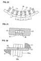
- Fig. 20 is an enlarged view of an essential section of the joint portions and the stator core of Fig. 19.
- Fig. 22 is a side sectional view of the joint portion of Fig. 21.
- Fig. 1 is a perspective view showing an essential section of a stator 30 of an automotive alternator according to First Embodiment of the present invention
- Fig. 2 is a top plan view showing a stator core and joint portions, in which the stator 30 of Fig. 1 is observed from a front bracket 1 side (joint portion side);
- Fig. 3 is an enlarged view of an essential section of the stator core and the joint portions shown in Fig. 2.
- a stator core 15 is shaped like a cylinder and has thirty-six slots 15a which have axes oriented in directions of grooves and are formed at equiangular pitches in a circumferential direction such that the slots 15a open on an inner peripheral side.
- a stator winding assembly 32 is constructed by a plurality of conductor segments 50 made of copper wires which are provided with insulating coating and virtually formed into U shapes, and installed in each slot 15a of the stator core 15 as shown in a winding diagram of Fig. 16.
- a connecting portion 53a extending to the front bracket 1 side from address 2 in the slot 15a of slot number 19 is slightly longer than a connecting portion 53b extending to the front bracket 1 side from address 1 in the slot 15a of slot number 22, which is three slots apart.
- a connecting portion 53a extending to the front bracket 1 side from address 4 in the slot 15a of slot number 19 is slightly shorter than a connecting portion 53b extending to the front bracket 1 side from address 3 in the slot 15a of slot number 22.
- the right and left connecting portions 53a and 53b of the U-shaped conductor segment 50 are formed to have different lengths so as to achieve a structure wherein an inner joint portion 32a and an outer joint portion 32b having distal ends of the connecting portions 53a and 53b joined by soldering are disposed such that they are shifted by half a slot in a circumferential direction as shown in Fig. 2 and Fig. 3.
- there are thirty-six slots 15a which are disposed at intervals of 10 degrees.
- the inner joint portion 32a and the outer joint portion 32b are shifted by 5 degrees, which is half the angle of the interval between the slots 15a.
- the connecting portions 53a and 53b of each conductor segment 50 are inserted in predetermined slots 15a from the rear bracket 2 side until they project toward the front bracket 1 as shown in Fig. 17. Thereafter, the connecting portions 53a and 53b are bent so that they are apart from each other in the circumferential direction, then the distal ends thereof are overlapped in the radial direction. At this time, the distal ends of the connecting portions 53a and 53b on the inner peripheral side of the conductor segment 50 and the distal ends of the connecting portions 53a and 53b on the outer peripheral side of the conductor segment 50 are shifted by half a slot in the circumferential direction. The distal ends are then wrapped with clamps 29 to be secured, and welded by soldering so as to form the inner joint portion 32a and the outer joint portion 32b.
- the inner joint portion 32a and the outer joint portion 32b are shifted by half a slot in the circumferential direction, so that they are disposed without overlapping each other in the radial direction.
- wrapping the clamps 29 can be easily wrapped around the connecting portions 53a and 53b, and chances for solder to undesirably cover adjacent joint portions 32a and 32b are minimized, thus permitting greater ease of connecting work and a higher yield.
- cooling air discharged from a centrifugal fan 5 more easily hits the connecting portions 53a and 53b of the conductor segments 50 on the outer peripheral side, leading to improved ability of cooling the stator winding assembly 32.
- the distal ends of the conductor segments 50 are joined by soldering.
- the distal ends of the conductor segments 50 are joined by soldering, and insulating varnish is further applied to the surfaces thereof to form an inner joint portion 33a and an outer joint portion 33b.
- the rest of the construction is the same as the construction of First Embodiment.
- a height of an inner joint portion 34a in an axial direction is set to be larger than that of an outer joint portion 34b as shown in Fig. 5.
- the rest of the construction is the same as the construction of Second Embodiment described above.
- a distance between the inner joint portion 34a and the outer joint portion 34b of a stator winding assembly 34 can be further increased; therefore, greater ease of welding and a higher yield can be improved, and a short circuit between the joint portions 34a and 34b attributable to vibration can be prevented.
- an inner joint portion 35a and an outer joint portion 35b are provided so that they incline in a direction of rotation of a rotor 7 with respect to a radial direction as shown in Fig. 6.
- the inner joint portion 35a and the outer joint portion 35b are slanted 30 degrees with respect to a radial line passing an axial center of a stator winding assembly 15.
- the rest of the construction of Fourth Embodiment is the same as the construction of Second Embodiment described above.
- the inclinations of the joint portions 35a and 35b substantially agree with a direction in which cooling air from a centrifugal fan 5 is discharged, permitting smooth exhaust of the cooling air.
- the joint portions are formed by solder welding. Obviously, however, the forming method of the joint portions is not limited thereto; the joint portions may be formed by TIG welding.
- connecting portions 53a and 53b overlapped in a radial direction are held by a pair of clamping jigs 40, and the distal ends of the connecting portions 53a and 53b are connected by TIG welding.
- an area of contact between the connecting portions 53a and 53b and the clamping jigs 40 is increased, allowing heat during welding to be transmitted to heat radiating jigs 41 via the clamping jigs 40 for quick heat radiation. This prevents occurrence of burning of coating in the vicinity of a joint portion of the connecting portions 53a and 53b during welding, allowing a good welding condition at the joint portion.
- an inner joint portion 36a and an outer joint portion 36b are disposed so that they are shifted by half a slot in a circumferential direction and have a gap A in a radial direction.
- the rest of the construction is identical to the construction of Second Embodiment described above.
- a larger gap can be secured between the inner joint portion 36a and the outer joint portion 36b as compared with Second Embodiment. This prevents adjacent joint portions 36a and 36b from being involved during TIG welding, permitting further greater ease of welding work and a still higher yield.
- Fig. 12 is a winding diagram of a stator 30E of an automotive alternator according to Sixth Embodiment of the present invention.
- Fig. 12 is the winding diagram of an a-phase stator winding member 161, and it does not show winding diagrams of a b-phase stator winding member and a c-phase stator winding member.
- solid lines denote conductors 100 connected to a rear bracket 2
- dotted lines denote conductors 100 connected to the front bracket 1.
- the stator winding members 161 for six phases are formed by shifting slots 15a, in which the conductors 100 are installed, by one slot, and the stator winding members 161 are star-connected for every three phases, thereby forming two sets of three-phase stator winding assemblies.
- a stator core 15A of the stator 30E is provided with 96 slots 15a equidistantly formed to accommodate the two sets of three-phase stator winding assemblies, corresponding to a number (16) of magnetic poles of a rotor 7.
- a stator winding assembly 101 is constituted by a plurality of winding members 161 wherein one conductor 100 is bent back outside a slot 15a on an end surface side of the stator core 15A and wave-wound such that it alternately passes an inner layer and an outer layer in a direction of slot depth in the slot 15a for every six slots.
- the conductor 100 led out to the front bracket 1 side from a first layer in each slot 15a is led into a second layer in the slot 15a located six slots away, and led out to the rear bracket 2 side, then led into the first layer in the slot 15a located another six slots away. Furthermore, the conductor 100 led out to the front bracket 1 side from a fourth layer is led into a third layer in the slot 15a located six slots away, and led out to the rear bracket 2 side, then led into the fourth layer in the slot 15a located another six slots away.
- the conductor 100 is formed of a copper wire provided with insulation coating.
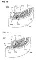
- Fig. 13 is a perspective view of an essential section of the stator 30E of Fig. 12 observed from the front bracket 1.
- a distal end B that extends in an axial direction of a first conductor portion 100a drawn out from the first layer in the slot 15a is continuously connected to the distal end B that extends in an axial direction of a second conductor portion 100b drawn out from the second layer in the slot 15a located six slots apart in a circumferential direction, the first and second conductor portions being formed of the continuous conductor 100.
- a distal end C that extends in an axial direction of the first conductor portion 100a drawn out from a third layer in the slot 15a is continuously connected to the distal end C that extends in an axial direction of a second conductor portion 100b drawn out from a fourth layer in the slot 15a located six slots apart in the circumferential direction, the first and second conductor portions being formed of the continuous conductor 100.
- the distal ends B and C are apart from each other by half the slot 15a in the circumferential direction.
- the distal ends B and C also serving as joint portions are apart from each other by half the slot 15a in the circumferential direction, not overlapping in the radial direction. Therefore, cooling air discharged from a fan 5 smoothly passes a coil end 101a of the stator winding assembly 101, so that the stator 30E is efficiently cooled to suppress a rise in temperature of the stator 30E.
- Fig. 14 is a perspective view of an essential section of a stator 30F (observed from a front bracket 1) of Seventh Embodiment in accordance with the present invention.
- a distal end D that extends in an axial direction of a first conductor portion 110a drawn out from a first layer in a slot 15a is continuously connected to the distal end D that extends in an axial direction of a second conductor portion 110b drawn out from a second layer in the slot 15a located six slots apart in a circumferential direction, the first and second conductor portions being formed of a continuous conductor 110.
- a distal end E that extends in an axial direction of the first conductor portion 110a drawn out from a third layer in the slot 15a is continuously connected to the distal end E that extends in an axial direction of the second conductor portion 110b drawn out from a fourth layer in the slot 15a located six slots apart in a circumferential direction, the two conductors being formed of the continuous conductor 110.
- the distal ends D and E are apart from each other by half the slot 15a in the circumferential direction, and the distal ends E on an inner peripheral side are higher than the distal ends D on an outer peripheral side.
- the distal ends D and E also serving as joint portions are apart from each other by half the slot 15a in the circumferential direction. Therefore, cooling air discharged from a fan 5 smoothly passes a coil end 111a of the stator winding assembly 111, so that the stator 30F is efficiently cooled to suppress a rise in temperature of the stator 30F.
- stator winding assemblies of the embodiments the 4-turn three-phase stator winding assemblies have been referred to.
- the number of turns may be increased to, for example, six or eight if a higher output at a lower speed is required.
- an outer joint portion where a distal end of a first conductor portion extending from a first layer of a first slot and a distal end of a second conductor portion extending from a second layer in a second slot are connected, and an inner joint portion where a distal end of a first conductor portion extending from a third layer of the first slot and a distal end of a second conductor portion extending from a fourth layer in the second slot are connected may bee spaced apart from each other by half a slot. Therefore, the joint portions on the inner peripheral side and the joint portions on the outer peripheral side are alternately disposed at equal intervals in the circumferential direction.
- the distal end of the first conductor portion and the distal end of the second conductor portion may overlap in the radial direction to form the joint portion. Therefore, the circumferential widths of the joint portions are small, so that larger gaps are provided between the joint portions adjoining in the circumferential direction. This arrangement increases the passing area of the cooling air generated by the rotation of the rotor, enabling the stator to be efficiently cooled.
- the joint portion may be inclined from a diameter of the stator in a direction of rotation of the rotor, and the joint portion may guide cooling air, which is generated by the rotation of the rotor, out of the stator core. Therefore, the alternator of this form allows the cooling air generated by the rotation of the rotor to be smoothly exhausted out of the stator, the stator can be efficiently cooled, and wind noises can be reduced.
- a gap may be provided in the radial direction between an inner joint portion located on an inner peripheral side of the stator core and an outer joint portion located on an outer peripheral side of the stator core. Therefore, the alternator of this form allows a larger radial gap to be secured between the outer joint portions and the inner portions. Hence, when the connecting work is performed by, for example, welding, greater ease of connection work and a higher yield can be achieved, and the occurrence of a short circuit attributable to vibration can be suppressed.
- the first conductor portion and the second conductor portion may form a substantially U-shaped conductor segment having leg ends bending away from each other, and the joint portions may be formed by joining the leg ends by welding. Therefore, the alternator of this form invention makes it possible to easily and securely connect the distal end extending in the axial direction of the first conductor portion drawn out from an n-th layer in a slot, to the distal end extending in the axial direction of the second conductor portion drawn out from an (n+1)th layer in a slot that is apart by a predetermined number of slots in the circumferential direction.
- the joint portion may be coated with an insulating resin. Therefore, the alternator of this form secures insulation of the joint portions and exhibits improved corrosion resistance to brine, etc.
- the first conductor portion and the second conductor portion may be formed of a continuous conductor, and be continuously connected in the joint portion. Therefore, the alternator of this form obviates the need for welding or other similar work for the joint portions, permitting easy fabrication of the stator winding assembly.
Landscapes
- Engineering & Computer Science (AREA)
- Power Engineering (AREA)
- Manufacturing & Machinery (AREA)
- Windings For Motors And Generators (AREA)
- Synchronous Machinery (AREA)
Priority Applications (1)
| Application Number | Priority Date | Filing Date | Title |
|---|---|---|---|
| EP03015538A EP1376819B1 (fr) | 2000-02-24 | 2000-09-07 | Alternateur |
Applications Claiming Priority (2)
| Application Number | Priority Date | Filing Date | Title |
|---|---|---|---|
| JP2000047795 | 2000-02-24 | ||
| JP2000047795A JP4318827B2 (ja) | 2000-02-24 | 2000-02-24 | 交流発電機 |
Related Child Applications (1)
| Application Number | Title | Priority Date | Filing Date |
|---|---|---|---|
| EP03015538A Division EP1376819B1 (fr) | 2000-02-24 | 2000-09-07 | Alternateur |
Publications (2)
| Publication Number | Publication Date |
|---|---|
| EP1128527A1 true EP1128527A1 (fr) | 2001-08-29 |
| EP1128527B1 EP1128527B1 (fr) | 2007-02-07 |
Family
ID=18569986
Family Applications (2)
| Application Number | Title | Priority Date | Filing Date |
|---|---|---|---|
| EP03015538A Expired - Lifetime EP1376819B1 (fr) | 2000-02-24 | 2000-09-07 | Alternateur |
| EP00119331A Expired - Lifetime EP1128527B1 (fr) | 2000-02-24 | 2000-09-07 | Générateur |
Family Applications Before (1)
| Application Number | Title | Priority Date | Filing Date |
|---|---|---|---|
| EP03015538A Expired - Lifetime EP1376819B1 (fr) | 2000-02-24 | 2000-09-07 | Alternateur |
Country Status (5)
| Country | Link |
|---|---|
| US (1) | US6448681B1 (fr) |
| EP (2) | EP1376819B1 (fr) |
| JP (1) | JP4318827B2 (fr) |
| KR (1) | KR100376919B1 (fr) |
| DE (1) | DE60033268T2 (fr) |
Cited By (11)
| Publication number | Priority date | Publication date | Assignee | Title |
|---|---|---|---|---|
| US6498414B2 (en) | 2000-08-29 | 2002-12-24 | Mitsubishi Denki Kabushiki Kaisha | Stator of dynamo-electric machine |
| EP1330011A1 (fr) * | 2002-01-07 | 2003-07-23 | Mitsubishi Denki Kabushiki Kaisha | Stator d'une machine dynamo-électrique |
| EP1376828A1 (fr) * | 2002-06-25 | 2004-01-02 | Denso Corporation | Bobinage avec segments conducteurs pour une machine électrique tournante avec forte isolation électrique |
| FR2845536A1 (fr) * | 2002-10-07 | 2004-04-09 | Valeo Equip Electr Moteur | Agencement de soudage des extremites libres de paires de segments de conducteurs electriques d'un bobinage d'une machine electrique tournante |
| WO2004034552A1 (fr) * | 2002-10-07 | 2004-04-22 | Valeo Equipements Electriques Moteur | Agencement de soudage des extremites de paires de segments de conducteurs electriques d'un bobinage d'une machine electrique tournante |
| CN1310406C (zh) * | 2002-10-07 | 2007-04-11 | 瓦莱奥电机设备公司 | 旋转电机绕组的成对导电片的自由端的焊接设备 |
| WO2007125010A1 (fr) * | 2006-04-26 | 2007-11-08 | Robert Bosch Gmbh | Procédé de fabrication d'un enroulement à cage d'écureuil pour le stator d'un moteur électrique |
| WO2009083327A1 (fr) * | 2007-12-27 | 2009-07-09 | Robert Bosch Gmbh | Machine électrique comprenant un stator muni d'un enroulement de stator et procédé de fabrication associé |
| CN102611233A (zh) * | 2011-01-19 | 2012-07-25 | 通用汽车环球科技运作有限责任公司 | 连接定子电线的方法和系统 |
| FR3020212A1 (fr) * | 2014-04-17 | 2015-10-23 | Valeo Equip Electr Moteur | Machine electrique tournante a refroidissement optimise |
| CN110771012A (zh) * | 2017-06-27 | 2020-02-07 | 日立汽车系统株式会社 | 旋转电机的定子以及旋转电机 |
Families Citing this family (25)
| Publication number | Priority date | Publication date | Assignee | Title |
|---|---|---|---|---|
| JP2003219617A (ja) * | 2002-01-21 | 2003-07-31 | Mitsubishi Electric Corp | 交流発電機 |
| JP3889630B2 (ja) * | 2002-01-21 | 2007-03-07 | 三菱電機株式会社 | 回転電機の巻線接合方法 |
| US6794785B2 (en) * | 2002-06-26 | 2004-09-21 | Denso Corporation | Alternator for vehicles |
| JP2004048890A (ja) * | 2002-07-11 | 2004-02-12 | Denso Corp | 回転電機 |
| JP4606746B2 (ja) * | 2004-01-29 | 2011-01-05 | 三菱電機株式会社 | 交流発電機 |
| JP2006271015A (ja) * | 2005-03-22 | 2006-10-05 | Denso Corp | 車両用交流発電機 |
| JP4501762B2 (ja) * | 2005-04-18 | 2010-07-14 | 株式会社デンソー | 車両用交流発電機 |
| JP2007037280A (ja) * | 2005-07-27 | 2007-02-08 | Mitsubishi Electric Corp | インバータ一体型回転電機 |
| JP5453770B2 (ja) | 2008-11-07 | 2014-03-26 | 株式会社デンソー | 回転電機の固定子およびその製造方法 |
| US8436506B2 (en) | 2010-04-13 | 2013-05-07 | GM Global Technology Operations LLC | Electric motor assemblies and systems and methods associated with joining wires of electric motor assemblies |
| US8671559B2 (en) * | 2011-04-27 | 2014-03-18 | GM Global Technology Operations LLC | System for joining stator wires |
| JP2013005516A (ja) | 2011-06-14 | 2013-01-07 | Toyota Motor Corp | ステータおよび回転電機 |
| US20130106231A1 (en) * | 2011-10-27 | 2013-05-02 | Remy Technologies, L.L.C. | Conductor weld-end length control forming |
| JP5585657B2 (ja) * | 2011-12-28 | 2014-09-10 | トヨタ自動車株式会社 | 回転電機及び固定子製造方法 |
| US9757820B2 (en) * | 2012-05-24 | 2017-09-12 | GM Global Technology Operations LLC | Welding fixture for joining bar-wound stator conductors |
| KR101365469B1 (ko) * | 2012-09-20 | 2014-02-25 | 현대모비스 주식회사 | 헤어핀 접속기구 및 이를 구비한 헤어핀 권선모터 |
| CN106575895B (zh) * | 2014-09-19 | 2018-11-30 | 三菱电机株式会社 | 定子以及使用了该定子的旋转电机 |
| JP6577428B2 (ja) * | 2016-08-26 | 2019-09-18 | トヨタ自動車株式会社 | モータの製造装置 |
| CN109923771B (zh) * | 2016-11-18 | 2022-10-04 | 日立安斯泰莫株式会社 | 定子的制造方法 |
| DE102017116973A1 (de) * | 2017-07-27 | 2019-01-31 | Strama-Mps Maschinenbau Gmbh & Co. Kg | Verfahren und Vorrichtung zum Bearbeiten von Leitersegmenten eines Wicklungsträgers einer elektrischen Maschine |
| KR102528420B1 (ko) * | 2017-12-15 | 2023-05-03 | 현대모비스 주식회사 | 헤어핀 권선모터의 고정자 코일 절연구조 |
| KR102214059B1 (ko) | 2018-11-28 | 2021-02-08 | 한국토지주택공사 | 중앙부에 충격완화층을 갖는 슬래브의 층간소음 방지구조 |
| JP2020141528A (ja) * | 2019-02-28 | 2020-09-03 | 日本電産株式会社 | コイル接合方法、ステータ、それを備えたモータ及びそのモータを搭載した車両 |
| KR102338176B1 (ko) | 2019-10-21 | 2021-12-09 | 삼성물산(주) | 바닥부 중량충격음 저감을 위한 마감천장구조 |
| DE102020119587A1 (de) * | 2020-07-24 | 2022-01-27 | Pro-Beam Gmbh & Co. Kgaa | Positioniervorrichtung und Verfahren zum Positionieren von Drahtenden bei der Herstellung einer elektrischen Maschine |
Citations (4)
| Publication number | Priority date | Publication date | Assignee | Title |
|---|---|---|---|---|
| JPS57132743A (en) * | 1981-02-09 | 1982-08-17 | Nippon Denso Co Ltd | Ac generator for vehicle |
| EP0881750A2 (fr) * | 1997-05-26 | 1998-12-02 | Denso Corporation | Alternateur pour véhicule automobile |
| EP0923187A2 (fr) * | 1997-12-10 | 1999-06-16 | Denso Corporation | Alternateur de véhicule automobile |
| JP2000166150A (ja) * | 1998-11-26 | 2000-06-16 | Denso Corp | 車両用交流発電機の固定子 |
Family Cites Families (15)
| Publication number | Priority date | Publication date | Assignee | Title |
|---|---|---|---|---|
| JPS5264602A (en) * | 1975-11-26 | 1977-05-28 | Hitachi Ltd | Process of insulation treatment of electric winding |
| JPS576551A (en) * | 1980-06-12 | 1982-01-13 | Nippon Denso Co Ltd | Ac generator for vehicle |
| JPS59159638A (ja) * | 1983-03-01 | 1984-09-10 | Nippon Denso Co Ltd | 車両用交流発電機 |
| JPH0412637Y2 (fr) * | 1986-09-14 | 1992-03-26 | ||
| JPS6392237A (ja) * | 1986-10-03 | 1988-04-22 | Hitachi Ltd | 回転電機の固定子巻線 |
| JP3561927B2 (ja) * | 1993-07-28 | 2004-09-08 | 株式会社デンソー | 車両用交流発電機 |
| WO1998040953A1 (fr) * | 1997-03-10 | 1998-09-17 | Denso Corporation | Alternateur pour vehicule |
| JP3271582B2 (ja) * | 1997-05-26 | 2002-04-02 | 株式会社デンソー | 車両用交流発電機 |
| JP3438570B2 (ja) * | 1997-05-26 | 2003-08-18 | 株式会社デンソー | 車両用交流発電機 |
| JP3456140B2 (ja) * | 1997-05-26 | 2003-10-14 | 株式会社デンソー | 車両用交流発電機 |
| EP1237254B1 (fr) * | 1997-05-26 | 2008-06-04 | Denso Corporation | Alternateur pour véhicules automobiles |
| JP3855453B2 (ja) * | 1997-05-26 | 2006-12-13 | 株式会社デンソー | 車両用交流発電機 |
| JP3744184B2 (ja) * | 1997-05-26 | 2006-02-08 | 株式会社デンソー | 車両用交流発電機 |
| JP3724951B2 (ja) | 1998-05-25 | 2005-12-07 | 株式会社デンソー | 車両用交流発電機 |
| EP0961384B1 (fr) * | 1998-05-25 | 2005-02-09 | Denso Corporation | Alternateur pour véhicule et procédé de sa fabrication |
-
2000
- 2000-02-24 JP JP2000047795A patent/JP4318827B2/ja not_active Expired - Lifetime
- 2000-09-07 EP EP03015538A patent/EP1376819B1/fr not_active Expired - Lifetime
- 2000-09-07 DE DE60033268T patent/DE60033268T2/de not_active Expired - Lifetime
- 2000-09-07 EP EP00119331A patent/EP1128527B1/fr not_active Expired - Lifetime
- 2000-09-19 US US09/664,744 patent/US6448681B1/en not_active Expired - Lifetime
- 2000-11-24 KR KR10-2000-0070250A patent/KR100376919B1/ko not_active Expired - Fee Related
Patent Citations (4)
| Publication number | Priority date | Publication date | Assignee | Title |
|---|---|---|---|---|
| JPS57132743A (en) * | 1981-02-09 | 1982-08-17 | Nippon Denso Co Ltd | Ac generator for vehicle |
| EP0881750A2 (fr) * | 1997-05-26 | 1998-12-02 | Denso Corporation | Alternateur pour véhicule automobile |
| EP0923187A2 (fr) * | 1997-12-10 | 1999-06-16 | Denso Corporation | Alternateur de véhicule automobile |
| JP2000166150A (ja) * | 1998-11-26 | 2000-06-16 | Denso Corp | 車両用交流発電機の固定子 |
Non-Patent Citations (2)
| Title |
|---|
| PATENT ABSTRACTS OF JAPAN vol. 006, no. 230 (E - 142) 16 November 1982 (1982-11-16) * |
| PATENT ABSTRACTS OF JAPAN vol. 2000, no. 09 13 October 2000 (2000-10-13) * |
Cited By (14)
| Publication number | Priority date | Publication date | Assignee | Title |
|---|---|---|---|---|
| US6498414B2 (en) | 2000-08-29 | 2002-12-24 | Mitsubishi Denki Kabushiki Kaisha | Stator of dynamo-electric machine |
| EP1330011A1 (fr) * | 2002-01-07 | 2003-07-23 | Mitsubishi Denki Kabushiki Kaisha | Stator d'une machine dynamo-électrique |
| US6833648B2 (en) | 2002-06-25 | 2004-12-21 | Denso Corporation | Sequentially joined-segment coil for rotary electrical machine with high degree of electrical insulation |
| EP1376828A1 (fr) * | 2002-06-25 | 2004-01-02 | Denso Corporation | Bobinage avec segments conducteurs pour une machine électrique tournante avec forte isolation électrique |
| CN1310406C (zh) * | 2002-10-07 | 2007-04-11 | 瓦莱奥电机设备公司 | 旋转电机绕组的成对导电片的自由端的焊接设备 |
| WO2004034552A1 (fr) * | 2002-10-07 | 2004-04-22 | Valeo Equipements Electriques Moteur | Agencement de soudage des extremites de paires de segments de conducteurs electriques d'un bobinage d'une machine electrique tournante |
| FR2845536A1 (fr) * | 2002-10-07 | 2004-04-09 | Valeo Equip Electr Moteur | Agencement de soudage des extremites libres de paires de segments de conducteurs electriques d'un bobinage d'une machine electrique tournante |
| WO2007125010A1 (fr) * | 2006-04-26 | 2007-11-08 | Robert Bosch Gmbh | Procédé de fabrication d'un enroulement à cage d'écureuil pour le stator d'un moteur électrique |
| US8584346B2 (en) | 2006-04-26 | 2013-11-19 | Robert Bosch Gmbh | Method for producing a bar winding for the stator of an electric machine |
| WO2009083327A1 (fr) * | 2007-12-27 | 2009-07-09 | Robert Bosch Gmbh | Machine électrique comprenant un stator muni d'un enroulement de stator et procédé de fabrication associé |
| CN102611233A (zh) * | 2011-01-19 | 2012-07-25 | 通用汽车环球科技运作有限责任公司 | 连接定子电线的方法和系统 |
| FR3020212A1 (fr) * | 2014-04-17 | 2015-10-23 | Valeo Equip Electr Moteur | Machine electrique tournante a refroidissement optimise |
| CN110771012A (zh) * | 2017-06-27 | 2020-02-07 | 日立汽车系统株式会社 | 旋转电机的定子以及旋转电机 |
| CN110771012B (zh) * | 2017-06-27 | 2021-07-27 | 日立汽车系统株式会社 | 旋转电机的定子以及旋转电机 |
Also Published As
| Publication number | Publication date |
|---|---|
| KR20010085257A (ko) | 2001-09-07 |
| DE60033268T2 (de) | 2007-10-25 |
| EP1376819B1 (fr) | 2011-08-03 |
| KR100376919B1 (ko) | 2003-03-26 |
| DE60033268D1 (de) | 2007-03-22 |
| EP1128527B1 (fr) | 2007-02-07 |
| EP1376819A3 (fr) | 2008-08-20 |
| JP2001238386A (ja) | 2001-08-31 |
| JP4318827B2 (ja) | 2009-08-26 |
| US6448681B1 (en) | 2002-09-10 |
| EP1376819A2 (fr) | 2004-01-02 |
Similar Documents
| Publication | Publication Date | Title |
|---|---|---|
| EP1128527B1 (fr) | Générateur | |
| JP3347118B2 (ja) | 交流発電機 | |
| JP4014071B2 (ja) | 交流発電機及びその巻線アッセンブリ並びに巻線アッセンブリの製造方法 | |
| US6498414B2 (en) | Stator of dynamo-electric machine | |
| EP1179880B1 (fr) | Machine dynamo-électrique | |
| KR100396800B1 (ko) | 교류발전기 | |
| JP3155532B1 (ja) | 車両用交流発電機の固定子 | |
| US6501204B1 (en) | Stator for an alternator | |
| KR100414320B1 (ko) | 회전전기 | |
| JPWO2005107040A1 (ja) | 回転電機 | |
| JP4162081B2 (ja) | 車両用交流発電機 | |
| JP3894411B2 (ja) | 車両用交流発電機 | |
| JP3566665B2 (ja) | 回転電機の固定子 | |
| JP2002218687A (ja) | 車両用交流発電機 | |
| JP3502589B2 (ja) | 交流発電機 | |
| JP4437671B2 (ja) | 交流発電機 | |
| JP4468411B2 (ja) | 交流発電機 | |
| JP4906909B2 (ja) | 車両用交流発電機 | |
| JP4606746B2 (ja) | 交流発電機 | |
| JP4468412B2 (ja) | 交流発電機 | |
| JP4362145B2 (ja) | 交流発電機 | |
| KR100576227B1 (ko) | 차량용 교류발전기 | |
| EP1330011B1 (fr) | Stator d'une machine dynamo-électrique |
Legal Events
| Date | Code | Title | Description |
|---|---|---|---|
| PUAI | Public reference made under article 153(3) epc to a published international application that has entered the european phase |
Free format text: ORIGINAL CODE: 0009012 |
|
| 17P | Request for examination filed |
Effective date: 20010410 |
|
| AK | Designated contracting states |
Kind code of ref document: A1 Designated state(s): DE FR GB Kind code of ref document: A1 Designated state(s): AT BE CH CY DE DK ES FI FR GB GR IE IT LI LU MC NL PT SE |
|
| AX | Request for extension of the european patent |
Free format text: AL;LT;LV;MK;RO;SI |
|
| 17Q | First examination report despatched |
Effective date: 20011219 |
|
| AKX | Designation fees paid |
Free format text: DE FR GB |
|
| RAP1 | Party data changed (applicant data changed or rights of an application transferred) |
Owner name: MITSUBISHI DENKI KABUSHIKI KAISHA |
|
| GRAP | Despatch of communication of intention to grant a patent |
Free format text: ORIGINAL CODE: EPIDOSNIGR1 |
|
| GRAS | Grant fee paid |
Free format text: ORIGINAL CODE: EPIDOSNIGR3 |
|
| GRAA | (expected) grant |
Free format text: ORIGINAL CODE: 0009210 |
|
| AK | Designated contracting states |
Kind code of ref document: B1 Designated state(s): DE FR GB |
|
| REG | Reference to a national code |
Ref country code: GB Ref legal event code: FG4D |
|
| REF | Corresponds to: |
Ref document number: 60033268 Country of ref document: DE Date of ref document: 20070322 Kind code of ref document: P |
|
| ET | Fr: translation filed | ||
| REG | Reference to a national code |
Ref country code: GB Ref legal event code: 727 |
|
| REG | Reference to a national code |
Ref country code: GB Ref legal event code: 727A |
|
| PLBE | No opposition filed within time limit |
Free format text: ORIGINAL CODE: 0009261 |
|
| STAA | Information on the status of an ep patent application or granted ep patent |
Free format text: STATUS: NO OPPOSITION FILED WITHIN TIME LIMIT |
|
| 26N | No opposition filed |
Effective date: 20071108 |
|
| REG | Reference to a national code |
Ref country code: GB Ref legal event code: 727B |
|
| PGFP | Annual fee paid to national office [announced via postgrant information from national office to epo] |
Ref country code: FR Payment date: 20100921 Year of fee payment: 11 |
|
| PGFP | Annual fee paid to national office [announced via postgrant information from national office to epo] |
Ref country code: GB Payment date: 20100901 Year of fee payment: 11 |
|
| PGFP | Annual fee paid to national office [announced via postgrant information from national office to epo] |
Ref country code: DE Payment date: 20100901 Year of fee payment: 11 |
|
| GBPC | Gb: european patent ceased through non-payment of renewal fee |
Effective date: 20110907 |
|
| REG | Reference to a national code |
Ref country code: FR Ref legal event code: ST Effective date: 20120531 |
|
| REG | Reference to a national code |
Ref country code: DE Ref legal event code: R119 Ref document number: 60033268 Country of ref document: DE Effective date: 20120403 |
|
| PG25 | Lapsed in a contracting state [announced via postgrant information from national office to epo] |
Ref country code: DE Free format text: LAPSE BECAUSE OF NON-PAYMENT OF DUE FEES Effective date: 20120403 |
|
| PG25 | Lapsed in a contracting state [announced via postgrant information from national office to epo] |
Ref country code: GB Free format text: LAPSE BECAUSE OF NON-PAYMENT OF DUE FEES Effective date: 20110907 Ref country code: FR Free format text: LAPSE BECAUSE OF NON-PAYMENT OF DUE FEES Effective date: 20110930 |