EP1128542A1 - Moteur série freiné - Google Patents
Moteur série freiné Download PDFInfo
- Publication number
- EP1128542A1 EP1128542A1 EP01103944A EP01103944A EP1128542A1 EP 1128542 A1 EP1128542 A1 EP 1128542A1 EP 01103944 A EP01103944 A EP 01103944A EP 01103944 A EP01103944 A EP 01103944A EP 1128542 A1 EP1128542 A1 EP 1128542A1
- Authority
- EP
- European Patent Office
- Prior art keywords
- coil
- field
- field coil
- motor according
- pole
- Prior art date
- Legal status (The legal status is an assumption and is not a legal conclusion. Google has not performed a legal analysis and makes no representation as to the accuracy of the status listed.)
- Granted
Links
- 230000005669 field effect Effects 0.000 claims description 31
- 238000004804 winding Methods 0.000 claims description 21
- 230000007935 neutral effect Effects 0.000 claims description 8
- 210000002105 tongue Anatomy 0.000 claims description 6
- 230000001419 dependent effect Effects 0.000 claims description 2
- 230000005611 electricity Effects 0.000 claims description 2
- 230000002093 peripheral effect Effects 0.000 abstract 2
- 238000000034 method Methods 0.000 description 6
- 230000002441 reversible effect Effects 0.000 description 4
- 238000010586 diagram Methods 0.000 description 3
- 230000000694 effects Effects 0.000 description 3
- 230000000977 initiatory effect Effects 0.000 description 3
- 230000000903 blocking effect Effects 0.000 description 2
- 230000001105 regulatory effect Effects 0.000 description 2
- 238000004904 shortening Methods 0.000 description 2
- OKTJSMMVPCPJKN-UHFFFAOYSA-N Carbon Chemical compound [C] OKTJSMMVPCPJKN-UHFFFAOYSA-N 0.000 description 1
- 238000010521 absorption reaction Methods 0.000 description 1
- 230000002411 adverse Effects 0.000 description 1
- 229910052799 carbon Inorganic materials 0.000 description 1
- 230000002349 favourable effect Effects 0.000 description 1
- 230000004048 modification Effects 0.000 description 1
- 238000012986 modification Methods 0.000 description 1
- 230000000630 rising effect Effects 0.000 description 1
- 238000004513 sizing Methods 0.000 description 1
- 230000001629 suppression Effects 0.000 description 1
Images


Classifications
-
- H—ELECTRICITY
- H02—GENERATION; CONVERSION OR DISTRIBUTION OF ELECTRIC POWER
- H02P—CONTROL OR REGULATION OF ELECTRIC MOTORS, ELECTRIC GENERATORS OR DYNAMO-ELECTRIC CONVERTERS; CONTROLLING TRANSFORMERS, REACTORS OR CHOKE COILS
- H02P3/00—Arrangements for stopping or slowing electric motors, generators, or dynamo-electric converters
- H02P3/06—Arrangements for stopping or slowing electric motors, generators, or dynamo-electric converters for stopping or slowing an individual dynamo-electric motor or dynamo-electric converter
-
- H—ELECTRICITY
- H02—GENERATION; CONVERSION OR DISTRIBUTION OF ELECTRIC POWER
- H02K—DYNAMO-ELECTRIC MACHINES
- H02K1/00—Details of the magnetic circuit
- H02K1/06—Details of the magnetic circuit characterised by the shape, form or construction
- H02K1/12—Stationary parts of the magnetic circuit
- H02K1/14—Stator cores with salient poles
- H02K1/146—Stator cores with salient poles consisting of a generally annular yoke with salient poles
- H02K1/148—Sectional cores
Definitions
- the invention relates in particular to a braked series motor Universal motor for a power tool, with an anchor with a commutating armature coil that is in a stand is rotatably mounted and fed by brushes, with at least two field poles, each a pole horn with one leading edge and a pole horn with a trailing edge has, with a field coil, and with a switching device for switching between engine operation and braking operation, whereby in motor operation, the field coil with the armature coil in one of a supply voltage to the motor circuit in Series is connected, and the field coil in braking mode with the armature coil a closed and from the supply voltage separate brake circuit forms.
- Such a series motor is from DE 196 36 519 C1 known.
- the known motor is a universal motor with a pole pack with field pole arrangements each consisting of two pole parts, wherein the pole pack is designed for a predetermined direction of rotation and a circuit arrangement is assigned to the motor is the one between engine and brake operation with one Current path containing diode arrangement parallel to the field coil includes.
- a field auxiliary coil is provided, which in a specially designed Pole sheet package on the running edge of the two pole horns wraps around the field coil and separately on the leading edge is recorded on the pole horns.
- commutation is usually used for universal motors the armature coil opposite the geometrically neutral zone the running direction. This is usually done by that the carbon brushes against the direction of rotation of the armature be moved out of the neutral zone. In this way a reduced brush fire is achieved without reversing pole windings are necessary. Should a universal motor designed in this way are braked by the armature coil or the Field coil reversed by means of a changeover switch and the motor is short-circuited, it results during the braking phase of Motors have poor commutation if no brush adjustment is made or no reversing poles are provided.
- the invention is therefore based on the object of an improved braked series motor to create a sufficient ensures good commutation in motor operation and in which a too strong brush fire avoided during braking becomes. Additional windings should be avoided as far as possible can be.
- This task is in a series motor according to the entry mentioned type in that the polar horns with expiring Edge opposite the pole horns with a tapered edge seen in the circumferential direction are shortened or at least one have recess extending in the circumferential direction.
- the Polar horns an increased concentration of magnetic field lines, while this is on the rising side in engine operation the pole horns are done.
- the draining side or by using recesses becomes the brush fire intensified in the engine operating phase counteracted by the unfavorable arrangement of the brushes.
- the expiring Edges of the pole horns each have at least two in the circumferential direction extending tongues provided between which the at least one recess is formed.
- the commutating armature coil is preferred against the geometrically neutral zone against the Running direction changed.
- means for limiting the im are preferably Brake operation flowing brake current provided.
- a network-powered one Transformer provided, the secondary winding in Brake circuit is connected in parallel to the field coil, whereby a controlled switch, preferably a transistor, for Control of the in the brake circuit via the armature coil and Field coil flowing current is provided.
- the controlled switch is the Invention designed as a field effect transistor with the source and drain connected in parallel to the field coil via a diode and the current through the field coil depending on regulates current flowing through the armature coil.
- the secondary winding a current is introduced into the brake circuit by the transformer, which is a reliable initiation of braking in everyone Trap guaranteed. This way even in extremely unfavorable Cases a safe initiation of braking when switching ensured in braking mode. This is done by enables the field effect transistor to readjust the braking current, so that even when the braking process continues strong braking torque is available. This allows significantly improve the braking characteristics to a short Ensure braking time. The braking characteristics can be adjust so that the motor coasts down slowly End of braking is avoided.
- the field effect transistor is preferably with its Gate via a voltage divider to the brushes and thus connected to the armature coil.
- a rectifier circuit which is preferably is a bridge rectifier, parallel to the field coil coupled, again a controlled switch, preferably a transistor to control the in the brake circuit the armature coil and the field coil flowing current are provided is.
- the controlled switch is preferably a field effect transistor trained in parallel with source and drain in braking is coupled to the field coil and the current through the Field coil depending on the flowing over the armature coil Electricity regulates.
- the field effect transistor is preferred in braking operation with source connected directly to one end of the field coil and with drain across a resistor to the other end connected to the field coil.
- the secondary winding in the brake circuit via a bridge rectifier connected in parallel to the field coil, whereby the positive pole of the bridge rectifier with drain and the negative pole of the bridge rectifier coupled to the source of the field effect transistor is.
- a load resistor in the brake circuit provided between a brush and one end of the field coil is connected via the diode, being at one end of the Load resistance of the field effect transistor connected with drain is, and wherein the field effect transistor with source with the connected to the other brush and the other end of the field winding is.
- a series-wound motor according to the invention is generally designated by the number 10 in FIG. 1.
- the motor 10 comprises an armature with an armature coil 12 which can be connected in series with a supply voltage source 22 via a switch S 0 in motor operation via a switch S 0, not shown, and only schematically indicated brushes 17, 18 which supplies an alternating voltage of 230 volts.
- Switch S 0 is a two-pole switch with a first switch S 1 and a second switch S 2 .
- the first pole of the supply voltage source 22 is connected via a line 56 to a first changeover contact 46 of the first changeover switch S 1, which is connected to the contact 44 when the switch S 1 is closed and is in turn coupled to a brush 17 via a line 57.
- the second brush 18 is connected via a line 58 to two contacts 50, 52 of the second changeover switch S 2 connected to one another in motor operation, the contact 52 being connected via a line 64 to a first end of the two-part field coil 14, 16.
- the field coil has a first coil part 14 and a second coil part 16, which are in series with one another, the end of the second coil part 16 being connected to the second pole 23 of the supply voltage source 22 via control electronics 36.
- the control electronics 36 is additionally coupled via a control line 60 to the first pole 21 of the supply voltage source 22 and via a control line 61 to the contacts 44 and 45 of the first changeover switch S 1 .
- the control electronics 36 serve to limit the starting current when the motor is switched on, to limit the idling speed of the motor and prevent the motor from starting if a plug is inserted for connection to the supply voltage source 22 while the switch S 0 is in the switched-on position .
- This known control electronics 36 is connected to the second coil part 16 of the field coil, while the other coil part 14, as already mentioned, via the switch S 0 in motor operation via the line 64 and the contacts 50, 52 of the second switch S 2 with the Brush 18 is coupled. This arrangement facilitates interference suppression of the series motor 10.
- the contacts 44, 46 of the first switch S 1 are open, while the further contacts 45, 47 of the first switch S 1 are closed.
- the contacts 50, 52 of the second switch S 2 are open in braking operation, while the contacts 51, 53 of the second switch S 2 are closed.
- an anti-parallel diode path 55 is connected, which is connected via a line 65 to the contact 50 and via a line 63 to the contact 47 of the first switch S 1 and the end of the first coil part 14 is coupled.
- FIG. 2 now shows the structure of a stator 80 according to the invention.
- the stator 80 is preferably composed of two halves 82, 84, as is known in detail from DE 195 07 264 A1 is. This will assemble the coil parts of the field windings relieved on the stator 80.
- the two halves 82, 84 become 100 after the winding packages have been assembled through pins 86, 88 inserted into corresponding openings are firmly connected to each other, so that the stator 80 as closed annular yoke is formed.
- the stator 80 has a first field pole 90 and a second, opposite field pole 110.
- Each of the two field poles 90, 110 has two pole horns 92, 96 and 112, 116, respectively.
- the preferred one Direction of rotation of the motor is indicated at 126. So owns the first field pole 90 is a pole horn 92 with a leading edge 94 and a pole horn 96 with a running edge 98.
- the second field pole 110 has a pole horn 112 with an increasing Edge 114 and a pole horn 116 with a running edge 118.
- 3 shows a view of the first field pole 90 from the inside, which is shown in a flat development.
- pole horn 92 on the side of the leading edge 94 in the usual manner in a known manner from the locations of the Sheet packets massive, i.e. without recesses, has the pole horn 96 on the side of the trailing edge 98 recess extending in the axial direction of the stator 80 102 on each of the two axial ends of the pole horn 96 by a tongue 104 protruding in the circumferential direction, 106 is included.
- the pole horns 92 and 96 are basically symmetrical to each other constructed, with only the Polhorn 96 on the expiring Edge 98 is shortened in the circumferential direction by the recess 102 is, while the extension of the tongues 104, 106 the outline of the other pole horn 92 corresponds.
- the other of the pole horns 116 a corresponding recess is provided in the second field pole 110, which is only indicated in FIG. 2 with the number 122.
- Fig. 2 is also the geometrically neutral zone with the Line 124 indicated.
- the brushes 17, 18 of the series motor 10 are shifted against the direction of rotation 126 by an angle ⁇ arranged, as it is in such universal motors is basically known to the commutation in motor operation to improve and reduce the brush fire.
- tongues 104, 106 and the recess 102 of FIG. 3 are merely exemplary in nature. So can further and differently shaped tongues may be provided. Can too Shape and arrangement of the recess or recesses in each case the draining side of the pole horns can be varied.
- the basic structure of the circuit corresponds to the version 1, with only switched to the anti-parallel Diode section 55 was dispensed with and instead a transformer 26 is provided in connection with a Field effect transistor circuit.
- the transformer 26 has its primary side 28 directly connected to the two poles 21, 23 of the supply voltage source 22. With its secondary side 30, the transformer 26 is connected via a diode 38 to one end of the first field coil part 14 and at its other end via a line 59 to the contact 50 of the second changeover switch S 2 or to the line 58, which leads to Brush 18 of the armature coil 12 leads. As can be seen in FIG. 4, in braking operation the brush 18 is also connected to the end of the second coil part 16 of the field coil via the line 58 and the contacts 50, 51, 53 of the second changeover switch S 2 and the line 62.
- a field effect transistor 42 of the IRF 540 type is coupled to drain D via a diode 48 to the end of the first coil part 14 and thus likewise to the diode 38. Both diodes 38, 48 lie together with their cathodes at the end of the first coil part 14.
- the field effect transistor 42 is connected to the source S via the line 59 to the contact 50 of the second switch S 2 and thus via the line 58 to the brush 18 Armature coil 12 coupled.
- the anode of the diode 48 is connected via a load resistor 20 to the contact 47 of the first changeover switch S 2 , which in the braking position shown is connected via the contacts 45, 44 to the line 57 which leads to the brush 17.
- the field effect transistor 42 is connected with its gate G via a voltage divider 70, 72, which consists of a first resistor 70, which can be, for example, one kiloohm, and a second resistor 72, which can be, for example, 6 kiloohms.
- the resistor 70 has one end connected to the contact 47 of the switch S 1 and the other end connected to the resistor 72, which is connected to the contact 50 of the switch S 2 .
- the gate G of the field effect transistor is connected between the two resistors 70, 72.
- a Zener diode could also be provided, which generates the desired switching voltage.
- the field effect transistor 42 is at its gate G via the Voltage divider 70, 72 driven, from which the voltage at the Connection of the resistors 70, 72 is tapped.
- the field effect transistor is in braking mode 42 the field current is regulated and the armature voltage kept approximately constant during the braking process until this finally collapses at the end of braking.
- the sizing can be about 2000 watts for a motor Power consumption at 230 volts AC designed in this way be that the transformer for a secondary voltage of 4 volts is designed for a power of 0.25 watts, whereby can be used as the field effect transistor 42 of the MOSFET IRF540 can for a maximum current of 28 A and a maximum Power loss of 125 watts is designed.
- a load resistance 20 can have a resistance of 0.33 ohms at a maximum Power dissipation of 10 watts can be used, and the voltage divider can, as already mentioned, from the two resistors 70 out of 1 kiloohm and 72 out of 6 kiloohm exist.
- the field effect transistor 42 begins during the braking process to conduct when a voltage of between gate G and source S. about 4 volts across the voltage divider 70, 72. Since on Load resistor 20 is a voltage that depends on the size of the current flowing through the armature coil 12 is dependent in this version the armature voltage during the braking process kept largely constant and the field current from the field effect transistor 42 regulated.
- the armature voltage drops so much that the field effect transistor 42 goes into the blocking state, whereby the field current flowing through the field coil 14, 16 briefly rises again so that the braking process increases its end is reinforced.
- Such a design is particularly for one braked Angle grinder with a high power consumption of around 2000 Watt advantageous because it has a particularly favorable braking characteristic generated.
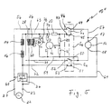
- FIG. 5 shows a further modification of the circuit according to FIG. 4, in which a series motor with the Number 10 ''.
- the basic structure of the circuit corresponds to the version 4, with only the diodes 38 and 48th was dispensed with and instead the secondary winding 30 of Transformer 26 via a bridge rectifier circuit 76 with the line 63, which is connected to the field coil 14, on the one hand, and with the source of the field effect transistor 42 on the other hand connected is.
- Resistor 20 is now immediate with the field coil 14 and the positive pole of the bridge rectifier 76 connected.
- the negative pole of the bridge rectifier 76 is immediate connected to the source of the field effect transistor 42.
- in deviation from the circuit shown in FIG. 4 is between Drain the field effect transistor 42 and the end of the load resistor 20 or the field coil 14 is now a resistor 74 provided that with otherwise the same design as before could be 0.15 ohms.
- the bridge rectifier 76 in conjunction with a switch S 0 designed in this way clearly predetermines the direction of self-excitation at any time during the braking phase.
Landscapes
- Engineering & Computer Science (AREA)
- Power Engineering (AREA)
- Stopping Of Electric Motors (AREA)
- Control Of Direct Current Motors (AREA)
Priority Applications (1)
| Application Number | Priority Date | Filing Date | Title |
|---|---|---|---|
| EP20010103944 EP1128542B1 (fr) | 2000-02-25 | 2001-02-19 | Moteur série freiné |
Applications Claiming Priority (5)
| Application Number | Priority Date | Filing Date | Title |
|---|---|---|---|
| EP00103957A EP1045511B1 (fr) | 1999-03-18 | 2000-02-25 | Moteur série |
| EP00103957 | 2000-02-25 | ||
| DE10032039A DE10032039A1 (de) | 2000-07-05 | 2000-07-05 | Gebremster Reihenschlußmotor |
| DE10032039 | 2000-07-05 | ||
| EP20010103944 EP1128542B1 (fr) | 2000-02-25 | 2001-02-19 | Moteur série freiné |
Publications (2)
| Publication Number | Publication Date |
|---|---|
| EP1128542A1 true EP1128542A1 (fr) | 2001-08-29 |
| EP1128542B1 EP1128542B1 (fr) | 2010-12-29 |
Family
ID=27213937
Family Applications (1)
| Application Number | Title | Priority Date | Filing Date |
|---|---|---|---|
| EP20010103944 Expired - Lifetime EP1128542B1 (fr) | 2000-02-25 | 2001-02-19 | Moteur série freiné |
Country Status (1)
| Country | Link |
|---|---|
| EP (1) | EP1128542B1 (fr) |
Cited By (1)
| Publication number | Priority date | Publication date | Assignee | Title |
|---|---|---|---|---|
| DE10209010A1 (de) * | 2002-02-26 | 2003-09-04 | C & E Fein Gmbh & Co Kg | Reihenschlußmotor |
Citations (6)
| Publication number | Priority date | Publication date | Assignee | Title |
|---|---|---|---|---|
| US4144482A (en) * | 1977-04-07 | 1979-03-13 | Beckman Instruments, Inc. | Dynamic brake circuit for motor |
| DE3636555A1 (de) * | 1986-10-28 | 1988-05-11 | Schroecker Rainer | Schaltungsanordnung zum bremsen eines kollektormotors |
| WO1991003866A1 (fr) * | 1989-09-06 | 1991-03-21 | Hans Hermann Rottmerhusen | Moteur a collecteur |
| DE4201023A1 (de) * | 1992-01-16 | 1993-07-22 | Schroecker Rainer | Aussetzerfreie bremsschaltung fuer universalmotoren |
| DE4333733A1 (de) * | 1993-10-04 | 1995-04-13 | Reich Maschf Gmbh Karl | Schaltungsanordnung zum Abbremsen eines Stromwendermotors |
| DE19636519C1 (de) * | 1996-03-22 | 1997-12-11 | Hans Hermann Rottmerhusen | Reihenschlußmotor, insbesondere Universalmotor, mit einer Bremseinrichtung |
-
2001
- 2001-02-19 EP EP20010103944 patent/EP1128542B1/fr not_active Expired - Lifetime
Patent Citations (6)
| Publication number | Priority date | Publication date | Assignee | Title |
|---|---|---|---|---|
| US4144482A (en) * | 1977-04-07 | 1979-03-13 | Beckman Instruments, Inc. | Dynamic brake circuit for motor |
| DE3636555A1 (de) * | 1986-10-28 | 1988-05-11 | Schroecker Rainer | Schaltungsanordnung zum bremsen eines kollektormotors |
| WO1991003866A1 (fr) * | 1989-09-06 | 1991-03-21 | Hans Hermann Rottmerhusen | Moteur a collecteur |
| DE4201023A1 (de) * | 1992-01-16 | 1993-07-22 | Schroecker Rainer | Aussetzerfreie bremsschaltung fuer universalmotoren |
| DE4333733A1 (de) * | 1993-10-04 | 1995-04-13 | Reich Maschf Gmbh Karl | Schaltungsanordnung zum Abbremsen eines Stromwendermotors |
| DE19636519C1 (de) * | 1996-03-22 | 1997-12-11 | Hans Hermann Rottmerhusen | Reihenschlußmotor, insbesondere Universalmotor, mit einer Bremseinrichtung |
Cited By (2)
| Publication number | Priority date | Publication date | Assignee | Title |
|---|---|---|---|---|
| DE10209010A1 (de) * | 2002-02-26 | 2003-09-04 | C & E Fein Gmbh & Co Kg | Reihenschlußmotor |
| EP1339158A3 (fr) * | 2002-02-26 | 2006-02-15 | C. & E. Fein GmbH | Moteur série |
Also Published As
| Publication number | Publication date |
|---|---|
| EP1128542B1 (fr) | 2010-12-29 |
Similar Documents
| Publication | Publication Date | Title |
|---|---|---|
| DE3632509C2 (fr) | ||
| DE2515133B2 (de) | Reluktanzmaschinenanordnung | |
| EP1014543B1 (fr) | Moteur serie avec commutateur | |
| DE4004785A1 (de) | Reihenschlussmotor mit einer bremseinrichtung | |
| DE3837943C2 (fr) | ||
| DE3211275C2 (de) | Stator für einen Gleichstrommotor | |
| EP0615331A1 (fr) | Moteur série ou universel muni d'un dispositif de freinage | |
| DE2316237C2 (de) | Steuerschaltung zum Betreiben eines Gleichstrommotors aus einer Gleichstromquelle | |
| EP1045511B1 (fr) | Moteur série | |
| DE4307357A1 (de) | Reihenschlußmotor, insbesondere Universalmotor, mit einer Bremseinrichtung | |
| DE69718971T2 (de) | Elektromechanischer Wandler mit zwei permanentmagnetischen Rotoren | |
| DE19651298C2 (de) | Reihenschlußmotor mit Kommutator und Bremswicklung | |
| EP1128542B1 (fr) | Moteur série freiné | |
| EP0897212B1 (fr) | Moteur série | |
| EP0924848B1 (fr) | Moteur serie avec commutateur | |
| EP0888669B1 (fr) | Moteur serie, notamment moteur universel, pourvu d'un dispositif de freinage | |
| DE2442244A1 (de) | Elektrischer steuerschaltkreis | |
| DE10032039A1 (de) | Gebremster Reihenschlußmotor | |
| DE19636519C1 (de) | Reihenschlußmotor, insbesondere Universalmotor, mit einer Bremseinrichtung | |
| DE220551C (fr) | ||
| DE547883C (de) | Gleichstrommaschine mit Nebenschluss- und Hauptstromerregung | |
| DE197351C (fr) | ||
| DE19860262A1 (de) | Reihenschlußmotor mit Kommutator | |
| DE280703C (fr) | ||
| DE657495C (de) | Stromwendungseinrichtung |
Legal Events
| Date | Code | Title | Description |
|---|---|---|---|
| PUAI | Public reference made under article 153(3) epc to a published international application that has entered the european phase |
Free format text: ORIGINAL CODE: 0009012 |
|
| AK | Designated contracting states |
Kind code of ref document: A1 Designated state(s): AT BE CH CY DE DK ES FI FR GB GR IE IT LI LU MC NL PT SE TR |
|
| AX | Request for extension of the european patent |
Free format text: AL;LT;LV;MK;RO;SI |
|
| RAP1 | Party data changed (applicant data changed or rights of an application transferred) |
Owner name: C. & E. FEIN GMBH & CO. KG |
|
| 17P | Request for examination filed |
Effective date: 20020209 |
|
| AKX | Designation fees paid |
Free format text: AT BE CH CY DE DK ES FI FR GB GR IE IT LI LU MC NL PT SE TR |
|
| RAP1 | Party data changed (applicant data changed or rights of an application transferred) |
Owner name: C. & E. FEIN GMBH |
|
| RAP1 | Party data changed (applicant data changed or rights of an application transferred) |
Owner name: C. & E. FEIN GMBH |
|
| RAP3 | Party data changed (applicant data changed or rights of an application transferred) |
Owner name: C. & E. FEIN GMBH |
|
| 17Q | First examination report despatched |
Effective date: 20070117 |
|
| RIC1 | Information provided on ipc code assigned before grant |
Ipc: H02P 3/06 20060101AFI20100506BHEP Ipc: H02K 1/14 20060101ALI20100506BHEP |
|
| GRAP | Despatch of communication of intention to grant a patent |
Free format text: ORIGINAL CODE: EPIDOSNIGR1 |
|
| GRAS | Grant fee paid |
Free format text: ORIGINAL CODE: EPIDOSNIGR3 |
|
| GRAA | (expected) grant |
Free format text: ORIGINAL CODE: 0009210 |
|
| AK | Designated contracting states |
Kind code of ref document: B1 Designated state(s): AT BE CH CY DE DK ES FI FR GB GR IE IT LI LU MC NL PT SE TR |
|
| REG | Reference to a national code |
Ref country code: GB Ref legal event code: FG4D Free format text: NOT ENGLISH |
|
| REG | Reference to a national code |
Ref country code: CH Ref legal event code: NV Representative=s name: TROESCH SCHEIDEGGER WERNER AG Ref country code: CH Ref legal event code: EP |
|
| REG | Reference to a national code |
Ref country code: IE Ref legal event code: FG4D Free format text: LANGUAGE OF EP DOCUMENT: GERMAN |
|
| REF | Corresponds to: |
Ref document number: 50115754 Country of ref document: DE Date of ref document: 20110210 Kind code of ref document: P |
|
| REG | Reference to a national code |
Ref country code: DE Ref legal event code: R096 Ref document number: 50115754 Country of ref document: DE Effective date: 20110210 |
|
| REG | Reference to a national code |
Ref country code: NL Ref legal event code: VDEP Effective date: 20101229 |
|
| PG25 | Lapsed in a contracting state [announced via postgrant information from national office to epo] |
Ref country code: FI Free format text: LAPSE BECAUSE OF FAILURE TO SUBMIT A TRANSLATION OF THE DESCRIPTION OR TO PAY THE FEE WITHIN THE PRESCRIBED TIME-LIMIT Effective date: 20101229 Ref country code: SE Free format text: LAPSE BECAUSE OF FAILURE TO SUBMIT A TRANSLATION OF THE DESCRIPTION OR TO PAY THE FEE WITHIN THE PRESCRIBED TIME-LIMIT Effective date: 20101229 Ref country code: CY Free format text: LAPSE BECAUSE OF FAILURE TO SUBMIT A TRANSLATION OF THE DESCRIPTION OR TO PAY THE FEE WITHIN THE PRESCRIBED TIME-LIMIT Effective date: 20101229 |
|
| REG | Reference to a national code |
Ref country code: IE Ref legal event code: FD4D |
|
| PG25 | Lapsed in a contracting state [announced via postgrant information from national office to epo] |
Ref country code: GR Free format text: LAPSE BECAUSE OF FAILURE TO SUBMIT A TRANSLATION OF THE DESCRIPTION OR TO PAY THE FEE WITHIN THE PRESCRIBED TIME-LIMIT Effective date: 20110330 Ref country code: PT Free format text: LAPSE BECAUSE OF FAILURE TO SUBMIT A TRANSLATION OF THE DESCRIPTION OR TO PAY THE FEE WITHIN THE PRESCRIBED TIME-LIMIT Effective date: 20110429 Ref country code: ES Free format text: LAPSE BECAUSE OF FAILURE TO SUBMIT A TRANSLATION OF THE DESCRIPTION OR TO PAY THE FEE WITHIN THE PRESCRIBED TIME-LIMIT Effective date: 20110409 |
|
| BERE | Be: lapsed |
Owner name: C. & E. FEIN G.M.B.H. Effective date: 20110228 |
|
| PG25 | Lapsed in a contracting state [announced via postgrant information from national office to epo] |
Ref country code: NL Free format text: LAPSE BECAUSE OF FAILURE TO SUBMIT A TRANSLATION OF THE DESCRIPTION OR TO PAY THE FEE WITHIN THE PRESCRIBED TIME-LIMIT Effective date: 20101229 |
|
| PG25 | Lapsed in a contracting state [announced via postgrant information from national office to epo] |
Ref country code: MC Free format text: LAPSE BECAUSE OF NON-PAYMENT OF DUE FEES Effective date: 20110228 |
|
| PG25 | Lapsed in a contracting state [announced via postgrant information from national office to epo] |
Ref country code: DK Free format text: LAPSE BECAUSE OF FAILURE TO SUBMIT A TRANSLATION OF THE DESCRIPTION OR TO PAY THE FEE WITHIN THE PRESCRIBED TIME-LIMIT Effective date: 20101229 Ref country code: IE Free format text: LAPSE BECAUSE OF FAILURE TO SUBMIT A TRANSLATION OF THE DESCRIPTION OR TO PAY THE FEE WITHIN THE PRESCRIBED TIME-LIMIT Effective date: 20101229 |
|
| PLBE | No opposition filed within time limit |
Free format text: ORIGINAL CODE: 0009261 |
|
| STAA | Information on the status of an ep patent application or granted ep patent |
Free format text: STATUS: NO OPPOSITION FILED WITHIN TIME LIMIT |
|
| REG | Reference to a national code |
Ref country code: FR Ref legal event code: ST Effective date: 20111102 |
|
| PG25 | Lapsed in a contracting state [announced via postgrant information from national office to epo] |
Ref country code: BE Free format text: LAPSE BECAUSE OF NON-PAYMENT OF DUE FEES Effective date: 20110228 |
|
| 26N | No opposition filed |
Effective date: 20110930 |
|
| REG | Reference to a national code |
Ref country code: DE Ref legal event code: R097 Ref document number: 50115754 Country of ref document: DE Effective date: 20110930 |
|
| PG25 | Lapsed in a contracting state [announced via postgrant information from national office to epo] |
Ref country code: FR Free format text: LAPSE BECAUSE OF NON-PAYMENT OF DUE FEES Effective date: 20110228 |
|
| PG25 | Lapsed in a contracting state [announced via postgrant information from national office to epo] |
Ref country code: IT Free format text: LAPSE BECAUSE OF FAILURE TO SUBMIT A TRANSLATION OF THE DESCRIPTION OR TO PAY THE FEE WITHIN THE PRESCRIBED TIME-LIMIT Effective date: 20101229 |
|
| REG | Reference to a national code |
Ref country code: AT Ref legal event code: MM01 Ref document number: 493789 Country of ref document: AT Kind code of ref document: T Effective date: 20110219 |
|
| PG25 | Lapsed in a contracting state [announced via postgrant information from national office to epo] |
Ref country code: AT Free format text: LAPSE BECAUSE OF NON-PAYMENT OF DUE FEES Effective date: 20110219 |
|
| PG25 | Lapsed in a contracting state [announced via postgrant information from national office to epo] |
Ref country code: LU Free format text: LAPSE BECAUSE OF NON-PAYMENT OF DUE FEES Effective date: 20110219 |
|
| PG25 | Lapsed in a contracting state [announced via postgrant information from national office to epo] |
Ref country code: TR Free format text: LAPSE BECAUSE OF FAILURE TO SUBMIT A TRANSLATION OF THE DESCRIPTION OR TO PAY THE FEE WITHIN THE PRESCRIBED TIME-LIMIT Effective date: 20101229 |
|
| PGFP | Annual fee paid to national office [announced via postgrant information from national office to epo] |
Ref country code: CH Payment date: 20160211 Year of fee payment: 16 |
|
| PGFP | Annual fee paid to national office [announced via postgrant information from national office to epo] |
Ref country code: GB Payment date: 20160217 Year of fee payment: 16 |
|
| REG | Reference to a national code |
Ref country code: CH Ref legal event code: PL |
|
| GBPC | Gb: european patent ceased through non-payment of renewal fee |
Effective date: 20170219 |
|
| PG25 | Lapsed in a contracting state [announced via postgrant information from national office to epo] |
Ref country code: LI Free format text: LAPSE BECAUSE OF NON-PAYMENT OF DUE FEES Effective date: 20170228 Ref country code: CH Free format text: LAPSE BECAUSE OF NON-PAYMENT OF DUE FEES Effective date: 20170228 |
|
| PG25 | Lapsed in a contracting state [announced via postgrant information from national office to epo] |
Ref country code: GB Free format text: LAPSE BECAUSE OF NON-PAYMENT OF DUE FEES Effective date: 20170219 |
|
| PGFP | Annual fee paid to national office [announced via postgrant information from national office to epo] |
Ref country code: DE Payment date: 20200220 Year of fee payment: 20 |
|
| REG | Reference to a national code |
Ref country code: DE Ref legal event code: R071 Ref document number: 50115754 Country of ref document: DE |