EP1128545B1 - Procédé de contrôle d'un moteur à induction - Google Patents
Procédé de contrôle d'un moteur à induction Download PDFInfo
- Publication number
- EP1128545B1 EP1128545B1 EP00118261A EP00118261A EP1128545B1 EP 1128545 B1 EP1128545 B1 EP 1128545B1 EP 00118261 A EP00118261 A EP 00118261A EP 00118261 A EP00118261 A EP 00118261A EP 1128545 B1 EP1128545 B1 EP 1128545B1
- Authority
- EP
- European Patent Office
- Prior art keywords
- value
- command
- speed
- axis
- axis current
- Prior art date
- Legal status (The legal status is an assumption and is not a legal conclusion. Google has not performed a legal analysis and makes no representation as to the accuracy of the status listed.)
- Expired - Lifetime
Links
- 230000006698 induction Effects 0.000 title claims description 16
- 238000000034 method Methods 0.000 title claims description 16
- 230000004907 flux Effects 0.000 claims description 7
- 238000010586 diagram Methods 0.000 description 16
- 230000007423 decrease Effects 0.000 description 8
- 239000000470 constituent Substances 0.000 description 7
- 230000001172 regenerating effect Effects 0.000 description 3
- 230000000694 effects Effects 0.000 description 2
- RYGMFSIKBFXOCR-UHFFFAOYSA-N Copper Chemical compound [Cu] RYGMFSIKBFXOCR-UHFFFAOYSA-N 0.000 description 1
- 229910052802 copper Inorganic materials 0.000 description 1
- 239000010949 copper Substances 0.000 description 1
- 230000003247 decreasing effect Effects 0.000 description 1
- 230000006866 deterioration Effects 0.000 description 1
- 230000009466 transformation Effects 0.000 description 1
- 230000001052 transient effect Effects 0.000 description 1
Images





Classifications
-
- H—ELECTRICITY
- H02—GENERATION; CONVERSION OR DISTRIBUTION OF ELECTRIC POWER
- H02P—CONTROL OR REGULATION OF ELECTRIC MOTORS, ELECTRIC GENERATORS OR DYNAMO-ELECTRIC CONVERTERS; CONTROLLING TRANSFORMERS, REACTORS OR CHOKE COILS
- H02P21/00—Arrangements or methods for the control of electric machines by vector control, e.g. by control of field orientation
- H02P21/06—Rotor flux based control involving the use of rotor position or rotor speed sensors
- H02P21/08—Indirect field-oriented control; Rotor flux feed-forward control
- H02P21/09—Field phase angle calculation based on rotor voltage equation by adding slip frequency and speed proportional frequency
-
- H—ELECTRICITY
- H02—GENERATION; CONVERSION OR DISTRIBUTION OF ELECTRIC POWER
- H02P—CONTROL OR REGULATION OF ELECTRIC MOTORS, ELECTRIC GENERATORS OR DYNAMO-ELECTRIC CONVERTERS; CONTROLLING TRANSFORMERS, REACTORS OR CHOKE COILS
- H02P21/00—Arrangements or methods for the control of electric machines by vector control, e.g. by control of field orientation
- H02P21/34—Arrangements for starting
Definitions
- the present invention relates to a speed controlling method for an induction motor, and more particularly to a technique of vector control without a speed sensor which does not require a speed sensor mounted on a motor and makes it possible to obtain high torque starting from a zero speed range.
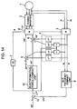
- Fig. 14 shows a configuration of its control system.
- Reference numeral 1 denotes an induction motor; 2 a power inverter for outputting an output voltage proportional to a voltage command value V1*; 3 a coordinate transformer for effecting the coordinate transformation of inverter output currents iu and iw and computing d-axis and q-axis currents id and iq; 4 a voltage computing unit for computing a value of a leak-impedance voltage drop of the motor on the basis of id, iq and an output frequency command value ⁇ 1*; 5 and 6 adders for adding the voltage drop value to induced-electromotive-force command values ed* and eq* and outputting d-axis and q-axis voltage command values Vd* and Vq*; 7 a phase reference generator for integrating ⁇ 1* and outputting a phase reference ⁇ ;
- JP-11018497 discloses a speed control method for an induction motor.
- the problem to be solved is to increase torque at the time of low speed.
- the q-axis current command value is brought to zero when the absolute value of a speed command value or a speed estimated value is lower than a set value. Further, a value is used which is obtained from a frequency estimated based on the difference between the speed command value and the speed estimated value. Both, d-axis current command id* and q-axis current command iq* are used for the control.
- JP-11187699 discloses a speed control method for an induction motor.
- the problem to be solved is to prevent torque shortage in a zero speed region by controlling a magnetic flux axis current to be at least the ordinary time value when a speed command value is at almost a specified value, replacing a frequency command value with a speed estimation value and performing operation on the basis of the speed command value.
- Both, d-axis current command id* and q-axis current command iq*, are used for control.
- the operating frequency ⁇ 1 of the motor 1 is controlled in proportion to ⁇ 1*, and the drop in the leak impedance is compensated by the action of the voltage computing unit 4.
- the induced electromotive force e of the motor 1 does not change irrespective of the magnitude of the torque.
- the magnetic flux of the motor is always kept constant, and a decline in the torque due to a decline in the magnetic flux of the motor is prevented.
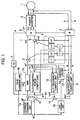
- Fig. 1 shows a block diagram of a vector controlling apparatus without a speed sensor for realizing the speed controlling method for an induction motor in accordance with an embodiment of the invention.
- Reference numerals 1 to 9, 12, and 13 denote constituent elements which are identical to those of the conventional example.
- Reference numeral 10 denotes a computing unit for determining a slip-frequency computed value ⁇ s2 on the basis of induced-electromotive-force command values ed* and eq*; 11, an adder for adding the aforementioned ⁇ s1 and ws2 and outputting a slip-frequency estimated value ⁇ s ⁇ ; 12, an adder for adding ⁇ s ⁇ to ⁇ r* and outputting ⁇ 1*; 14, a d-axis current commanding unit for outputting a d-axis-current command value id* which is greater than a normal value; 15, an amplifier for outputting a voltage command value ed* in accordance with a deviation between id* and id, a gain Gd being adapted to change in accordance with ⁇ r*; and 16, a gain commanding unit for commanding the gain Gd.
- Numeral 17 denotes a q-axis current limiter for controlling iq substantially to zero in a zero speed range, a gain Gq being adapted to change in accordance with ⁇ r*.
- Numeral 18 denotes a gain commanding unit for commanding the gain Gq.
- the operation of the constituent elements 1 to 9, 12, and 13 is the same as described above in the section on the related art.
- the present invention has as its object to prevent a decline in the torque due to variations of motor parameters in the conventional art, and the constituent elements designated at reference numerals 10, 11, and 14 to 18 constitute a characteristic configuration of the present invention.
- the constituent elements 14 to 16 are for controlling the d-axis current id to a predetermined value greater than a normal value in the zero speed range, and a deviation between the command value id* from the d-axis current commanding unit 14 and the detected value id from a coordinate transformer 3 is amplified by the amplifier 15, and ed* is outputted.
- Fig. 2 shows the relationship among the gain command Gd, the d-axis current id, and the speed command value ⁇ r*.
- eq* is corrected by the current limiter 17 to control iq substantially to zero.
- the input-output relation of the commanding unit 18 is shown in Fig. 3. Since the gain Gq assumes a large value in the zero speed range, eq* is corrected by an output value Gq ⁇ iq of the q-axis current limiter 17 in a direction for suppressing iq. Consequently, iq is controlled substantially to zero.
- FIG. 4 A vector diagram concerning the current and magnetic flux of the motor is shown in Fig. 4.
- ⁇ ⁇ is an angle formed by the magnetic flux ⁇ 2 and the current id
- M is exciting inductance
- ⁇ s1 and ⁇ s2 are added by the adder 11, and ⁇ s ⁇ shown in the following Formula (6) is outputted.
- ⁇ s ⁇ ⁇ 1 / T ⁇ 2 ⁇ iq / id + 1 / T ⁇ 2 ⁇ ed * / eq *
- Formula (6) agrees with Formula (5) since 1q ⁇ 0, and in the normal range Formula (6) agrees with Formula (1) since ed* ⁇ 0.
- eq* can be regarded as being proportional to ⁇ 1, so that the computation can be performed by using ⁇ 1* instead of eq* in Formula (6).
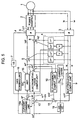
- Fig. 5 shows another embodiment of the present invention.
- the difference with the embodiment shown in Fig. 1 lies in that id* is decreased at ⁇ 1* ⁇ 0, and the relationship between ⁇ 1* and id* is shown in Fig. 6.
- ⁇ 1* 0, since the state of conduction does not shift between elements of the inverter, and a current is concentrated on particular elements, it is necessary to limit the inverter output current in comparison to a normal level.
- the content of the computation by a current commanding unit 14a is shown in Fig. 7.
- the computation shown in the following Formula (7) is performed by a function generator 141a, a delay circuit 142, and an adder 143, and id* having the relationship shown in Fig. 6 is outputted.
- the delay circuit 142 is for taking into consideration the transient withstand capacity (a delay in the temperature rise) of the elements with respect to the concentration of the current, and id0* is a reference value in a case where there is no concentration of the current.
- eq* can be regarded as being proportional to ⁇ 1, so that the computation can be performed by using ⁇ 1* instead of eq* in Formula (8).
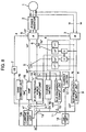
- Fig. 8 illustrates still another embodiment of the present invention.
- the difference with the embodiments shown in Figs. 1 and 5 lies in that id* is made variable in accordance with the torque in the zero speed range, and Fig. 9 shows the relationship between id* and the torque.
- id* is fixed irrespective of the relative magnitude of the torque
- id* becomes more than necessary during a light load, so that the motor loss (copper loss) increases by that margin. For this reason, it is preferable to decrease the inverter output current during a low torque.
- Fig. 10 The content of the arithmetic operation by a current commanding unit 14b in this embodiment is shown in Fig. 10.
- Reference numeral 19 denotes a computing unit (divider) which generates a ratio ed*/eq*.
- the computation shown in the following Formula (8) is performed by a function generator 141b and the adder 143 by using ed*/eq* from the computing unit 19, which is a value corresponding to the slip (torque) of the motor, and id* having the relationship shown in Fig. 9 is outputted.
- Fig. 11 illustrates a further embodiment of the present invention.
- id* is varied in accordance with ⁇ 1* and the torque in the zero speed range.
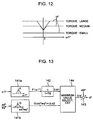
- Fig. 12 shows the relationship among id*, ⁇ 1*, and the torque.
- a current commanding unit 14c in this embodiment The content of the arithmetic operation by a current commanding unit 14c in this embodiment is shown in Fig. 13.
- the function generators 141a and 141b and the delay circuit 142 are similar to those of the above-described embodiments. Their outputs ⁇ id1 and ⁇ id2 are added to a maximum-value selecting circuit 144, and a greater one of these values is outputted as ⁇ id. Further, id* is computed in accordance with Formula (9). Consequently, id* changes in conformity with Fig. 12.
- ed*/eq* from the computing unit 19 i.e., the input signal of the function generator 141b
- eq* can be regarded as being proportional to ⁇ 1*, so that the computation can be performed by using ⁇ 1* instead of eq*.
Landscapes
- Engineering & Computer Science (AREA)
- Power Engineering (AREA)
- Control Of Ac Motors In General (AREA)
Claims (1)
- Un procédé de contrôle de la vitesse pour contrôler un moteur à induction raccordé à un inverseur de puissance en contrôlant une tension de sortie et une fréquence de sortie dudit inverseur (2) conformément à une commande de vitesse (ωr*) ou une commande de fréquence (ω1*),
dans lequel
la tension de sortie et la fréquence de sortie dudit inverseur de puissance sont contrôlées par un contrôleur (8) en utilisant une commande de tension d'axe d (Vd*) et une commande de tension d'axe q (Vq*) et une référence de phase (θ), si bien que ledit moteur génère un couple τ selon la formule:
dans laquelle k est un coefficient proportionnel, M est l'inductance d'excitation, id est un courant d'axe d, et θΦ est l'angle formé par un flux magnétique Φ2 et id, et
si une valeur absolue de la commande de vitesse (ωr*) ou la commande de fréquence (ω1*) est égale ou en dessous de la valeur paramétrée, en augmentant le courant d'axe d (id) à une valeur supérieure à une valeur normale, ladite valeur normale étant une valeur où la valeur absolue de la commande de vitesse (ωr*) ou de la commande de fréquence (ω1*) est égale ou supérieure à la valeur paramétrée, en corrigeant une valeur de commande de tension d'axe q (Vq*) conformément à une valeur détectée d'un courant d'axe q (Iq) et
en contrôlant l'axe de courant q (Iq) dans une direction dans laquelle le courant d'axe q devient zéro en changeant la valeur de commande de la tension d'axe q (VQ*),
caractérisé en ce que la valeur de commande de la tension d'axe q (Vq*) est constituée en soustrayant une valeur, obtenue en appliquant un gain (Gq) à l'axe de courant d'axe q détecté (Iq), à une valeur de commande de force électromagnétique induite par l'axe q (eq*), le gain étant sélectionné de manière à posséder une grande valeur si la valeur absolue de la commande de vitesse (ωt*) ou de la commande de fréquence (ω1*) est égale ou inférieure à la valeur paramétrée, et est 0 (zéro) si ladite valeur absolue est supérieure à la valeur paramétrée.
Applications Claiming Priority (2)
| Application Number | Priority Date | Filing Date | Title |
|---|---|---|---|
| JP2000052256A JP2001238499A (ja) | 2000-02-24 | 2000-02-24 | 誘導電動機の速度制御方法 |
| JP2000052256 | 2000-02-24 |
Publications (3)
| Publication Number | Publication Date |
|---|---|
| EP1128545A2 EP1128545A2 (fr) | 2001-08-29 |
| EP1128545A3 EP1128545A3 (fr) | 2002-04-24 |
| EP1128545B1 true EP1128545B1 (fr) | 2007-08-15 |
Family
ID=18573808
Family Applications (1)
| Application Number | Title | Priority Date | Filing Date |
|---|---|---|---|
| EP00118261A Expired - Lifetime EP1128545B1 (fr) | 2000-02-24 | 2000-09-04 | Procédé de contrôle d'un moteur à induction |
Country Status (4)
| Country | Link |
|---|---|
| US (1) | US6300741B1 (fr) |
| EP (1) | EP1128545B1 (fr) |
| JP (1) | JP2001238499A (fr) |
| DE (1) | DE60035949T2 (fr) |
Families Citing this family (14)
| Publication number | Priority date | Publication date | Assignee | Title |
|---|---|---|---|---|
| JP2002095298A (ja) * | 2000-09-14 | 2002-03-29 | Toshiba Corp | 電動機制御装置 |
| US6646412B2 (en) * | 2002-02-11 | 2003-11-11 | Ford Global Technologies, Llc | Method and system for controlling torque in a powertrain that includes an induction motor |
| JP4455075B2 (ja) * | 2004-01-28 | 2010-04-21 | 三菱電機株式会社 | モータ制御装置 |
| JP4760020B2 (ja) * | 2005-01-18 | 2011-08-31 | 三菱電機株式会社 | 誘導電動機の制御装置 |
| CN100377492C (zh) * | 2005-02-07 | 2008-03-26 | 天津大学 | 一种基于运动电动势控制的异步电动机调速方法 |
| JP4699923B2 (ja) * | 2006-03-13 | 2011-06-15 | 株式会社日立産機システム | 誘導電動機の駆動装置および方法 |
| EP1944862B1 (fr) * | 2007-01-15 | 2011-08-03 | Hitachi Industrial Equipment Systems Co., Ltd. | Contrôleur de moteur à induction |
| US7653102B2 (en) * | 2007-01-25 | 2010-01-26 | Avago Technologies Fiber Ip (Singapore) Pte. Ltd. | Method and apparatus for controlling output power levels of a laser used for optical data transmission based on data rate-speed optical feedback |
| CN103701393B (zh) * | 2013-12-27 | 2016-04-13 | 深圳市航盛电子股份有限公司 | 一种异步电机弱磁时转矩精度的补偿方法 |
| JP6431788B2 (ja) * | 2015-03-05 | 2018-11-28 | 株式会社日立産機システム | 電力変換装置およびその制御法 |
| JP6590457B2 (ja) * | 2015-07-27 | 2019-10-16 | 株式会社Soken | 車両駆動制御装置及び車両駆動制御方法 |
| JP6847191B2 (ja) * | 2019-12-23 | 2021-03-24 | 株式会社日立産機システム | 電力変換装置の制御方法および電力変換装置 |
| JP2022098727A (ja) * | 2020-12-22 | 2022-07-04 | 株式会社日立産機システム | 電力変換装置 |
| US11689131B2 (en) * | 2021-09-15 | 2023-06-27 | Deere & Company | System and method of a robust startup and stop scheme for position sensorless control of an electric machine |
Family Cites Families (17)
| Publication number | Priority date | Publication date | Assignee | Title |
|---|---|---|---|---|
| JPS58123394A (ja) * | 1982-01-18 | 1983-07-22 | Hitachi Ltd | 交流電動機の制御装置 |
| JPS61128790A (ja) * | 1984-11-26 | 1986-06-16 | Fuji Electric Co Ltd | 誘導電動機のすべり周波数演算装置 |
| JP3124019B2 (ja) * | 1990-05-16 | 2001-01-15 | 株式会社東芝 | 誘導電動機の制御装置 |
| JP3257566B2 (ja) * | 1992-06-16 | 2002-02-18 | 株式会社安川電機 | 誘導電動機のpgレスベクトル制御装置 |
| US5652495A (en) * | 1994-05-25 | 1997-07-29 | Matsushita Electric Industrial Co., Ltd. | Controller for permanent magnet synchronous motor |
| JP3240888B2 (ja) * | 1995-09-04 | 2001-12-25 | 株式会社日立製作所 | モータ制御装置、モータ制御方法、およびそれを用いた電気車 |
| JP3351244B2 (ja) * | 1996-07-05 | 2002-11-25 | 株式会社日立製作所 | 誘導電動機の速度制御方法 |
| US5959430A (en) * | 1997-03-07 | 1999-09-28 | Kabushiki Kaisha Toshiba | Power conversion system |
| JP3770286B2 (ja) * | 1997-05-14 | 2006-04-26 | 株式会社安川電機 | 誘導電動機のベクトル制御方法 |
| JP3772935B2 (ja) * | 1997-05-27 | 2006-05-10 | 株式会社安川電機 | 誘導電動機の制御装置 |
| DE19724946B4 (de) * | 1997-06-12 | 2005-09-15 | Siemens Ag | Verfahren und Vorrichtung zur Drehzahlregelung einer geberlosen, feldorientiert betriebenen Asynchronmaschine |
| JP3602938B2 (ja) * | 1997-06-20 | 2004-12-15 | 株式会社日立製作所 | 誘導電動機の速度制御方法 |
| JPH11187700A (ja) * | 1997-12-24 | 1999-07-09 | Fuji Electric Co Ltd | 誘導電動機の制御装置 |
| JPH11187699A (ja) * | 1997-12-24 | 1999-07-09 | Hitachi Ltd | 誘導電動機の速度制御方法 |
| US6014007A (en) * | 1998-09-29 | 2000-01-11 | Allen-Bradley Company Llc | Method and apparatus for starting an AC drive into a rotating motor |
| JP2000116199A (ja) * | 1998-10-01 | 2000-04-21 | Toshiba Corp | 電動機制御装置 |
| JP3815113B2 (ja) * | 1999-04-23 | 2006-08-30 | 株式会社日立製作所 | 誘導電動機の制御方法 |
-
2000
- 2000-02-24 JP JP2000052256A patent/JP2001238499A/ja active Pending
- 2000-09-01 US US09/654,088 patent/US6300741B1/en not_active Expired - Fee Related
- 2000-09-04 EP EP00118261A patent/EP1128545B1/fr not_active Expired - Lifetime
- 2000-09-04 DE DE60035949T patent/DE60035949T2/de not_active Expired - Fee Related
Non-Patent Citations (1)
| Title |
|---|
| None * |
Also Published As
| Publication number | Publication date |
|---|---|
| EP1128545A2 (fr) | 2001-08-29 |
| DE60035949D1 (de) | 2007-09-27 |
| JP2001238499A (ja) | 2001-08-31 |
| DE60035949T2 (de) | 2007-12-06 |
| US6300741B1 (en) | 2001-10-09 |
| EP1128545A3 (fr) | 2002-04-24 |
Similar Documents
| Publication | Publication Date | Title |
|---|---|---|
| EP1128545B1 (fr) | Procédé de contrôle d'un moteur à induction | |
| US6628099B2 (en) | Synchronous motor driving system and sensorless control method for a synchronous motor | |
| US6642689B2 (en) | Control apparatus for power converter | |
| US6344726B1 (en) | Method of controlling an induction motor | |
| US9991829B2 (en) | Direct-axis current protection method and device for permanent magnet synchronous motor drive system | |
| KR0138730B1 (ko) | 유도 모터용 벡터 제어 시스템 | |
| US6611124B2 (en) | Control apparatus of induction motor | |
| JPH11187699A (ja) | 誘導電動機の速度制御方法 | |
| KR100563225B1 (ko) | 유도전동기의제어장치 | |
| JP2003088194A (ja) | 電動機駆動システム | |
| JP3067659B2 (ja) | 誘導電動機の制御方法 | |
| JP3351244B2 (ja) | 誘導電動機の速度制御方法 | |
| JP7433445B2 (ja) | モータ鉄損演算装置およびそれを備えたモータ制御装置 | |
| JP7243537B2 (ja) | 誘導電動機の制御装置 | |
| JP3736551B2 (ja) | 誘導電動機の速度制御方法 | |
| JP3602938B2 (ja) | 誘導電動機の速度制御方法 | |
| JP3161904B2 (ja) | 誘導電動機のベクトル制御方法及びその装置 | |
| JP3716347B2 (ja) | 誘導電動機駆動装置、誘導電動機制御装置及び誘導電動機制御方法 | |
| JP3446557B2 (ja) | 誘導電動機の速度制御方法 | |
| JP2738721B2 (ja) | 誘導電動機の速度制御装置 | |
| JP3770228B2 (ja) | 誘導電動機の速度制御方法 | |
| JP3891103B2 (ja) | 誘導電動機の速度制御方法 | |
| JPS61106091A (ja) | 誘導電動機のすべり周波数演算装置およびその装置を用いた誘導電動機の回転数制御装置 | |
| JPH0965700A (ja) | 誘導電動機制御装置 | |
| JP3066697B2 (ja) | 誘導電動機のベクトル制御方法及び装置 |
Legal Events
| Date | Code | Title | Description |
|---|---|---|---|
| PUAI | Public reference made under article 153(3) epc to a published international application that has entered the european phase |
Free format text: ORIGINAL CODE: 0009012 |
|
| AK | Designated contracting states |
Kind code of ref document: A2 Designated state(s): AT BE CH CY DE DK ES FI FR GB GR IE IT LI LU MC NL PT SE Kind code of ref document: A2 Designated state(s): DE FR GB |
|
| AX | Request for extension of the european patent |
Free format text: AL;LT;LV;MK;RO;SI |
|
| PUAL | Search report despatched |
Free format text: ORIGINAL CODE: 0009013 |
|
| AK | Designated contracting states |
Kind code of ref document: A3 Designated state(s): AT BE CH CY DE DK ES FI FR GB GR IE IT LI LU MC NL PT SE |
|
| AX | Request for extension of the european patent |
Free format text: AL;LT;LV;MK;RO;SI |
|
| 17P | Request for examination filed |
Effective date: 20020823 |
|
| AKX | Designation fees paid |
Free format text: DE FR GB |
|
| 17Q | First examination report despatched |
Effective date: 20030623 |
|
| GRAP | Despatch of communication of intention to grant a patent |
Free format text: ORIGINAL CODE: EPIDOSNIGR1 |
|
| GRAS | Grant fee paid |
Free format text: ORIGINAL CODE: EPIDOSNIGR3 |
|
| RAP1 | Party data changed (applicant data changed or rights of an application transferred) |
Owner name: HITACHI, LTD. |
|
| GRAA | (expected) grant |
Free format text: ORIGINAL CODE: 0009210 |
|
| AK | Designated contracting states |
Kind code of ref document: B1 Designated state(s): DE FR GB |
|
| REG | Reference to a national code |
Ref country code: GB Ref legal event code: FG4D |
|
| REF | Corresponds to: |
Ref document number: 60035949 Country of ref document: DE Date of ref document: 20070927 Kind code of ref document: P |
|
| ET | Fr: translation filed | ||
| PLBE | No opposition filed within time limit |
Free format text: ORIGINAL CODE: 0009261 |
|
| STAA | Information on the status of an ep patent application or granted ep patent |
Free format text: STATUS: NO OPPOSITION FILED WITHIN TIME LIMIT |
|
| 26N | No opposition filed |
Effective date: 20080516 |
|
| PGFP | Annual fee paid to national office [announced via postgrant information from national office to epo] |
Ref country code: FR Payment date: 20080814 Year of fee payment: 9 |
|
| PGFP | Annual fee paid to national office [announced via postgrant information from national office to epo] |
Ref country code: GB Payment date: 20080820 Year of fee payment: 9 |
|
| PGFP | Annual fee paid to national office [announced via postgrant information from national office to epo] |
Ref country code: DE Payment date: 20080908 Year of fee payment: 9 |
|
| GBPC | Gb: european patent ceased through non-payment of renewal fee |
Effective date: 20090904 |
|
| REG | Reference to a national code |
Ref country code: FR Ref legal event code: ST Effective date: 20100531 |
|
| PG25 | Lapsed in a contracting state [announced via postgrant information from national office to epo] |
Ref country code: FR Free format text: LAPSE BECAUSE OF NON-PAYMENT OF DUE FEES Effective date: 20090930 Ref country code: DE Free format text: LAPSE BECAUSE OF NON-PAYMENT OF DUE FEES Effective date: 20100401 |
|
| PG25 | Lapsed in a contracting state [announced via postgrant information from national office to epo] |
Ref country code: GB Free format text: LAPSE BECAUSE OF NON-PAYMENT OF DUE FEES Effective date: 20090904 |