EP1128601B1 - Système de transmission, dispositif de supervison, procedé pour sortir des données dans le dispositif et des noeuds pour transmettre dans le système - Google Patents
Système de transmission, dispositif de supervison, procedé pour sortir des données dans le dispositif et des noeuds pour transmettre dans le système Download PDFInfo
- Publication number
- EP1128601B1 EP1128601B1 EP01301487A EP01301487A EP1128601B1 EP 1128601 B1 EP1128601 B1 EP 1128601B1 EP 01301487 A EP01301487 A EP 01301487A EP 01301487 A EP01301487 A EP 01301487A EP 1128601 B1 EP1128601 B1 EP 1128601B1
- Authority
- EP
- European Patent Office
- Prior art keywords
- performance data
- data
- supervisory control
- created
- section
- Prior art date
- Legal status (The legal status is an assumption and is not a legal conclusion. Google has not performed a legal analysis and makes no representation as to the accuracy of the status listed.)
- Expired - Lifetime
Links
Images










Classifications
-
- H—ELECTRICITY
- H04—ELECTRIC COMMUNICATION TECHNIQUE
- H04L—TRANSMISSION OF DIGITAL INFORMATION, e.g. TELEGRAPHIC COMMUNICATION
- H04L43/00—Arrangements for monitoring or testing data switching networks
- H04L43/02—Capturing of monitoring data
- H04L43/026—Capturing of monitoring data using flow identification
Definitions
- a transmission system comprises nodes for transmitting communication data and supervisory control devices for maintaining and operating a communication network.
- the supervisory control devices maintain or operate the communication network on the basis of the management information received from the individual nodes.
- the management object definition, network management procedure, and others have been recommended in ISO (International Organization for Standardization) or ITU (International Telecommunication Union).
- One piece of management information is performance data created at each node.
- Each node periodically monitors the value of data representing the time during which errors exceeded the allowed value for each monitoring item, such as the bit error rate of transmission data, or the number of errors occurred, and creates performance data on the basis of the result of the monitoring.
- Kiriha Y et al "Fault Analysis Expert System for Unified Network Management: Exnets" NEC Research and Development, JP, Nippon Electric Ltd. Tokyo, vol. 33, no. 1, 1992, pages 117-125 and
- the zero suppression function is the function of reducing the amount of the performance data created. Use of this function makes it possible to reduce the burden of creating performance data on the nodes, the burden of processing the performance data on the supervisory control devices, and the communication burden of informing the performance data on the network.
- data about each monitoring item is monitored at specific intervals of time, for example, at intervals of 15 minutes.
- performance data is created. It is assumed that in a monitoring period, data items about all the monitoring items take a value of 0. In this case, at a node with the zero suppression function, no performance data will be created in that monitoring period. Instead, the number of times performance data was not created is counted up.
- the zero suppression function produces no performance data in that period for up to 8 hours (that is, equivalent to consecutive 32 times of monitoring).
- Such a process suppresses the number of pieces of performance data, reducing the number of times a node informs the supervisory control device of performance data, which alleviates the burden particularly on the network.
- An first object of the present invention is to provide a transmission system which has a zero suppression function and is capable of offering information the user needs as much as possible to achieve an improved human-machine interface (HMI), a supervisory control device, and a method of outputting the data in the supervisory control device.
- HMI human-machine interface
- a second object of the present invention is to provide a node which alleviates the burden of communication related to notice of performance data.
- a transmission system comprising a plurality of nodes forming a network and a supervisory control device for managing the network on the basis of performance data created at these nodes, wherein each of the plurality of nodes includes performance data generating means for measuring individual data items about the monitoring items defined for a plurality of objects to be measured according to a specific schedule and, on the basis of the result of the measurement, creating the performance data using a zero suppression function of suppressing a succession of zero data items, and performance data sending means for sending the performance data created at the performance data generating means to the supervisory control device, and the supervisory control device includes reception means for receiving the performance data send from the nodes, storage means for accumulating a history of the received performance data, user interface means for accepting the user's data output request with specified retrieval conditions including a time range and outputting the data fulfilling the request, and output control means which determines the cause that the performance data is absent, when the performance data that should be present in the storage means according to the schedule is absent in the time range specified
- the cause is determined. If the cause that there is a piece of performance data that could not be acquired is the execution of zero suppression at the performance data generating means, the data item related to the performance data that could not be acquired will be made zero and then output data be created. The output data will be outputted in the form of screen display or printout.
- the supervisory control device inserts 0s in the data related to the absent performance data.
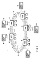
- FIG. 1 shows the configuration of a transmission system related to a first embodiment of the present invention.
- the system is provided with an n number of nodes N1 to Nn connected in a ring via a line cable OF.
- the line cable OF has a transmission capacity of STM-64 (Synchronous Transfer Module-Level 64) class in the SDH standard.
- the line cable OF includes a live transmission path SL and a backup transmission path PL.
- Each of the transmission paths SL, PL includes clockwise (CW) and counterclockwise (CCW) circuits.
- Nodes N1 to Nn drop specific slots from the time slots time-division multiplexed onto the STM-64 signal transmitted via the line cable OF.
- the dropped slots are sent as a low-order group signal to low-order group devices (not indicated by reference numerals) on the tributary side, including an exchange and an end office.
- nodes N1 to Nn multiplex the low-order group signals, including STM-1, STM-4, STM-16, and STM-64, sent via the tributary transmission path LL from the low-order group devices onto specific time slots of a STM-64 signal.
- the multiplexed signal is sent to another node. In this way, a transmission path with a specific transmission capacity is set between nodes N1 to Nn.
- the system of FIG. 1 is further provided with a plurality of supervisory control devices M1 to Mn.
- Supervisory control devices M1 to Mn are connected to nodes N1 to Nn via a LAN (Local Area Network).
- Supervisory control devices M1 to Mn receive information from nodes N1 to Nn respectively, and on the basis of the information, set a communication path in the network or monitor an alarm.
- Such functions of supervisory control devices M1 to Mn are realized by installing dedicated application programs on, for example, a general-purpose workstation.
- the notice information sent from the nodes N1 to Nn is particularly transmitted to the supervisory control devices M1 to Mn via a LAN.
- a LAN forms a communication network for managing the network, namely a management network. Traffic for transmitting the notice information to the supervisory control devices M1 to Mn mainly takes the route of a LAN. For this reason, it is necessary to prevent a LAN from becoming a bottleneck in exchanging the notice information.
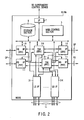
- FIG. 2 shows the configuration of nodes N1 to Nn related to the first embodiment of the present invention.
- reference numerals 1-0 indicates a live line interface section (HS I/F) to which the live transmission path SL is connected.
- Reference numeral 1-1 indicates a standby line interface section to which the standby transmission path PL is connected.
- TSA time slot assignment section
- TSA 2-0 and TSA 2-1 drop specific time slots from the time slots time-division multiplexed onto the STM-64 signal.
- the dropped slots are set as a low-order signal from the tributary transmission path LL via tributary interface (LS I/F) shelves 3-1 to 3-k.
- LS I/F tributary interface
- the low-order group signal introduced into the device via the tributary transmission path LL from the tributary transmission path LL via LS I/F shelves 3-1 to 3-k are supplied to TSA 2-0 and TSA 2-1, which add the signal to specific time slots of the STM-64 frame.
- the resulting signal is sent to another node via the line cable OF.
- TSA 2-0 is used as a live unit in a normal operation of the system. If a failure occurs in TSA 2-0, TSA 2-1 will be operated in place of TSA 2-0. In this way, redundancy in the device is realized.
- Each of nodes N1 to Nn in FIG. 2 further includes a main control section 5, a storage section 6 that stores various kinds of control programs, and a management network interface (I/F) 7 that interfaces with supervisory control devices M1 to Mn.
- a management network interface I/F
- FIG. 3 shows the configuration of each of supervisory control devices M1 to Mn.
- Supervisory control devices M1 to Mn execute the management of the entire system on the basis of the performance data received from nodes N1 to Nn.
- Each of supervisory control devices M1 to Mn includes an operator's section 21, a display section 25, an input/output section 80 with a printout section 26, an interface (I/F) section 90 that provides connection interface with the individual nodes N1 to Nn via the LAN, a storage section 100 that stores various kinds of supervisory control programs, and a control section 110.
- I/F interface
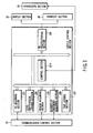
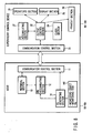
- FIG. 4 is a functional block diagram showing the configuration of each of nodes N1 to Nn and each of supervisory control devices M1 to Mn in a first embodiment of the present invention.
- the basic configuration of nodes N1 to Nn is shown in FIG. 2.
- the main control section 5 of FIG. 2 comprises a communication control section 11 for information communication with supervisory control devices M1 to Mn, a performance data accumulating section (hereinafter, referred to as a PD accumulating section) 12, a retrieval section 13, and a performance data generating section (hereinafter, referred to as a PD generating section) 14.
- the PD accumulating section 12 stores performance data created at the PD generating section 14. That is, a history of the performance data is accumulated in the PD accumulating section 12.
- the retrieval section 13 retrieves the performance data corresponding to the request from supervisory control devices M1 to Mn from the PD accumulating section 12.
- the communication control section 11 controls communication for transmitting and receiving the performance data and other information to and from supervisory control devices M1 to Mn. Specifically, the communication control section 11 transmits and receives the information to and from supervisory control devices M1 to Mn via the I/F 7 of FIG. 2.
- the PD generating section 14 measures, at specific intervals of time, data items about the individual monitoring items defined for a plurality of objects to be measured in the HS I/F and LS I/F of its own node and generates pieces of performance data on the basis of the results of the measurement.
- the PD generating section 14 effects zero suppression and generates no performance data.
- a specific period of time for example, eight hours
- the PD generating section 14 cancels the zero suppression temporarily and then creates performance data. Thereafter, it waits for the value of the data to change.
- the PD generating section 14 includes a management table MT as shown in the figure.
- monitoring objects In the management table, monitoring objects, monitoring items, the number Ns of times zero suppression was effected, and others are stored.
- Monitoring objects are information as to, for example, which section of which channel is to be monitored.
- Performance events are information representing such items as TCCV or ES explained later.
- the PD generating section 14 creates performance data on the basis of the contents stored in the management table MT.
- the monitoring items include TCCV (Total Count of Code Violation), BBE (Background Block Error), ES (Erroneous Second), SES (Seriously Erroneous Seconds), UAS (Unavailable Seconds), OFS (Out-of-Frame Second), PJC (Pointer'Justification Count), PSC (Protection Switch Count), and PSD (Protection Switch Duration).
- TCCV Total Count of Code Violation
- BBE Background Block Error
- ES Erroneous Second
- SES Ses Erroneous Seconds
- UAS Unavailable Seconds
- OFS Out-of-Frame Second
- PJC Pointer'Justification Count
- PSC Protection Switch Count
- PSD Protection Switch Duration
- each of supervisory control devices M1 to Mn comprises not only the operator's section 21, display section 25, and printout section 26 but also an output control section 22, a communication control section 23, and a clock section 24.
- the communication section 23 controls information communication between its own device and nodes N1 to Nn.
- the clock section 24 generates an operating clock in its own device.
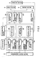
- FIG. 5 is a functional block diagram of the output control section 22 of FIG. 4.
- the output control section 22 in the first embodiment comprises a PD acquiring section 221, a time judging section 222, a period acquiring section 223, a zero suppression judging section 225, a PD restructuring section 226, a number-of-omissions acquiring section 229, and a control section 2211.
- the PD acquiring section 221 accepts this operation. Then, the PD acquiring section 221 acquires the performance data according to the retrieval conditions specified by the operation (that is, the retrieval conditions including the time range of the desired data, the required node, and the type of event). In the operation, the PD acquiring section 221 further acquires time TC that the latest performance data was created from the node from which the performance data was read.
- the retrieval conditions specified by the operation that is, the retrieval conditions including the time range of the desired data, the required node, and the type of event.
- the PD acquiring section 221 further acquires time TC that the latest performance data was created from the node from which the performance data was read.
- the period acquiring section 223 acquires a totalizing period T1 of performance data at the node from which performance data is read.
- the time judging section 222 compares the time range the operator requested with Tc and T1 and judges whether the time that performance data is to be created is present after the time range the operator requested.
- the time that performance data is to be created means the time that performance data is necessarily created in the totalizing period T1 of performance data after time Tc, that is, Tc + T1.
- the number-of-omissions acquiring section 229 acquires the number Ns of times the creation of performance data was omitted from the node being operated.
- the zero suppression judging section 225 judges whether zero suppression is effected at the node being operated.
- the PD restructuring section 226 inserts 0s into the indefinite area of the performance data acquired from the node being operated and uses the resulting information for screen display or printout.
- the indefinite area represents the area where no performance data is stored in the PD accumulating section 27 in the time range the operator requested.
- the control section 2211 supervises various control operations in the PD acquiring section 221, time judging section 222, period acquiring section 223, zero suppression judging section 225, PD restructuring section 226, and number-of-omissions acquiring section 229.
- the PD acquiring section 221, time judging section 222, period acquiring section 223, zero suppression judging section 225, PD restructuring section 226, number-of-omissions acquiring section 229, and control section 2211 are functions realized by putting a new patch on a conventional program written in, for example, a dedicated language. That is, these functional objects are based on a concept including both hardware and software.
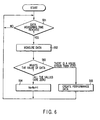
- zero suppression is effected at the PD generating section 14 at each of nodes N1 to Nn.
- step S61 When the measuring time of data is reached at step S61 in FIG. 6, data about each of the monitoring items is measured at step S62. At the next step S63, it is judged whether or not the value of the measured data includes a 0.
- step S64 the number of times the creation of performance data was skipped, or the number Ns of times the creation of performance data was omitted, is counted up.
- step S63 if there is a monitoring item whose data takes a value other than 0, control will go to step S65, where performance data will be created.
- supervisory control device M1 waits for an operation.
- the operator has carried out operations to request the output of data about node N1. That is, it is assumed that the operator has carried out operations to request the display of data about node N1 on the display section 25, the printing out of the display data from the printout section 26, or both of these.
- the retrieval conditions including the time range of the desired data, the identification code of the requested node (here, the one corresponding to node N1), and the type of monitoring item (for example, ES (Erroneous Second)) are set.
- the time the capital letter T closer to the present time in the time range from time t to time T is important.
- time T is referred to as the latest request time T.
- the latest request time is often set as the present time and the data is specified in such a manner that it belongs to the time range of a specific number of hours before the present time T.
- supervisory control device M1 accesses node N1 and acquires time Tc that the latest one was created in the pieces of performance data stored in the PD accumulating section 12 (step S2). Next, supervisory control device M1 compares the acquired Tc with the latest request time T (step S3). At this step, if T ⁇ Tc (N), supervisory control device M1 will read the performance data in the desired time rage from the PD accumulating section 12 (step S4) and output the performance data in the form of screen display or printout (step S12 in FIG. 7B).
- supervisory control device M1 accesses the PD generating section 14 of node N1 and acquires the totalizing period T1 of data (step S5). Then, supervisory control device M1 starts the process of determining the cause of creating no performance data after Tc.
- supervisory control device M1 judges in the totalizing period T1 whether a time that performance data is to be created is present in the time range from Tc to the latest request time T (step S6). Whether or not a time that performance data is to be created is present can be judged by deciding whether the expression T - Tc > T1 holds. That is, if T - Tc > T1 holds (Y: in the case of true), a longer time than the performance data creating period T1 has elapsed from when the performance data was created last until now. Therefore, since a time that performance data is to be created should be present, the processing of supervisory control device M1 moves to step S7 (see FIG. 7B). At this time, because performance data is considered not to have been created for some reason, its cause is inspected.
- step S6 if T - Tc > T1 does not hold (N: in the case of false), there is no time that performance data is to be created. Thus, there is no problem, when the performance data read from the PD accumulating section 27 is outputted as it is. Therefore, supervisory control device M1 goes to step S4, reads the performance data in the range of the operator's request, and then outputs the performance data in the form of screen display or printout (step S12 in FIG. 7B).
- step S6 the performance data corresponding to that time is not in the PD accumulating section 12, although performance data is to be created after the time range the operator requested. If its cause were not determined, the outputted data would be indefinite.
- supervisory control device M1 accesses the PD generating section 14 of node N1 and acquires the number Ns of times the creation of data was omitted (step S7). Then, supervisory control device M1 judges whether the absence of performance data is attributable to zero suppression effected at nose N1 or to any failure (step S8).
- supervisory control device M1 will go to step S10, where it will read performance data, make the data related to the performance data that could not be read 0 (step S11), and restructure the data to be outputted. Finally, supervisory control device M1 outputs the restructured data in the form of screen display or printout (step S12).
- supervisory control devices M1 to Mn in the first embodiment acquire the latest performance data creating time Tc from the called node, when the operator carries out an operation to request the output of data. Then, when supervisory control devices M1 to Mn cannot acquire all the performance data items in the time range requested, they acquire the totalizing period T1 of performance data from the node. Then, supervisory control devices M1 to Mn check whether a time that performance data is to be created is present after time T. If the time is present, supervisory control devices M1 to Mn acquire the number Ns of times the creation of performance data was omitted at the node and check whether zero suppression has been effected at the node. If zero suppression has been effected, supervisory control devices insert 0s into the data they could not be acquired and thereafter output the resulting data.
- the transmission system with the zero suppression function can offer as much information the user needs as possible and improve the human-machine interface (HMI).
- HMI human-machine interface
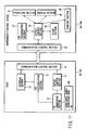
- FIG. 8 is a functional block diagram showing the configuration of each of nodes N1 to Nn and each of supervisory control devices M1 to Mn in the second embodiment.
- the configuration of FIG. 8 differs from that of FIG. 4 in that each of supervisory control devices M1 to Mn has a PD accumulating section 27.
- FIG. 9 is a functional block diagram of the output control section 22 of FIG. 8.
- the output control section 22 of the second embodiment further includes a PD retrieval section 224, a lacked data read section 227, a PD write section 228, and a time management section 2210.
- the PD acquiring section 221B of FIG. 9 differs from the PD acquiring section 221 of FIG. 5 in its function. For this reason, the PD acquiring section in FIG. 9 is indicated by a different reference numeral of 221B.
- the PD acquiring section 221B acquires the performance data from the individual nodes N1 to Nn at, for example, regular intervals according to a specific schedule.
- the PD acquiring section 221B differs from the PD acquiring section 221 of the first embodiment in that it positively acquires the performance data.
- the PD retrieval section 224 retrieves the performance data satisfying the retrieval conditions specified by the operator from the PD accumulating section 27 of its own device.
- the PD write section 228 stores the performance data acquired at the PD acquiring section 221B into the PD accumulating section 27.
- the lacked data read section 227 regards the data as being lacked and acquires the lacked data from the node being operated.
- the time management section 2210 stores time Tc that the latest performance data stored in the PD accumulating section 27 was created, while updating the creation time Tc. Particularly when the creation time has not been written in the reported performance data, the time management section regards the time it receives the performance data as the creation time of the performance data.
- supervisory control device M1 waists for arrival of performance data reading time or operation by the operator.
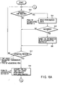
- supervisory control device M1 When the reading time has been reached at step S13 (Y), supervisory control device M1 reads the performance data from the PD accumulating section 12 of the node (step S14). When the reading process is successful (Y in step S15), supervisory control device M1 writes the read-out performance data into the PD accumulating section 27 (step S16). At that time, the time management section 2210 updates the latest performance data creating time Tc.
- supervisory control device M1 When an operation is carried out at step S17, supervisory control device M1 performs operations according to the procedure in step S18 to step S23 (see FIG. 10B). Since the procedure is the same as that in step S2 to step S8, its explanation will be omitted.
- the procedure in the second embodiment differs from that in the first embodiment in that the section from which time Tc is acquired in step S18 of FIG. 10A is the PD accumulating section 27.
- supervisory control device M1 will read the performance data, inserts 0s into the data related to the performance data that could not be read, and then output the resulting information (step S24, step S25, and step S31).
- supervisory control device M1 will proceed to step S26, where it will read the lacked data. That is, when (N) at step S23, there is a discrepancy between the number Ns of times the creation of performance data was omitted and time Tc. That is, the data to be stored is not in the PD accumulating section 27. Then, supervisory control device M1 accesses the PD accumulating section 12 of the node, reads the data, and supplements what is stored in the PD accumulating section 12 of its own device.
- supervisory control device M1 If failing to read the lacked data (N at step S27), supervisory control device M1 will read the performance data directly from the PD accumulating section 27 and output it (step S30 and step S31). In this case, the data related to the performance data that could not be acquired is outputted in the form of blank spaces.
- supervisory control device M1 If the lacked data has been read successfully (Y at step S27), supervisory control device M1 will add the read-out data to the contents of the PD accumulating section 27 (step S28). Then, after supervisory control device M1 updates the latest performance data creating time Tc (step S29), it goes to step S30.
- the second embodiment makes it possible to grasp the situation where the performance data has not reached the supervisory control device, although it has been created. Furthermore, in the second embodiment, when such a situation has occurred, the performance data that did not reached the supervisory control device is read from the database of the node and written into the PD accumulating section 27 of supervisory control devices M1 to Mn. This not only produces the effect explained in the first embodiment but also prevents the data to be recorded in the database on the side of supervisory control devices M1 to Mn from being omitted.
- the third embodiment is the same as the second embodiment in each of supervisory control devices M1 to Mn is provided with a database.
- the system of the third embodiment differs from that of the second embodiment in a method of reporting the performance data.
- the configuration of nodes N1 to Nn in the third embodiment differs from that in the second embodiment. That is, as shown in FIG. 11, each of nodes N1 to Nn includes a notice control section 15.
- the notice control section 15 automatically notifies the performance data created at the PD generating section 14 to the supervisory control devices without waiting for the request of the supervisory control devices.
- FIG. 12 shows the configuration of the output control section 22 of each of supervisory control devices M1 to Mn related to the third embodiment.
- the PD accumulating section 221B of FIG. 9 is omitted. The reason is that the performance data is reported unilaterally from the node side.
- supervisory control device M1 waits for notice of performance data from nodes N1 to Nn (step S32). When having received performance data, supervisory control device M1 writes the received performance data in the PD accumulating section 27 of its own device (step S33). Next, supervisory control device M1 waits for an operation by the operator (step S34). When there is no operation (N), the loop of step S32 to step S34 is continued.
- supervisory control device M1 proceeds to step S35, where it acquires the latest performance data creating time Tc. Then, supervisory control device M1 goes to step S19 of FIG. 10B, where it follows the same procedure as that in the second embodiment.
- the third embodiment produces the same effects as those of the first and second embodiments, except that the way supervisory control devices M1 to Mn acquire the performance data differs.
- FIG. 14 shows the configuration of each of nodes N1 to Nn and each of supervisory control devices M1 to Mn related to the fourth embodiment.
- FIG. 14 the same parts as those in FIGS. 4, 8, and 11 are indicated by the same reference numerals and only the different parts will be explained.
- the configuration of supervisory control devices M1 to Mn is the same as that in FIG. 4 and therefore only nodes N1 to Nn will be described.
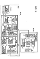
- each of nodes N1 to Nn includes main-signal circuit boards C1 to Ct, a sub-circuit board SC, and a main circuit board MC.
- the main-signal circuit boards C1 to Ct, sub-circuit board SC, and main circuit board MC are installed in the form of cards that can be inserted and removed into and from a general-purpose shelf (not shown).
- the main-signal circuit boards C1 to Ct correspond to the live high-speed interface section (HS I/F) 1-0, the standby high-speed interface sections 1-1, TSA2-0, 2-1, and low-speed interface sections (LS I/F) 3-1 to 3-k in FIG. 2.
- the main circuit board MC corresponds to the main control section 5 of FIG. 2.
- the sub-circuit board SC corresponds to the sub-control board provided in either the HS I/F or LS I/F of FIG. 2.
- the sub-circuit board SC may be provided in the main circuit board 5.
- the sub-circuit board SC includes a performance data computing section (hereinafter, referred to as a PD computing section) 16, a performance data storage section (hereinafter, referred to as a storage section) 17, a channel information storage section 18, a PD message creating section 19, a channel information acquiring section 110, and an interboard communication control section 111S.
- the PD computing section 16 monitors the state of the main-signal circuit boards C1 to Ct and totalizes the data items related to the high-speed circuits OF and low-speed circuits LL at intervals of 15 minutes every day. From the totalized data, the PD computing section calculates performance data. The calculated performance data is stored in the PD storage section 17.
- FIG. 15 illustrates how the performance data is stored in the PD storage section 17.
- the performance data is stored for each of the channels (Ch1, Ch2, ...) in such a manner that it is caused to correspond to a plurality of management sections (RS (Remote Section), MS (Multiplex Section), and PS (Path Section)).
- RS Remote Section
- MS Multiplex Section
- PS Path Section
- the channel information acquiring section 110 receives information about whether the low-speed I/Fs have been installed in shelves 3-1 to 30k and about the type of boards from the main-signal circuit boards C1-to Ct. Then, on the basis of the received information, the channel information acquiring section 110 acquires the configuration information about the circuit boards. The configuration information is written in the channel information storage section 18.
- the main-signal circuit boards C1 to Ct include plural types of circuit boards: they are STM-1, STM-4, STM-16, and STM-64.
- the plural types of circuit boards are dealt with by writing information indicating the type of board into Bit 0 to Bit 3 set in the storage area of the channel information storage section 18.
- the information indicating the type of circuit board is acquired by the channel information acquiring section 110.
- the channel information acquiring section 110 receives create information (or information about a new channel or the creation of a new path) about the APS (Automatic Protection Switching) function many SDH units have from an APS function object in the form of messages.
- the received APS create information is written into Bit 5 of the channel information storage section 18.
- the PD message creating section 19 reads each piece of performance data stored in the PD storage section 17. Referring to the read-in information and the mounting state of the circuit board of each channel acquired from the channel information storage section 18, the PD message creating section 19 creates a performance data message. The created performance data message is transferred to a compressing section 113 in the main circuit board MC via the interboard communication control sections 111S, 111M.
- the compression information in the channel information storage section 18 is set to 0 (that is, no compressing is done)
- the data will not be compressed at the sub-circuit board SC.
- the performance data message about all the channels mounted in the shelves will be transferred directly to the compressing section 113.
- the compression information is set to F (that is, compressing is done)
- the data will be compressed at the sub-circuit board SC.
- the performance data about all the channels mounted in the shelves will be compressed, thereby creating a performance data message.
- the performance data message will be transferred to the compressing section 113.
- the interboard communication control section 111S performs data communication with the main circuit board MC.
- the main circuit board MC includes not only the communication control section 11 communicating with supervisory control devices M1 to Mn but also an interboard communication control section 111M, a contact information acquiring section 112, the compressing section 113, and the configuration information storage section 114.
- the interboard communication control section 111M performs data communication with the sub-circuit board SC.
- the contact information acquiring section 112 reads the contact information and writes it into the configuration information storage section 114.
- the contact information is information indicating the state of the low-speed I/Fs 3-1 to 3-k mounted in the shelves.
- the contact information is set beforehand in the nodes by using dip switches (Dip Sw) or the like. Since there are several types of circuit boards in the shelves at the same time, 4 bits (Bit 0 to Bit 3) are given to each shelf as shown in FIG. 17, thereby distinguishing the types of circuit boards.
- Information on each shelf including the compression information and contact information, is transferred to the channel information acquiring section 110 via the interboard communication sections 111M, 111S, when the node is started up.
- the compressing section 113 changes the compression unit of performance data on the basis of the configuration information acquired from the channel information acquiring section 110 and compresses the performance data message received from the PD message creating section 19 according to the changed unit.
- the compression unit of performance data varies according to the configuration information about the node.
- the compressing section 113 receives the performance data message from the PD message creating section 19, the compressing section 113 checks the compression information in the corresponding shelf in the configuration information storage section 114. If the result of the check has shown that the compression information has a value of 1, meaning that the received performance data has been compressed, the compressing section 113 will transmit the performance data message to the output control section 22 of supervisory control device M1. If the result of the check has shown that the compression information has a value of 0, the compressing section 113 compresses the performance data about all the shelves, thereby creating a performance data message. Then, the compressing section 113 transmits the created performance data message to the output control section 22 of supervisory control device M1.
- the output control section 22 of each of supervisory control devices M1 to Mn is provided with the function of storing the performance data in a decompressed state in the PD accumulating section 27, when the section 22 has received the compressed performance data.
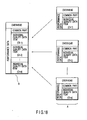
- FIG. 18 shows the structure of the performance data reported to supervisory control devices M1 to Mn.
- the letter A indicates a performance data message created at the PD message creating section 19.
- the letter B indicates notifiable performance data created at the compressing section 113.
- Each performance data message (the letter A) has an overhead, performance data, a common part, and individual quality data items.
- the overhead includes the class of objects reporting the overhead of the OSI protocol and performance data messages, instances, and reporting time.
- the common part is the part where the same information is written in each piece of performance data and has pieces of information, including the data totalizing interval, suspect interval value, and the number of zero suppressions.
- Each data item includes an instance indicating a channel and a data item for each channel.
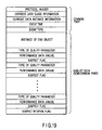
- FIG. 19 shows a concrete example of a performance data message.
- the part from the protocol header to Event Type is for common use.
- the remaining part from the instance of the end object to Suspect Interval Flag is the part that characterizes the individual data items, or cannot be used in common.
- CMIP Common Management Information Protocol
- the size of the common part is large, occupying about 40% of all the bits constituting the message.
- the performance data reported to supervisory control devices M1 to Mn is created by adding each quality data item to one common-use part as shown by the letter B in FIG. 18. This makes it possible to reduce the number of pieces of performance data used for notice.
- the overhead part is also put together, suppressing the length of the message. Consequently, it is possible to reduce the amount of information in notifying the performance data to supervisory control devices M1 to Mn.
- the fourth embodiment puts together the common part that occupied 40% of the total amount of data in the prior art, it reduces the data size remarkably. From these, it is possible to ease the communication burden on the supervisory control devices and the nodes and the burden on the supervisory control devices.
- FIG. 20 shows the configuration of nodes N1 to Nn related to the third embodiment.
- the same parts as those in FIGS. 4, 8, 11, and 14 are indicated by the same reference numerals and only the different parts will be explained.
- each of main-signal circuit boards C1 to Ct includes a reception section 117 and a data memory 118.
- the reception section 117 receives an STM signal.
- the reception signal 117 measures data, such as the communication quality of the STM signal.
- the measured data is supplied to the PD computing section 16 of a sub-circuit board SC via the data memory 118.
- the PD computing section 16 calculates performance data on the basis of the given data.
- the created performance data is supplied via the PD storage section 17 to the PD message creating section 19.
- the message creating section 19 creates a performance data message on the basis of the given performance data.
- a transmission section 119 informs supervisory control devices M1 to Mn of the performance data message.
- each of nodes N1 to Nn includes a timing control section 115 and a timing setting section 116.
- the timing control section 115 changes the timing of notifying the performance data message to supervisory control devices M1 to Mn.
- the timing setting section 116 sets the timing of notifying each performance data message in the timing control section 115 on the basis of the configuration information of its own device stored in the configuration information storage section 114.
- the PD message creating section 19 reads the data from the PD storage section 17 with the timing set in the timing control section 115, creates a performance data message, and notifies the performance data via the main circuit board MC to supervisory control devices M1 to Mn.
- FIG. 21 shows a modification of the fifth embodiment is shown as a sixth embodiment of the present invention.
- the main circuit board MC is provided with the function of creating a performance data message.
- the procedure up to creating performance data is the same as described above.
- the performance data created at the PD computing section 16 is written in the PD storage section 17 of the main circuit board MC.
- the timing setting section 116 gives the timing of notifying the performance data message to the PD message creating section 19.
- the PD message creating section 19 reads each piece of performance data from the PD storage section 17 with the timing set by the timing setting section 116.
- the read-out performance data is notified as a performance data message to supervisory control devices M1 to Mn.
- the timing of notifying each performance data message is set arbitrarily.
- Each performance data message is reported to supervisory control devices M1 to Mn with arbitrarily set timing. That is, in the sixth embodiment, a time lag is given to each performance data message, which is then reported to supervisory control devices M1 to Mn.
- supervisory control devices M1 to Mn exchange various types of information, including performance data, with nodes N1 to Nn.
- nodes N1 to Nn report the performance data to supervisory control devices M1 to Mn, some degree of transmission delay is allowed.
- the alarm information sensed at nodes N1 to Nn must be reported to supervisory control devices immediately after it is sensed.
- the created performance data was notified to supervisory control devices M1 to Mn in such a manner that it was concentrated in a short time.
- the alarm was given, the amount of information became too large and a delay sometimes occurred in the timing of reporting the alarm to supervisory control devices M1 to Mn.
- each node should create performance data at predetermined specific intervals of time.
- Each node unit notifies the supervisory control devices of the periodically created performance data immediately each time the performance data is created. For this reason, in the conventional system, the nodes inform the performance data to the supervisory control devices all at once, regardless of whether the zero suppression function is present or not. As a result, traffic for reporting the performance data may concentrate in a short time.
- the performance data message is notified to supervisory control devices M1 to Mn with random timing.
- the traffic related to the transmission of the performance data message is averaged, which alleviates a delay in reporting the performance data.
- the traffic is liable to concentrate in reporting the performance data.
- the operator of a supervisory control device performs remote control of an arbitrary node, there may be a delay in the response from the node to the operator's act. In such a situation, there is a possibility that erroneous operation or faulty operation may take place.
- the nodes in the sixth embodiment can average the traffic related to information communication between nodes N1 to Nn and supervisory control devices M1 to Mn, the aforementioned disadvantages can be eliminated.
- the present invention is not limited to the above embodiments.
- a system complying with the SDH standard has been used and concrete examples of applying the present invention to the SDH standard have been explained, the invention may be applied to the SONET standard in the U.S. similar to the SDH standard.
- the present invention it is possible to provide a transmission system which has a zero suppression function and is capable of offering information the user needs as much as possible to achieve an improved human-machine interface (HMI), a supervisory control device, and a method of outputting the data in the supervisory control device.
- HMI human-machine interface
- a supervisory control device a supervisory control device
- a method of outputting the data in the supervisory control device it is possible to provide a node which alleviates the burden of communication related to notice of performance data.
- the present invention is effective in the technical field of optical submarine cable systems, particularly in the technical field of networks complying with the SDH and SONET standards.
Landscapes
- Engineering & Computer Science (AREA)
- Computer Networks & Wireless Communication (AREA)
- Signal Processing (AREA)
- Data Exchanges In Wide-Area Networks (AREA)
- Small-Scale Networks (AREA)
Claims (11)
- Système de transmission comprenant une pluralité de noeuds (N1-Nn) formant un réseau et un dispositif de supervision (M1-Mn) destiné à gérer ledit réseau en fonction de données de performance créées au niveau de ces noeuds (N1-Nn), caractérisé en ce que
chacun de ladite pluralité de noeuds (N1-Nn) inclut
un moyen de génération de données de performance (14) destiné à mesurer des éléments de données individuels concernant les éléments de contrôle définis pour une pluralité d'objets à mesurer selon un calendrier spécifique et, en fonction du résultat de la mesure, à créer lesdites données de performance en utilisant une fonction de suppression de zéros consistant à supprimer un succession d'éléments de données de zéro, et
un moyen d'envoi de données de performance (15) destiné à envoyer les données de performance créées au niveau du moyen de génération de données de performance audit dispositif de supervision, et
ledit dispositif de supervision (M1-Mn) inclut
un moyen de réception (23) destiné à recevoir les données de performance envoyées depuis lesdits noeuds (N1-Nn),
un moyen de stockage (27) destiné à accumuler un historique des données de performance reçues,
un moyen d'interface utilisateur (80) destiné à accepter la demande de sortie de données de l'utilisateur avec des conditions de récupération spécifiées incluant un intervalle de temps et à sortir les données correspondant à la demande, et
un moyen de commande de sortie (22) qui détermine la raison pour laquelle les données de performance sont absentes, lorsque les données de performance qui devraient être présentes dans ledit moyen de stockage (27) selon ledit calendrier sont absentes dans l'intervalle de temps spécifié dans lesdites conditions de récupération lors de l'acquisition des données de performance correspondant auxdites conditions de récupération depuis ledit moyen de stockage (27), et si la raison est l'exécution de la suppression de zéros au niveau dudit moyen de génération de données de performance (14), donne à l'élément de données lié aux données de performance absentes la valeur zéro, et qui crée ensuite des données pour une sortie au niveau dudit moyen d'interface utilisateur (80) en fonction desdites données de performance acquises et amène ledit moyen d'interface utilisateur (80) à sortir les données créées. - Système de transmission selon la revendication 1, caractérisé en ce que chacun desdits noeuds (N1-Nn) inclut
un moyen de sous-stockage (12) destiné à accumuler un historique des données de performance créées au niveau dudit moyen de génération de données de performance (14), et
ledit dispositif de supervision (M1-Mn) inclut
un moyen d'acquisition de données de performance (221B) destiné à acquérir les données de performance créées au niveau desdits noeuds (N1-Nn) et à stocker les informations dans le moyen de stockage (27) de son propre dispositif, et
un moyen d'acquisition de données manquantes (227) destiné, lorsqu'il y a un manque dans les données de performance stockées dans le moyen de stockage (27) de son propre dispositif, à acquérir les données de performance manquantes depuis le moyen de sous-stockage (12) dudit noeud (N1-Nn) et à les stocker dans le moyen de stockage (27) de son propre dispositif. - Système de transmission selon la revendication 1 ou 2, caractérisé en ce que ledit moyen de commande de sortie (22) inclut
un moyen de gestion de temps (2210) destiné à mettre à jour et à stocker le temps Tc auquel ledit moyen de réception (23) a reçu les données de performance pour la dernière fois,
un moyen d'acquisition de période (223) destiné à acquérir une période T1 dans laquelle lesdites données sont mesurées au niveau dudit moyen de génération de données de performance (14),
un premier moyen de jugement (222) destiné à juger si le temps auquel les données de performance doivent être créées dans ladite période T1 est présent entre Tc et T en fonction du fait que l'expression T - Tc > T1 est valable ou non, tant que le temps le plus proche du temps présent dans l'intervalle de temps spécifié dans lesdites conditions de récupération est T,
un moyen d'acquisition de nombre d'omissions (229) destiné, si le premier moyen de jugement (222) a jugé que le temps auquel les données de performance doivent être créées est présent, à acquérir le nombre Ns de fois où la création des données de performance a été omise par ladite fonction de suppression de zéros,
un second moyen de jugement (225) destiné à juger si l'exécution de la suppression de zéros est présente ou absente en fonction du fait que l'expression Ns•T1<T-Tc≤(Ns+1)•T1 est valable ou non, et
un moyen de création de données de sortie (226) destiné, si le second moyen de jugement (225) a jugé que l'exécution de la suppression de zéros est présente, à donner à l'élément de données lié auxdites données de performance absentes la valeur zéro et à créer des données pour une sortie au niveau dudit moyen d'interface utilisateur (80) en fonction desdites données de performance de lecture et à amener ledit moyen d'interface utilisateur (80) à sortir les données créées. - Dispositif de supervision (M1-Mn) destiné à gérer un réseau composé d'une pluralité de noeuds (N1-Nn) en fonction des données de performance créées au niveau de chaque noeud (N1-Nn), chacun de ladite pluralité de noeuds (N1-Nn) incluant un moyen de génération de données de performance (14) destiné à mesurer des éléments de données individuels concernant les éléments de contrôle définis pour une pluralité d'objets à mesurer selon un calendrier spécifique et, en fonction du résultat de la mesure, à créer lesdites données de performance en utilisant une fonction de suppression de zéros consistant à supprimer une succession d'éléments de données de zéro, ledit dispositif de supervision (M1-Mn) étant caractérisé en ce qu'il comprend :un moyen de stockage (27) destiné à stocker un historique desdites données de performance créées ;un moyen d'interface utilisateur (80) destiné à accepter la demande de sortie de données de l'utilisateur avec des conditions de récupération spécifiées pour lesdites données de performance incluant au moins un intervalle de temps et à sortir les données de performance correspondant à la demande, etun moyen de commande de sortie (22) qui détermine la raison pour laquelle les données de performance sont absentes, lorsque les données de performance qui devraient être présentes selon ledit calendrier sont absentes dans l'intervalle de temps spécifié dans lesdites conditions de récupération lors de l'acquisition des données de performance correspondant auxdites conditions de récupération de données de performance depuis ledit moyen de stockage (27), et si la raison est l'exécution de la suppression de zéros au niveau dudit moyen de génération de données de performance (14), donne à l'élément de données lié aux données de performance absentes la valeur zéro, et qui crée ensuite des données pour une sortie au niveau dudit moyen d'interface utilisateur (80) en fonction des données de performance acquises et amène ledit moyen d'interface utilisateur (80) à sortir les données créées.
- Dispositif de supervision (M1-Mn) selon la revendication 4, caractérisé en ce que chacun desdits noeuds (N1-Nn) inclut
un moyen de sous-stockage (12) destiné à accumuler un historique des données de performance créées au niveau dudit moyen de génération de données de performance (14),
un moyen d'acquisition de données de performance (221B) destiné à acquérir les données de performance créées au niveau desdits noeuds (N1-Nn) et à les stocker dans le moyen de stockage (27) de son propre dispositif, et
un moyen d'acquisition de données manquantes (227) destiné, lorsqu'il y a un manque dans les données de performance stockées dans le moyen de stockage (27) de son propre dispositif, à acquérir les données de performance manquantes depuis le moyen de sous-stockage (12) dudit noeud (N1-Nn) et à les stocker dans le moyen de stockage (27) de son propre dispositif. - Dispositif de supervision (M1-Mn) selon la revendication 4 ou 5, caractérisé en ce que ledit moyen de commande de sortie (22) inclut
un moyen de gestion de temps (2210) destiné à mettre à jour et à stocker le temps Tc auquel ledit moyen de réception (23) a reçu les données de performance pour la dernière fois,
un moyen d'acquisition de période (223) destiné à acquérir une période T1 dans laquelle lesdites données sont mesurées au niveau dudit moyen de génération de données de performance (14),
un premier moyen de jugement (222) destiné à juger si le temps auquel les données de performance doivent être créées dans ladite période T1 est présent entre Tc et T en fonction du fait que l'expression T-Tc>T1 est valable ou non, tant que le temps le plus proche du temps présent dans l'intervalle de temps spécifié dans lesdites conditions de récupération est T,
un moyen d'acquisition de nombre d'omissions (229) destiné, si le premier moyen de jugement (222) a jugé que le temps auquel les données de performance doivent être créées est présent, à acquérir le nombre Ns de fois où la création des données de performance a été omise par ladite fonction de suppression de zéros,
un second moyen de jugement (225) destiné à juger si l'exécution de la suppression de zéros est présente ou absente en fonction du fait que l'expression Ns•T1<T-Tc=(Ns+1)•T1 est valable ou non, et
un moyen de création de données de sortie (226) destiné, si le second moyen de jugement (225) a jugé que l'exécution de la suppression de zéros est présente, à donner à l'élément de données lié auxdites données de performance absentes la valeur zéro et à créer des données pour une sortie au niveau dudit moyen d'interface utilisateur (80) en fonction desdites données de performance de lecture et à amener ledit moyen d'interface utilisateur (80) à sortir les données créées. - Procédé de sortie de données implémenté dans un dispositif de supervision (M1-Mn) qui gère un réseau composé d'une pluralité de noeuds (N1-Nn) destinés à mesurer des éléments de données individuels concernant les éléments de contrôle définis pour une pluralité d'objets à mesurer selon un calendrier spécifique et, en fonction du résultat de la mesure, à créer lesdites données de performance en utilisant une fonction de suppression de zéros consistant à supprimer une succession d'éléments de données de zéro, et qui inclut un moyen de stockage (27) destiné à accumuler un historique desdites données de performance créées, ledit procédé de sortie de données comprenant :une première étape (S6, S21) consistant à, en réponse à l'opération de demande de sortie de données dans des conditions de récupération spécifiées incluant au moins un intervalle de temps, juger la présence ou l'absence de la possibilité que le caractère indéfini se produise dans les données sorties dans ledit intervalle de temps spécifié ;une seconde étape (S8, S23) consistant à déterminer la raison, si l'on juge lors de la première étape (S6, S21) qu'il y a une possibilité que ladite colonne indéfinie se produise ; etune troisième étape (S11, S25) consistant à insérer des 0 dans la colonne indéfinie et ainsi à restructurer les données à fournir à un processus de sortie, si l'on juge lors de la seconde étape (S6, S21) que la raison de la survenue de ladite colonne indéfinie est l'exécution de ladite fonction de suppression de zéros.
- Procédé de sortie de données selon la revendication 7, dans lequel ladite première étape (S6, S21) acquiert le temps Tc auquel les données de performance ont été créées pour la dernière fois et la période T1 dans laquelle les données de qualité sont totalisées au niveau dudit noeud (N1-Nn), et juge la présence ou l'absence de la possibilité que ladite colonne indéfinie se produise en fonction du fait que l'expression T-Tc>T1 est valable ou non, tant que le temps le plus proche du temps présent dans l'intervalle de temps spécifié dans lesdites conditions de récupération est T, et
ladite seconde étape (S8, S23) acquiert le nombre Ns de fois où la création des données de performance a été omise par ladite fonction de suppression de zéros au niveau dudit noeud (N1-Nn) et détermine la raison de la survenue de ladite colonne indéfinie en vérifiant si l'expression Ns•Ti<T-Tc=(Ns+1)•T1 est valable ou non. - Procédé de sortie de données selon la revendication 8, caractérisé en ce qu'il comprend en outre une quatrième étape (S28) consistant à, si T-Tc>(Ns+1) )•T1 est valable à ladite seconde étape (S8, S23), considérer les données de performance à stocker dans ledit moyen de stockage (27) comme ayant un manque et à stocker les données de performance.
- Réseau comprenant une pluralité de noeuds (N1-Nn) qui sont connectés via un circuit de communication (OF) et qui transmettent des données de communication sur le réseau, caractérisé en ce que chacun desdits noeuds (N1-Nn) a :un moyen de génération de données de performance (16) destiné à mesurer des éléments de données individuels concernant les éléments de contrôle définis pour une pluralité d'objets à mesurer selon un calendrier spécifique et, en fonction du résultat de la mesure, à créer des données de performance, etun moyen de création de message (19, 113) destiné à diviser les éléments de données formant lesdites données de performance en parties communes aux données individuelles de performance et en parties non communes aux données individuelles de performance, et à ajouter une pluralité de parties non communes à une partie commune pour créer un message de données de performance.
- Réseau selon la revendication 10, caractérisé en outre par :un moyen de notification (119) destiné à notifier les données de performance créées par le moyen de génération de données de performance (16) audit dispositif de supervision (M1-Mn) ; etun moyen de définition de synchronisation (116) destiné à définir la synchronisation pour le moyen de notification pour notifier les données de performance pour chaque donnée de performance selon les informations de configuration concernant son propre dispositif.
Applications Claiming Priority (2)
| Application Number | Priority Date | Filing Date | Title |
|---|---|---|---|
| JP2000043206 | 2000-02-21 | ||
| JP2000043206 | 2000-02-21 |
Publications (3)
| Publication Number | Publication Date |
|---|---|
| EP1128601A2 EP1128601A2 (fr) | 2001-08-29 |
| EP1128601A3 EP1128601A3 (fr) | 2001-09-12 |
| EP1128601B1 true EP1128601B1 (fr) | 2006-07-19 |
Family
ID=18566159
Family Applications (1)
| Application Number | Title | Priority Date | Filing Date |
|---|---|---|---|
| EP01301487A Expired - Lifetime EP1128601B1 (fr) | 2000-02-21 | 2001-02-20 | Système de transmission, dispositif de supervison, procedé pour sortir des données dans le dispositif et des noeuds pour transmettre dans le système |
Country Status (3)
| Country | Link |
|---|---|
| US (1) | US6973045B2 (fr) |
| EP (1) | EP1128601B1 (fr) |
| DE (1) | DE60121489T2 (fr) |
Families Citing this family (6)
| Publication number | Priority date | Publication date | Assignee | Title |
|---|---|---|---|---|
| US7054264B2 (en) * | 2001-07-24 | 2006-05-30 | Corrigent Systems Ltd. | Interconnect and gateway protection in bidirectional ring networks |
| EP1298840A1 (fr) * | 2001-09-28 | 2003-04-02 | Siemens Aktiengesellschaft | Gestion de la performance d'un réseau |
| US7274731B2 (en) * | 2001-11-09 | 2007-09-25 | Adc Dsl Systems, Inc. | Non-chronological system statistics |
| JP2005250671A (ja) * | 2004-03-02 | 2005-09-15 | Sony Corp | 通信システム、通信装置、通信方法およびプログラム |
| US20060098578A1 (en) * | 2004-11-08 | 2006-05-11 | Sbc Knowledge Ventures, L.P. | System and method for converting autonomous PM data into periodic PM data |
| CN112213993A (zh) * | 2019-07-11 | 2021-01-12 | 航天长征化学工程股份有限公司 | 一种基于云端的控制系统和方法 |
Family Cites Families (6)
| Publication number | Priority date | Publication date | Assignee | Title |
|---|---|---|---|---|
| US5864608A (en) * | 1996-06-26 | 1999-01-26 | Mci Communications Corporation | System and method for formatting performance data in a telecommunications system |
| US5781703A (en) * | 1996-09-06 | 1998-07-14 | Candle Distributed Solutions, Inc. | Intelligent remote agent for computer performance monitoring |
| US6069875A (en) * | 1997-12-31 | 2000-05-30 | Alcatel Usa Sourcing, L.P. | Performance monitoring multiplexer module for packaging PM data |
| US6678250B1 (en) * | 1999-02-19 | 2004-01-13 | 3Com Corporation | Method and system for monitoring and management of the performance of real-time networks |
| US6785285B1 (en) * | 1999-06-03 | 2004-08-31 | Fujitsu Network Communications, Inc. | Method and system for providing broadcast channels over an emulated subnetwork |
| US6765864B1 (en) * | 1999-06-29 | 2004-07-20 | Cisco Technology, Inc. | Technique for providing dynamic modification of application specific policies in a feedback-based, adaptive data network |
-
2001
- 2001-02-20 DE DE60121489T patent/DE60121489T2/de not_active Expired - Lifetime
- 2001-02-20 EP EP01301487A patent/EP1128601B1/fr not_active Expired - Lifetime
- 2001-02-21 US US09/788,592 patent/US6973045B2/en not_active Expired - Fee Related
Also Published As
| Publication number | Publication date |
|---|---|
| DE60121489D1 (de) | 2006-08-31 |
| EP1128601A3 (fr) | 2001-09-12 |
| US20010015961A1 (en) | 2001-08-23 |
| EP1128601A2 (fr) | 2001-08-29 |
| US6973045B2 (en) | 2005-12-06 |
| DE60121489T2 (de) | 2007-03-29 |
Similar Documents
| Publication | Publication Date | Title |
|---|---|---|
| USRE37401E1 (en) | Fault recovery system of a ring network | |
| US5615211A (en) | Time division multiplexed backplane with packet mode capability | |
| US7142516B2 (en) | Performance monitoring of high speed communications networks | |
| WO1996041440A1 (fr) | Procede et systeme de localisation de defaillances dans un reseau de communications | |
| US5878095A (en) | Hierarchical synchronization method | |
| EP0898398B1 (fr) | Méthode et appareil pour re-synchroniser un gestionnaire de réseau à ses agents de réseau | |
| US5506839A (en) | Congestion control method, terminal adapter using the method and communications system using the terminal adapter | |
| US5875172A (en) | Automatic transmission network restoring system | |
| WO2000016510A9 (fr) | Transformation de signaux servant a localiser les pannes | |
| EP0748547B1 (fr) | Procede de synchronisation hierarchisee | |
| EP1128601B1 (fr) | Système de transmission, dispositif de supervison, procedé pour sortir des données dans le dispositif et des noeuds pour transmettre dans le système | |
| US7158721B2 (en) | Performance monitoring of multiple channels in an automatic protection switched network | |
| US5636204A (en) | Transmission fault processing method and transmisssion fault processing device | |
| US5796793A (en) | Hierarchical synchronization method | |
| US6058120A (en) | System and apparatus for controlling telecommunications components | |
| US6128284A (en) | SDH-communication-network/already existing communication network monitoring and integrating apparatus and its method | |
| EP0308450B1 (fr) | Reglage de l'instabilite de signaux numeriques dans des liaisons de communication | |
| US5822298A (en) | Ring transmission system for providing efficient transmission of management data | |
| JP3898453B2 (ja) | 伝送システム、監視制御装置、データ出力方法、およびノード装置 | |
| KR100251680B1 (ko) | 비동기 전송모드 망에서 보수운용관리 고장상태 처리방법 및장치 | |
| JP3523427B2 (ja) | データ交換装置 | |
| JP2993356B2 (ja) | 通信システムの障害監視システム | |
| US6870829B1 (en) | Message signalling in a synchronous transmission apparatus | |
| Logothetis et al. | The effect of detection and restoration times for error recovery in communication networks | |
| US6256316B1 (en) | Communication method in centralized supervisory system |
Legal Events
| Date | Code | Title | Description |
|---|---|---|---|
| PUAI | Public reference made under article 153(3) epc to a published international application that has entered the european phase |
Free format text: ORIGINAL CODE: 0009012 |
|
| PUAL | Search report despatched |
Free format text: ORIGINAL CODE: 0009013 |
|
| 17P | Request for examination filed |
Effective date: 20010309 |
|
| AK | Designated contracting states |
Kind code of ref document: A2 Designated state(s): DE FR GB Kind code of ref document: A2 Designated state(s): AT BE CH CY DE DK ES FI FR GB GR IE IT LI LU MC NL PT SE TR |
|
| AX | Request for extension of the european patent |
Free format text: AL;LT;LV;MK;RO;SI |
|
| AK | Designated contracting states |
Kind code of ref document: A3 Designated state(s): AT BE CH CY DE DK ES FI FR GB GR IE IT LI LU MC NL PT SE TR |
|
| AX | Request for extension of the european patent |
Free format text: AL;LT;LV;MK;RO;SI |
|
| AKX | Designation fees paid |
Free format text: DE FR GB |
|
| 17Q | First examination report despatched |
Effective date: 20040303 |
|
| GRAP | Despatch of communication of intention to grant a patent |
Free format text: ORIGINAL CODE: EPIDOSNIGR1 |
|
| GRAS | Grant fee paid |
Free format text: ORIGINAL CODE: EPIDOSNIGR3 |
|
| GRAA | (expected) grant |
Free format text: ORIGINAL CODE: 0009210 |
|
| AK | Designated contracting states |
Kind code of ref document: B1 Designated state(s): DE FR GB |
|
| REG | Reference to a national code |
Ref country code: GB Ref legal event code: FG4D |
|
| REF | Corresponds to: |
Ref document number: 60121489 Country of ref document: DE Date of ref document: 20060831 Kind code of ref document: P |
|
| ET | Fr: translation filed | ||
| REG | Reference to a national code |
Ref country code: GB Ref legal event code: 746 Effective date: 20070317 |
|
| PLBE | No opposition filed within time limit |
Free format text: ORIGINAL CODE: 0009261 |
|
| STAA | Information on the status of an ep patent application or granted ep patent |
Free format text: STATUS: NO OPPOSITION FILED WITHIN TIME LIMIT |
|
| 26N | No opposition filed |
Effective date: 20070420 |
|
| PGFP | Annual fee paid to national office [announced via postgrant information from national office to epo] |
Ref country code: FR Payment date: 20110218 Year of fee payment: 11 Ref country code: DE Payment date: 20110216 Year of fee payment: 11 |
|
| PGFP | Annual fee paid to national office [announced via postgrant information from national office to epo] |
Ref country code: GB Payment date: 20110216 Year of fee payment: 11 |
|
| GBPC | Gb: european patent ceased through non-payment of renewal fee |
Effective date: 20120220 |
|
| REG | Reference to a national code |
Ref country code: FR Ref legal event code: ST Effective date: 20121031 |
|
| REG | Reference to a national code |
Ref country code: DE Ref legal event code: R119 Ref document number: 60121489 Country of ref document: DE Effective date: 20120901 |
|
| PG25 | Lapsed in a contracting state [announced via postgrant information from national office to epo] |
Ref country code: GB Free format text: LAPSE BECAUSE OF NON-PAYMENT OF DUE FEES Effective date: 20120220 Ref country code: FR Free format text: LAPSE BECAUSE OF NON-PAYMENT OF DUE FEES Effective date: 20120229 |
|
| PG25 | Lapsed in a contracting state [announced via postgrant information from national office to epo] |
Ref country code: DE Free format text: LAPSE BECAUSE OF NON-PAYMENT OF DUE FEES Effective date: 20120901 |