EP1128609B1 - Automate de classification de paquets - Google Patents
Automate de classification de paquets Download PDFInfo
- Publication number
- EP1128609B1 EP1128609B1 EP00310753A EP00310753A EP1128609B1 EP 1128609 B1 EP1128609 B1 EP 1128609B1 EP 00310753 A EP00310753 A EP 00310753A EP 00310753 A EP00310753 A EP 00310753A EP 1128609 B1 EP1128609 B1 EP 1128609B1
- Authority
- EP
- European Patent Office
- Prior art keywords
- entry
- packet classification
- criterion
- memory
- rule
- Prior art date
- Legal status (The legal status is an assumption and is not a legal conclusion. Google has not performed a legal analysis and makes no representation as to the accuracy of the status listed.)
- Expired - Lifetime
Links
- 230000015654 memory Effects 0.000 claims description 139
- 150000001875 compounds Chemical class 0.000 claims description 2
- 230000004044 response Effects 0.000 claims 2
- 238000001914 filtration Methods 0.000 description 29
- 238000010586 diagram Methods 0.000 description 17
- 230000009471 action Effects 0.000 description 15
- 239000004744 fabric Substances 0.000 description 14
- 238000000034 method Methods 0.000 description 11
- 238000012545 processing Methods 0.000 description 9
- 230000006870 function Effects 0.000 description 7
- 230000027455 binding Effects 0.000 description 6
- 238000009739 binding Methods 0.000 description 6
- 230000008569 process Effects 0.000 description 6
- 238000012546 transfer Methods 0.000 description 6
- 230000003287 optical effect Effects 0.000 description 3
- 230000008901 benefit Effects 0.000 description 2
- 239000000872 buffer Substances 0.000 description 2
- 230000003139 buffering effect Effects 0.000 description 2
- 238000004891 communication Methods 0.000 description 2
- 230000002708 enhancing effect Effects 0.000 description 2
- 230000000873 masking effect Effects 0.000 description 2
- 208000020968 mature T-cell and NK-cell non-Hodgkin lymphoma Diseases 0.000 description 2
- 230000011218 segmentation Effects 0.000 description 2
- 208000003251 Pruritus Diseases 0.000 description 1
- 230000002457 bidirectional effect Effects 0.000 description 1
- 230000008859 change Effects 0.000 description 1
- 230000000593 degrading effect Effects 0.000 description 1
- 230000001419 dependent effect Effects 0.000 description 1
- 238000011156 evaluation Methods 0.000 description 1
- 238000009432 framing Methods 0.000 description 1
- 238000012986 modification Methods 0.000 description 1
- 230000004048 modification Effects 0.000 description 1
- 238000012544 monitoring process Methods 0.000 description 1
- 230000008520 organization Effects 0.000 description 1
- 230000004043 responsiveness Effects 0.000 description 1
- 238000000926 separation method Methods 0.000 description 1
- 230000011664 signaling Effects 0.000 description 1
Images


Classifications
-
- H—ELECTRICITY
- H04—ELECTRIC COMMUNICATION TECHNIQUE
- H04L—TRANSMISSION OF DIGITAL INFORMATION, e.g. TELEGRAPHIC COMMUNICATION
- H04L47/00—Traffic control in data switching networks
- H04L47/10—Flow control; Congestion control
- H04L47/24—Traffic characterised by specific attributes, e.g. priority or QoS
- H04L47/2441—Traffic characterised by specific attributes, e.g. priority or QoS relying on flow classification, e.g. using integrated services [IntServ]
-
- H—ELECTRICITY
- H04—ELECTRIC COMMUNICATION TECHNIQUE
- H04L—TRANSMISSION OF DIGITAL INFORMATION, e.g. TELEGRAPHIC COMMUNICATION
- H04L47/00—Traffic control in data switching networks
- H04L47/10—Flow control; Congestion control
-
- H—ELECTRICITY
- H04—ELECTRIC COMMUNICATION TECHNIQUE
- H04L—TRANSMISSION OF DIGITAL INFORMATION, e.g. TELEGRAPHIC COMMUNICATION
- H04L47/00—Traffic control in data switching networks
- H04L47/10—Flow control; Congestion control
- H04L47/43—Assembling or disassembling of packets, e.g. segmentation and reassembly [SAR]
Definitions
- the present invention is related to the field of data communication networks.
- network devices such as switches are used to route packets through the network.
- Each switch typically has a number of line interfaces, each connected to a different network segment.
- forwarding logic determines which line interface the packet should be transmitted from, and the packet is transferred to the appropriate outgoing line interface to be sent toward its destination in the network.
- Packet filtering can be used to achieve various network management goals, such as traffic monitoring and security goals. Filtering criteria are established by network administrators, and provided to the switches or other devices that carry out the filtering operation. Packets received by the switches are examined to determine whether their characteristics match the criteria for any of the established filters. For packets that satisfy the criteria for one or more filters, predetermined actions associated with those filters are carried out. For example, under certain circumstances it may be desirable that packets originating from a given network node be discarded rather than being forwarded in the network.
- a filter can be defined in which the criterion is that a packet source address exactly match a specific value, which is the address of the node whose packets are to be discarded. The action associated with the filter is the discarding of the packet. When a packet is received whose source address satisfies this criterion, it is discarded rather than being forwarded in the normal fashion.
- criteria include exact matches as well as range checking, i.e., checking whether a value in a packet falls in some range of values.
- Numerous packet parameters can be used as criteria, such as source address, destination address, port identifiers, type of service, and others. To be useful, packet filtering processes must allow filters to be flexibly defined using different combinations of these and other criteria.
- Bannatyne R et al "Introduction to microcontrollers" WESCON/97. Conference Proceedings Santa Clara, CA, USA 4-6 Nov. 1997, New York, NY, USA, IEEE, US, 4 November 1997 (1997-11-04), pages 564-574, provides a basic introduction to the components and functions of a microcontroller.
- WO-A-99 00 935 discloses a multi-layered network element for forwarding received packets from an input port to one or more output ports.
- Apparatus according to the invention is as set out in claim 1. Preferred forms are set out in the dependent claims.
- packet processing logic in a network device that provides high-speed packet classification for packet filtering purposes.
- the architecture of the classification apparatus provides substantial flexibility in the definition of complex filter criteria- Robust filtering can be performed at a sufficiently high rate to avoid degrading packet forwarding performance.
- the packet classification apparatus includes a rule memory and a criterion memory.
- One type of rule memory entry contains an operator and a pointer to a criterion memory entry.
- the operator defines a comparison operation to be performed, such as EQUAL (exact match) or LESS THAN.
- the criterion memory entry contains one or more values to be used as comparands on one side of the comparison, where corresponding values from a received packet appear on the other side of the comparison.
- one comparand from criterion memory may represent a source address. This value is compared with the value appearing in the source address field of received packets.
- Control logic responds to packet classification requests to retrieve a rule memory entry from the rule memory, retrieve the criterion memory entry identified by the criterion memory pointer in the rule memory entry, and perform the operation specified by the operator in the rule memory entry on the values in the criterion memory entry and corresponding values included in the classification request. This procedure is repeated for a sequence of rule memory entries until a certain ending condition is encountered, whereupon a packet classification result is generated reflecting the result of the classification operations. This result is provided to a packet processor to take theappropriate action based on the classification result.
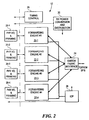
- a network switch 10 is shown as including a number of line interfaces 12 connected to respective network segments 14.
- the line interfaces 12 are connected to a switch fabric 16 used to provide connections among the line interfaces 12 for packet forwarding.
- the overall operation of the switch 10, including the dynamic configuration of the switch fabric 16, is controlled by a switch control 18.
- the various network segments 14 may be of different types.
- certain of the network segments 14 may be optical links operating at any of a variety of standard signalling rates, such as OC-3/STM-1 and OC-12/STM-4.
- Others of the network segments 14 may be non-optical links employing coaxial cable, for example, and carrying signals of different formats.
- Each line interface 12 is of course designed for operation with the specific type of network segment 14 to which it connects.
- the primary tasks of each line interface 12 are to transfer packets or frames received from an attached network segment 14 to another line interface 12 via the switch fabric 16 for forwarding on a network segment 14 attached to the other line interface 12, and to receive packets from the other line interfaces 12 via the switch fabric 16 for forwarding on the attached network segment 14.
- FIG. 2 shows the structure of one type of line interface 12.
- This interface contains four separate optical interface ports, each including physical input/output and framing circuitry 20 and a forwarding engine 22.
- the forwarding engines 22 are all connected to switch fabric interface logic 24, which interfaces with the switch fabric 16 of Figure 1.
- the forwarding engines also interface with a line interface I/O processor (IOP) 26.
- IOP line interface I/O processor
- Timing control logic 28 and DC power circuitry 30 are also included.
- Each forwarding engine 22 provides a bidirectional data path between a connected physical I/O block 20 and the switch fabric interface 24.
- Received packets are segmented into multiple fixed-size ATM-like cells for transfer through the switch fabric 16 of Figure I to another line interface 12.
- Cells received from the switch fabric 16 via the switch fabric interface 24 are reassembled into packets for outgoing transfer to the connected physical I/O block 20.
- the IOP 26 is a general-purpose processor that performs background functions, i.e. functions that support the forwarding of packets that are not carried out on a per-packet basis.
- One function performed by the IOP 26 is receiving packet forwarding information and packet filtering information from the switch control 18 of Figure 1, and distributing the information to the forwarding engines 22. This process is described below.
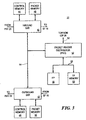
- FIG. 3 shows a block diagram of a forwarding engine 22.
- An inbound segmentation-and-reassembly (SAR) logic block 40 provides a data path from a physical I/O block 20 to the switch fabric 16 of Figure 2, and an outbound SAR logic block 42 provides a data path from the switch fabric 16 to the respective physical I/O block 20.
- SAR 40, 42 is coupled to a respective control memory 44, 46 and packet memory 48, 50 used in performing the segmentation or reassembly function.
- the SAR devices 40 and 42 are both connected to a packet header distributor (PHD) application-specific integrated circuit (ASIC) 52 via a 64-bit PCI bus 54.
- PHD packet header distributor
- ASIC application-specific integrated circuit
- the PHD ASIC 52 provides FIFO queue interfaces between the PCI bus 54 and a separate 64-bit bus 56.
- the bus 56 connects the PHD ASIC 52 with a forwarding processor (FP) 58 and forwarding processor memory 60.
- FP forwarding processor
- the PHD ASIC 52 is also connected to the IOP 26 of Figure 2 by a separate bus 62.
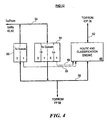
- FIG. 4 shows the structure of the PHD 52 of Figure 3.
- a set of receive queues or RX queues 64 is used for temporary buffering of packet headers and other messages bound for the FP 58.
- there are four RX queues 64 two queues for high-priority traffic and two queues for low-priority traffic.
- An example of high-priority traffic is traffic having a high Quality of Service (QOS) guarantee, such as a committed rate.
- QOS Quality of Service
- Low-priority traffic is traffic having a lower QOS or no QOS guarantee, such as best-efforts.
- QOS Quality of Service
- a set of transmit queues or TX queues 66 is used for temporary buffering of packet headers and other messages bound for the SARs 40, 42 from the FP 58.
- a route and classification engine 68 performs a route lookup and various packet filtering checks on behalf of the FP 58. The packet filtering operation is described below.
- the route and classification engine 68 receives status information from the queues 64, 66 via signal lines 69, and makes this information available to the FP 58 in a manner described below.
- Packets are received by the inbound SAR 40 from the associated physical-layer circuitry 20 of Figure 2, and are stored in the packet memory 48.
- the inbound SAR 40 transfers the packet headers to an appropriate one of the RX queues 64 in the PHD 52.
- the FP 58 polls the PHD 52 to determine queue status, and retrieves the packet headers from the RX queues 64 as appropriate.
- the FP 58 sends certain information elements from each header to the route and classification engine 68 in a route and classification request.
- the route and classification engine 68 performs a route lookup and various packet filtering checks against the header elements in the request, and places the results of these checks into a result queue (described below).
- the FP 58 obtains the route lookup and classification results from the result queue, and uses these results to create a new header for the packet.
- the new header is transferred back to the PHD 52 via one of the TX queues 66, along with information identifying the internal circuit on which the packet should be forwarded after segmentation.
- the inbound SAR 40 retrieves the new header, places it in the packet memory 48 with the payload portion of the received packet, segments the new packet and transfers the resulting cells to the switch fabric 16 of Figure I on the internal circuit specified by the FP 58.
- the outbound SAR 42 receives packets from the switch fabric 16 of Figure 1, and reassembles these packets into the packet memory 50. Packet headers are sent to the PHD 52, and retrieved from the PHD 52 by the FP 58. For most packets, the route lookup and filtering checks will have already been performed during inbound processing, so these operations are not repeated. Some protocols, however, do require lookups and filtering for both inbound and outbound packets, and therefore these operations are optionally performed by the FP 58 in conjunction with the route and classification engine 68. If appropriate, the FP 58 formulates a new header for the packet, based in part on the identity of the internal circuit on which the segmented outbound packet is received.
- This new header is written to the PHD 52, along with transmit circuit information.
- the PHD 52 transfers the new header to the outbound SAR 42.
- the outbound SAR 42 places the new header in the packet memory 50 along with the packet payload, and transmits the packet to the associated physical layer interface 20 of Figure 2.
- FIG. 5 shows the structure of the route and classification engine 68.
- Requests from the FP 58 of Figure 3 are placed into a single request queue 70, and results are returned in a single result queue 72.
- Each queue 70 and 72 holds up to 16 request/result entries.
- a route lookup engine (RLE) 74 performs route lookups, typically based on a destination address (DA) included in the header.
- a packet classification engine (PCE) 76 performs packet filtering checks, based on specified information included in the packet header. The operation of the PCE 76 is described in more detail below.
- Input FIFO buffers 78 are placed between the request queue 70 and the RLE 74 and PCE 76, and output FIFO buffers 80 are placed between the RLE 74 and PCE 76 and the result queue 72.
- the FIFOs 78 and 80 provide a measure of decoupling between the processing performed by the RLE 74 and the processing performed by the PCE 76.
- a multiplexer 81 enables the FP 58 to read either the result queue 72, or status information including status from the request queue 70, the result queue 72, and the status appearing on the signal lines 69 of Figure 4. The structure of these entries is described below.
- Figure 6 shows the structure of the route and classification request that is passed to the PCE 76 and RLE 74 via the request queue 70 of Figure 5.
- the size of the request is four 64-bit words.
- IP TOS Type of Service
- TCP Flags The contents of the TCP Flags field of the received packet IP Source Address The IP Source Address of the received packet IP Dest. Addr.
- IP Destination Address of the received packet TCP/UDP Source Port The identifier of the TCP/UDP port on which the packet was received - TCP/UDP Dest. Port The identifier of the TCP/UDP port for which the received packet is destined Reserved Unused reserved bits
- the appropriate fields of the request are provided to the respective input FIFOs 78 for the RLE 74 and PCE 76 of Figure 5.
- Some of the fields, such as the Req. ID and the IP Dest. Addr., are provided to both the RLE 74 and the PCE 76.
- Other fields are provided to only one or the other. The use of the fields routed to the PCE in particular is described below.
- Figure 7 and Figure 8 show the respective structures of the two different types of entries that are read from the route and classification engine 68 of Figure 4.
- Figure 7 shows a result entry, which is obtained from the result queue 72 of Figure 5 and conveys the result of a classification search.
- Figure 8 shows a status entry used to convey status information to the FP 58 of Figure 3.
- the fields of the status entry shown in Figure 8 are defined as follows: FIELD NAME DESCRIPTION Zero Unused, set to zero TX Message Remaining space in forwarding-processor-to-IOP message queue RCE Results Number of pending entries in result queue 72. Normally zero, because status inserted only when queue is empty. RCE Requests Number of empty entries in request queue 70 Tx-0 ⁇ Number of empty entries Tx-1 ⁇ in TX queues 66. Hi-0 ⁇ Hi-1
- the FP 58 of Figure 3 writes lookup and classification requests to the request queue 70.
- different information elements from the request are written simultaneously into the respective input FIFOs 78 for the RLE 74 and the PCE 76.
- the RLE 74 and PCE 76 operate on the separate pieces of each request independently, and in general finish their respective processing operations for a given request at different times.
- the results of these operations are written to the output FIFOs 80.
- both sets of results for a given packet have reached the front of the output FIFOs 80, a single combined result is written to the result queue 72.
- the combined results are read by the FP 58 and used to formulate new packet headers and circuit information for the SARs 40 and 42 of Figure 3, as discussed above.
- the FP 68 uses the route and classification engine 68 in a batch fashion. When there is sufficient room in the request queue 70, a burst of requests are written. Respective portions of each request are handled by the PCE 76 and RLE 74, as previously mentioned.
- the FP obtains results by issuing a read command to the RCE 68. For each read, a block of four 64-bit entries are returned to the FP 58 via the FP bus 56. Each block contains as many results from the result queue 72 as are available at the time of the read, and a number of status entries as padding. Thus, one of five different combinations of entries in a result block may be read:
- the FP 58 will generally issue read commands until the result queue 72 is empty, which is inferred whenever one or more status entries are included in the result block. The FP 58 then uses these results while the route and classification engine 68 processes the next batch of requests. The FP 58 uses the status information to manage the flow of requests, so that the RLE 74 and PCE 76 are kept busy and the queues 70 and 72 and FIFOs 78 and 80 are prevented from overflowing.
- One significant advantage of appending status information to results is improved efficiency in using the FP bus 56. Whenever the FP 58 issues a read for results, either useful results or useful status information is returned. Additionally, the result block is returned in burst fashion, so that overhead associated with reading is reduced. Also, the FP 58 obtains information about the queues around the RLE 74 and PCE 76, and about the RX queues 64 and TX queues 66, in a single read transaction.
- Figure 9 shows the structure of the PCE 76 of Figure 5.
- Data representing filters and bindings are stored in a rule memory (RM) 82 and a criterion memory (CM) 84.
- the CM 84 includes three commonly addressed memories CM0 86, CM1 88 and CM2 90.
- Three comparison logic blocks 92, 94 and 96 are associated with respective ones of the criterion memories 86, 88 and 90.
- Addressing and control logic 98 decodes requests received from the request queue 70 of Figure 5, generates addresses for the RM 82 and the CM 84, sequences through multiple rules as required by each request, and generates results that are passed back to the result queue 72 of Figure 5.
- the addressing and control logic 98 also interfaces to the IOP 26 of Figure 2 to enable the reading and writing of the RM 82 and CM 84 by the IOP 26.
- Bus transceivers 100 provide the necessary data path between the IOP 26 and the RM 82 and CM 84.
- An AND gate 102 provides a single MATCH signal when corresponding MATCHn outputs from the comparison logic blocks 92, 94 and 96 are all true.
- Rule sets for packet filtering are typically originated by a Network Management Station (NMS), but can also be dynamically assigned by the FP 58 based on identified flows. Part or all of the following information is provided by the NMS or FP 58 for filters: IP Destination Address with mask; IP Source Address with mask; IP protocol identifier; TCP/UDP Source Port and Destination Port identifiers; IP Type of Service identifier and mask, and miscellaneous flags.
- the various information elements from a filter are compared with corresponding elements from each received packet in order to determine whether the packet matches the fitter criteria. If so, some specific action for the filter is taken, such as intentionally discarding a packet. If not, some default action is typically taken, such as allowing the packet to proceed toward its destination.
- packet filters are represented as an ordered list of comparison sets that are searched linearly.
- the filter elements are divided into criteria (the comparison values) and rules (the list itself and the operators to be used for each comparison). This separation of rules and criteria is reflected in the use of separate rule memory (RM) 82 and criterion memory (CM) 84.
- the memories 82 and 84 are separately optimized for their respective functions, thus enhancing efficiency and performance.
- entries within the CM 84 can be referred to by multiple rules in the RM 82, further enhancing storage efficiency.
- the RM 82 contains an array of rule memory entries, each of which may be one of two types.
- a first type contains a set of operators and a pointer to a row of CM 84 that stores comparands for a corresponding filter.
- a second type contains a pointer to another rule memory entry. These entries are used to perform jumps between non-contiguous segments in a set of rules being searched sequentially.
- the RM 82 can contain up to 16K entries.
- the CM 84 is segmented into three separate memories CM0 86, CM 1 88 and CM2 90, each of which can contain up to 4K entries in the illustrated embodiment.
- the organization of the CM 84 exploits a hierarchy that is inherent in IP packet classification. Because filtering on certain fields is usually accompanied by filtering based on other fields as well, it is reasonable to restrict which fields are stored in the separate memories CM0, CM1, and CM2. These restrictions further enhance storage efficiency.
- the most commonly filtered fields, Source Address and Destination Address are supported in all three memories CM0 86, CM1 88 and CM2 90. As described below, other fields are supported only in CMI 88 and/or CM2 90. This architecture maximizes the flexibility with which space in the CM 84 can be allocated, while at the same time enabling powerful parallel searches.
- the structure and use of CM 84 are described in more detail below.
- Figure 10 shows the structure of the entries in the RM 82 of Figure 9, which are also referred to as rule memory entries.
- Each 39-bit entry has a 1-bit Type field. If this field is 1, then bits 13-0 of the entry contain a pointer to another location in the RM 82, i.e., a pointer to another rule memory entry. If this field is 0, the entry contains information for performing a filter check. In this case, bits 11-0 contain an address of a row of CM 84 where operands for the check are to be found, and bits 35-12 contain encodings of operations to be performed on respective operands and fields from the request. These operations are described in more detail below.
- Bit 36 is a Carry bit used to form compound rules, for example to perform range checking.
- Bit 37 is a Done bit indicating that the last of a string of rules to be checked as part of a request has been reached.
- the criterion operator field contains eight 3-bit logical operator codes. Each operator code specifies an operation to be performed on corresponding comparands selected from the request and the criterion memory entry.
- the fields of the criterion memory entry are described below.
- the assignment of criterion operator bits to comparands is as follows: 35-33 CM0 SA/DA field 32-30 CM1 Protocol field 29-27 CM1 Source Port field 26-24 CM1 SA/DA or DP field 23-21 CM2 Protocol field 20-18 CM2 TOS or TOS with mask field 17-15 CM2 Source port or Flags with mask field 14-12 CM2 SA/DA or SP or DP field
- the operator code specifies a comparison to be performed, where the comparand from the request is on the left of the operator and the comparand from the criterion memory entry is on the right. For example, if the operator is ">", then the expression evaluated is (request data > criterion data).
- the operator codes are as follows: 000 Greater than 001 Lessthan 010 Equal 011 Not Equal 1xx Don't care (i.e. force TRUE regardless of comparand values)
- the criterion operators are used to configure logic within the comparison logic blocks 92, 94, and 96 in a manner described below.
- FIG 11 shows the structure of the entries in CM0 86 of Figure 9.
- Each entry is 38 bits wide.
- a single bit, bit 37, is used to distinguish between two possible configurations for the entry, as either a 32-bit source address (SA) or a 32-bit destination address (DA).
- Bits 31-0 contain an SA or DA value as required by a corresponding filter.
- Bits 36-32 contain a 5-bit encoded mask value that is used to limit the extent of the comparison between the SA/DA in the entry and the SA/DA of the request. The use of the mask is described in more detail below.
- Figure 12 shows the structure of the entries in CM1 88 of Figure 9. Each entry is 47 bits wide. Four different configurations are possible, as indicated by bits 46-45.
- the PTCL field identifies an IP protocol in all four configurations.
- the 16-bit SP and DP fields in configurations 2 and 3 represent source port and destination port identifiers, respectively.
- the contents of bits 36-32 are undefined in configurations 2 and 3.
- FIG 13 shows the structure of the entries in CM2 90 of Figure 9. Each entry is 51 bits wide. Eight different configurations are possible, as indicated by bits 50-48.
- the TOS field of configurations 2 through 7 identifies an IP Type of Service.
- the TOS Mask field contains an 8-bit mask used to limit the extent of the TOS comparison, as described below.
- the 8-bit FLAGS field contains flag values to be compared against corresponding flag bits from TCP/UDP packets.
- the 8-bit FLGS MSK field is used to limit the extent of the FLAGS comparison, as described below.
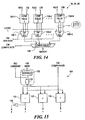
- Figure 14 shows the general structure of the comparison logic blocks 92, 94 and 96.
- Two or more blocks of comparator logic 104-1, ... 104-n are used to perform multiple comparisons in parallel, where each comparison is between a given field of a request and a corresponding field of a criterion memory entry.
- the comparison logic 92 for CMO 86 for example, two comparator logic blocks 104 are employed, one for the Source Address field of the request and one for the Destination Address field of the request.
- the comparison logic 94 for CMI 88 contains comparator logic blocks 104 for Source Address, Destination Address, IP Protocol, Source Port and Destination Port.
- the comparison logic 96 for CM2 90 contains comparator logic blocks 104 for Source Address, Destination Address, IP Protocol, Source Port, Destination Port, Type of Service without mask, Type of Service with mask, and Flags.
- the selectors 106 receive the operators from an operator-type rule memory entry as control inputs. These operators reside within bits 35-12 of the rule memory entry, as described above.
- the respective outputs of the selectors 106 are provided to another selector 108, which selects from among different combinations of the outputs of the selectors 106 based on the configuration bits from the criterion memory entry.
- the configuration selector 108 selects between a SA comparison result and a DA comparison result based on the value of bit 37 of the criterion memory entry.
- the configuration selectors 108 in the other comparison logic blocks 94 and 96 operate similarly.
- the output signal MATCH from the configuration selector 108 indicates whether the data in the request satisfies the criteria from the respective criterion memory 86, 88 or 90.
- the MATCH outputs from the comparison blocks 92, 94 and 96 are ANDed together by an AND gate 10, to provide a single MATCH indication to the addressing and control logic 98 for controlling the classification operation.
- Figure 15 shows the general structure of a comparator logic block 104.
- An EQUAL comparator 110 determines whether two comparands are equal, a LESS THAN comparator 112 determines whether one of the comparands is less than the other comparand, and a GREATER THAN comparator 114 determines whether the one comparand is greater than the other comparand.
- the output from the EQUAL comparator 110 is inverted by an inverter 116 to obtain the NOT EQUAL indication.
- each comparator 110, 112, and 114 are a comparand from the CM 84 (shown as "CM comparand") and a possibly masked comparand from the request (shown as REQ comparand).
- Masking logic is used for those fields having associated masks.
- AND gates 118 implement bit-by-bit masking.
- the multi-bit mask (shown as "CM mask”) may be used directly, as in the case of the Flags Mask, or it may be decoded or expanded by expander logic 120, as in the case of the SA/DA Mask.
- the expander logic 120 generates a 32-bit value having zeroes in a number of trailing bit positions as indicated by the 5-bit encoded mask value, and ones elsewhere.
- the decoded mask is FFFFF800 hexadecimal, which has ones in the leading 21 positions and zeros in the trailing 11 positions. This mask indicates that only the most significant 21 bits of the SA/DA should affect the comparison result.
- PCE packet classification engine
- the CM 84 can be used in a variety of different configurations.
- Each of the three memories CM0 86, CM1 88 and CM2 90 can be used in different modes to realize the different configurations.
- the following truth table presents the different comparisons that can be performed using the different configuration modes of the criteria memories 86, 88 and 90. A "1" indicates that a comparison can be performed using a given configuration mode, and a "0" indicates that the comparison cannot be performed.
- an SA comparison can be performed using any of CM0-0, CM1-0, and CM2-0.
- a FLAGS comparison can be performed using any of CM2-4 through CM2-7.
- the ability to perform a given comparison using any of a variety of configuration modes provides desirable flexibility in organizing CM 84, which in turn enhances efficiency.
- the allocation of criterion memory space is described in some detail below.
- Figure 16 shows the manner in which packet filtering information is managed and utilized in the switch 10 of Figure 1.
- the source of packet filtering information is a network management station (NMS), which is typically located apart from the switch 10 of Figure 1.
- the NMS communicates with a central processor (CP) residing within the switch control 18 of Figure 1 using a network management protocol such as Simple Network Management Protocol (SNMP).
- SNMP Simple Network Management Protocol
- the CP receives the filtering information from the NMS, and is responsible for distributing it to the IOP 26 of each line interface 12. Additionally, the CP maintains the information in non-volatile (NV) storage, so that the switch 10 is able to operate during periods when the NMS may be unavailable.
- NV non-volatile
- the filter information sent from the CP to the IOP 26 includes (1) filters, each of which specifies up to a small number of criteria that can be applied to received packets, (2) bindings, that is, information associating different groups of the filters with different ports and/or circuits in the switch 10, and (3) actions, having associations with the filters, which are to be performed when filter criteria are satisfied.
- the CP retrieves an existing filtering table and binding database from the NV storage and downloads them to the IOP 26 of each line interface 12.
- the NMS adds, deletes or modifies a filter or binding, it issues an SNMP action request to pass the new information to the CP.
- the CP posts the change to each IOP 26.
- the IOP 26 receives the filtering information from the CP and instantiates local copies of the filters, bindings and actions into its memory. The IOP 26 updates these local copies whenever the CP sends new information.
- the IOP 26 programs the FP memory 60 in each forwarding engine 22 of Figure 2 with a table of different actions that can be taken for the various filters.
- the IOP 26 also creates RM entries and CM entries corresponding to the filters and bindings, and programs the RM 82 and CM 84 ( Figure 9) of the PCE 76 ( Figure 5) with these entries. Whenever the IOP 26 receives new filtering information from the CP, RM and CM entries are deleted, added, or changed as necessary.
- the FP 58 is responsible for processing packets with the assistance of the PCE 76. Using the information provided by the IOP 26, the FP 58 maps the port and circuit identities of each received packet into root 0 and root 1 addresses, creates a PCE request using these addresses, and writes the request to the PCE 76 via the request queue 70 ( Figure 5). As mentioned above, the FP 58 generally attempts to operate the PCE 76 in a batch fashion by writing a burst of multiple requests if possible. The PCE processes the requests in the manner described above. The FP 58 polls the PCE 76 to obtain results, which are returned by the PCE 76 in blocks as described above. For each result in which a match is indicated, the PCE match address from the result is used as an index into the action table established by the IOP 26 to ascertain which action to take for the packet. The FP 58 then performs the indicated action.
- IP Internet Protocol
Landscapes
- Engineering & Computer Science (AREA)
- Computer Networks & Wireless Communication (AREA)
- Signal Processing (AREA)
- Data Exchanges In Wide-Area Networks (AREA)
- Small-Scale Networks (AREA)
- Telephonic Communication Services (AREA)
Claims (16)
- Appareil de classification de paquets, caractérisé par :une logique d'interface d'entrée (12) servant à recevoir une demande de classification de paquet comportant des informations d'un paquet traité par un demandeur de classification de paquet ;une mémoire de règles (82) servant à mémoriser des entrées de mémoire de règles, chaque entrée de mémoire de règle contenant un opérateur et un pointeur de mémoire de critères ;une mémoire de critères (84) servant à mémoriser des entrées de mémoire de critères, chaque entrée de mémoire de critères contenant au moins une valeur de comparaison ;une logique d'interface de sortie (12) servant à fournir un résultat de classification de paquet au demandeur de classification de paquet ; et
une logique de commande (82, 84, 92, 94, 96) servant en réponse à la demande de classification de paquet reçue à :(i) recouvrer une entrée de mémoire de règles de la mémoire de règles ;(ii) recouvrer une entrée de mémoire de critères de la mémoire de critères à une position spécifiée par le pointeur de mémoire de critères dans l'entrée de mémoire de règles recouvrée ;(iii) exécuter une opération spécifiée par l'opérateur dans l'entrée de mémoire de règles recouvrée, l'opération étant effectuée sur les informations de paquet de la demande de classification de paquet et la valeur de l'entrée de mémoire de critères recouvrée ; et(iv) générer un résultat de classification de paquet qui reflète le résultat de l'exécution de l'opération. - Appareil de classification de paquets selon la revendication 1, dans lequel :la mémoire de règles sert à mémoriser des entrées de mémoire de règles à la fois d'un premier type et d'un second type, chaque entrée de mémoire de règles du premier type contenant un opérateur et un pointeur de mémoire de critères, et chaque entrée de mémoire de règles du second type contenant un pointeur de mémoire de règles ; etla logique de commande sert en réponse à la demande de classification de paquet reçue à :(i) déterminer si l'entrée de mémoire de règles recouvrée est une entrée du premier type ou une entrée du second type ;(ii) recouvrer l'entrée de mémoire de critères et exécuter l'opération spécifiée si l'entrée de mémoire de règles recouvrée est une entrée du premier type ;(iii) si l'entrée de mémoire de règles recouvrée est une entrée du second type, recouvrer alors une autre entrée de mémoire de règles à une position spécifiée par le pointeur de mémoire de règles contenu dans l'entrée du second type, et répéter les étapes précédentes pour l'entrée de mémoire de règles nouvellement recouvrée ; et(iv) générer un résultat de classification de paquets reflétant les résultats de l'exécution des opérations respectives spécifiées par toutes les entrées du premier type recouvrées.
- Appareil de classification de paquets selon la revendication 1, dans lequel la logique de commande fonctionne en outre pour répéter les étapes (i) à (iii) pour d'autres entrées de mémoire de règles jusqu'à ce qu'une indication de fin soit atteinte.
- Appareil de classification de paquets selon la revendication 3, dans lequel l'indication de fin est un bit FAIT établi dans une entrée de mémoire de règles recouvrée.
- Appareil de classification de paquets selon la revendication 3, dans lequel l'indication de fin est la satisfaction d'une condition spécifiée par l'opérateur dans une entrée de mémoire de règles recouvrée.
- Appareil de classification de paquets selon la revendication 3, dans lequel les autres entrées de mémoire de règles sont recouvrées en sollicitant séquentiellement les positions successives dans la mémoire de règles.
- Appareil de classification de paquets selon la revendication 3, dans lequel les autres entrées de mémoire de règles sont recouvrées en sollicitant des positions spécifiées dans les pointeurs de mémoire de règles contenus dans des entrées de mémoire de règles recouvrées.
- Appareil de classification de paquets selon la revendication 1, dans lequel la logique de commande sert à recouvrer l'entrée de mémoire de règles en se basant sur une adresse de mémoire de règles incluse dans la demande de classification de paquet reçue.
- Appareil de classification de paquets selon la revendication 1, dans lequel l'entrée de mémoire de règles recouvrée par la logique de commande est une première entrée de mémoire de règles, la logique de commande servant à sélectionner la première entrée de mémoire de règles en se basant sur une première adresse de mémoire de règles incluse dans la demande de classification de paquets reçue, et dans lequel la logique de commande sert en outre à sélectionner une seconde entrée de mémoire de règles en se basant sur une seconde adresse de mémoire de règles également incluse dans la demande de classification de paquet reçue, et à répéter les étapes (i) à (iii) pour la seconde entrée de mémoire de règles.
- Appareil de classification de paquets selon la revendication 1, dans lequel l'entrée de mémoire de règles contient un indicateur de REPORT indiquant si l'entrée de mémoire de règles est une première entrée de mémoire de règles formant une règle composée avec une seconde entrée de mémoire de règles, et dans lequel la logique de commande sert à répéter les étapes (i) à (iii) pour la seconde entrée de mémoire de règles et à générer le résultat de classification de paquet à l'étape (iv) de telle sorte que le résultat de classification de paquet reflète les résultats des opérations des deux première et seconde entrées de mémoire de règles.
- Appareil de classification de paquets selon la revendication 1, dans lequel la valeur dans l'entrée de mémoire de critères et les informations dans la demande sont des adresses de réseau.
- Appareil de classification de paquets selon la revendication 11, dans lequel les adresses sont des adresses destinataires.
- Appareil de classification de paquets selon la revendication 1, dans lequel chaque entrée de mémoire de critères contient des informations de configuration indiquant une manière dont l'entrée de mémoire de critères est configurée, et la logique de commande sert à (i) interpréter les informations de configuration de l'entrée de mémoire de critères recouvrée afin de déterminer parmi les champs multiples de l'entrée de mémoire de critères ceux à utiliser dans l'opération ; et (ii) exécuter l'opération en n'utilisant que les champs appropriées de la mémoire de critères et les informations correspondantes de la demande de classification de paquet en fonction de la configuration déterminée.
- Appareil de classification de paquets selon la revendication 1, dans lequel chaque entrée de mémoire de critères contient des informations de configuration indiquant une manière dont l'entrée de mémoire de critères est configurée, et la logique de commande sert à (i) interpréter les informations de configuration de l'entrée de mémoire de critères recouvrée afin de déterminer dans la demande de classification de paquet les informations à utiliser dans l'opération ; et (ii) exécuter l'opération en n'utilisant que les informations appropriées de la demande de classification de paquet et les informations correspondantes dans l'entrée de mémoire de critères en fonction de la configuration déterminée.
- Appareil de classification de paquets selon la revendication 1, dans lequel la mémoire de critères est organisée en divisions principales de telle sorte que chaque entrée de mémoire de critères comporte des champs différents associés respectivement aux différentes divisions principales, chaque champ étant configurable pour contenir différents types de valeurs conformément aux informations de configuration contenues dans l'entrée de mémoire de critères, et dans lequel la logique de commande sert pour chaque division principale à sélectionner des informations de la demande de classification de paquet à utiliser dans l'opération avec le champ respectif de l'entrée de mémoire de critères en fonction des informations de configuration contenues dans l'entrée de mémoire de critères.
- Appareil de classification de paquets selon la revendication 15, dans lequel la mémoire de critères comporte trois divisions principales de telle sorte que chaque entrée de mémoire de critères contienne un premier champ configurable comme adresse source ou comme adresse destinataire, un deuxième champ configurable comme adresse source, comme adresse destinataire, ou comme un ensemble d'informations d'identification de port, et un troisième champ configurable comme adresse source, comme adresse destinataire, comme un ensemble d'informations d'identification de port ou comme un ensemble d'informations de signalisation.
Applications Claiming Priority (2)
| Application Number | Priority Date | Filing Date | Title |
|---|---|---|---|
| US459448 | 1999-12-13 | ||
| US09/459,448 US6587463B1 (en) | 1999-12-13 | 1999-12-13 | Packet classification engine |
Publications (3)
| Publication Number | Publication Date |
|---|---|
| EP1128609A2 EP1128609A2 (fr) | 2001-08-29 |
| EP1128609A3 EP1128609A3 (fr) | 2004-03-24 |
| EP1128609B1 true EP1128609B1 (fr) | 2006-03-15 |
Family
ID=23824816
Family Applications (1)
| Application Number | Title | Priority Date | Filing Date |
|---|---|---|---|
| EP00310753A Expired - Lifetime EP1128609B1 (fr) | 1999-12-13 | 2000-12-04 | Automate de classification de paquets |
Country Status (5)
| Country | Link |
|---|---|
| US (1) | US6587463B1 (fr) |
| EP (1) | EP1128609B1 (fr) |
| JP (1) | JP3734704B2 (fr) |
| CA (1) | CA2326939C (fr) |
| DE (1) | DE60026676T2 (fr) |
Families Citing this family (36)
| Publication number | Priority date | Publication date | Assignee | Title |
|---|---|---|---|---|
| US7286532B1 (en) * | 2001-02-22 | 2007-10-23 | Cisco Technology, Inc. | High performance interface logic architecture of an intermediate network node |
| US6973072B1 (en) * | 2001-02-22 | 2005-12-06 | Cisco Technology, Inc. | High performance protocol for an interconnect system of an intermediate network node |
| US7230917B1 (en) * | 2001-02-22 | 2007-06-12 | Cisco Technology, Inc. | Apparatus and technique for conveying per-channel flow control information to a forwarding engine of an intermediate network node |
| US6940854B1 (en) * | 2001-03-23 | 2005-09-06 | Advanced Micro Devices, Inc. | Systems and methods for determining priority based on previous priority determinations |
| US7366194B2 (en) * | 2001-04-18 | 2008-04-29 | Brocade Communications Systems, Inc. | Fibre channel zoning by logical unit number in hardware |
| US7167472B2 (en) * | 2001-04-18 | 2007-01-23 | Brocade Communications Systems, Inc. | Fibre channel zoning by device name in hardware |
| US7327760B1 (en) * | 2001-05-08 | 2008-02-05 | Cortina Systems, Inc. | Multi-service segmentation and reassembly device operable with either a cell-based or a packet-based switch fabric |
| US7389360B1 (en) | 2001-11-05 | 2008-06-17 | Juniper Networks, Inc. | Context switched route lookup key engine |
| US7813346B1 (en) | 2001-11-21 | 2010-10-12 | Juniper Networks, Inc. | Filter-based forwarding in a network |
| US7043544B2 (en) * | 2001-12-21 | 2006-05-09 | Agere Systems Inc. | Processor with multiple-pass non-sequential packet classification feature |
| US7209482B1 (en) | 2001-12-21 | 2007-04-24 | Juniper Networks, Inc. | Reorder engine with error recovery |
| US7423975B2 (en) * | 2002-03-05 | 2008-09-09 | Broadcom Corporation | Method, apparatus and computer program product for performing data packet classification |
| US7684400B2 (en) * | 2002-08-08 | 2010-03-23 | Intel Corporation | Logarithmic time range-based multifield-correlation packet classification |
| US7724740B1 (en) * | 2002-08-27 | 2010-05-25 | 3Com Corporation | Computer system and network interface supporting class of service queues |
| US7554980B1 (en) * | 2002-10-18 | 2009-06-30 | Alcatel Lucent | Packet classification using relevance scoring |
| US8040886B2 (en) * | 2003-04-08 | 2011-10-18 | Cisco Technology, Inc. | Programmable packet classification system using an array of uniform content-addressable memories |
| US7352740B2 (en) * | 2003-04-29 | 2008-04-01 | Brocade Communciations Systems, Inc. | Extent-based fibre channel zoning in hardware |
| US7260840B2 (en) * | 2003-06-06 | 2007-08-21 | Microsoft Corporation | Multi-layer based method for implementing network firewalls |
| US8788823B1 (en) * | 2003-09-03 | 2014-07-22 | Cisco Technology, Inc. | System and method for filtering network traffic |
| US7430203B2 (en) * | 2004-01-29 | 2008-09-30 | Brocade Communications Systems, Inc. | Fibre channel zoning hardware for directing a data packet to an external processing device |
| CN100347992C (zh) * | 2004-07-09 | 2007-11-07 | 清华大学 | 实现线速对数据流按规则库近似匹配的可配置的硬件结构 |
| US7492763B1 (en) * | 2004-07-16 | 2009-02-17 | Applied Micro Circuits Corporation | User-specified key creation from attributes independent of encapsulation type |
| US7340570B2 (en) * | 2004-08-18 | 2008-03-04 | Intel Corporation | Engine for comparing a key with rules having high and low values defining a range |
| US7630318B2 (en) * | 2004-12-15 | 2009-12-08 | Agilent Technologies, Inc. | Filtering wireless network packets |
| US8631483B2 (en) * | 2005-06-14 | 2014-01-14 | Texas Instruments Incorporated | Packet processors and packet filter processes, circuits, devices, and systems |
| JP2007243300A (ja) * | 2006-03-06 | 2007-09-20 | Fujitsu Ltd | 帯域制御プログラム、帯域制御装置、帯域制御方法 |
| US20090052443A1 (en) * | 2007-08-23 | 2009-02-26 | Santosh Kolenchery | Method and apparatus for managing dynamic filters for nested traffic flows |
| US20090271857A1 (en) * | 2008-04-25 | 2009-10-29 | Jia Wang | Method and apparatus for filtering packets using an approximate packet classification |
| US7957273B2 (en) * | 2008-06-06 | 2011-06-07 | Redpine Signals, Inc. | Packet re-transmission controller for block acknowledgement in a communications system |
| US9106539B2 (en) * | 2009-03-26 | 2015-08-11 | At&T Intellectual Property I, L.P. | User-controlled network configuration for handling multiple classes of service |
| DE102010020446B4 (de) | 2010-05-12 | 2012-12-06 | Wago Verwaltungsgesellschaft Mbh | Automatisierungsgerät und Verfahren zur beschleunigten Verarbeitung von selektierten Prozessdaten |
| TWI540431B (zh) * | 2014-09-04 | 2016-07-01 | 晨星半導體股份有限公司 | 電子裝置及其管理方法 |
| US10326817B2 (en) * | 2016-12-20 | 2019-06-18 | Cisco Technology, Inc. | System and method for quality-aware recording in large scale collaborate clouds |
| JP7225729B2 (ja) * | 2018-11-21 | 2023-02-21 | 株式会社デンソー | 中継装置及び中継方法 |
| EP4113951B1 (fr) * | 2021-06-29 | 2025-01-01 | Renesas Electronics Corporation | Traitement de données de cadre |
| US20230319168A1 (en) * | 2022-04-01 | 2023-10-05 | Nxp B.V. | Hardware ethernet header verification |
Family Cites Families (4)
| Publication number | Priority date | Publication date | Assignee | Title |
|---|---|---|---|---|
| JP3369204B2 (ja) * | 1991-10-25 | 2003-01-20 | 株式会社東芝 | プログラマブルコントローラ |
| US5818838A (en) * | 1995-10-12 | 1998-10-06 | 3Com Corporation | Method and apparatus for transparent intermediate system based filtering on a LAN of multicast packets |
| US6081522A (en) * | 1997-06-30 | 2000-06-27 | Sun Microsystems, Inc. | System and method for a multi-layer network element |
| US6041053A (en) * | 1997-09-18 | 2000-03-21 | Microsfot Corporation | Technique for efficiently classifying packets using a trie-indexed hierarchy forest that accommodates wildcards |
-
1999
- 1999-12-13 US US09/459,448 patent/US6587463B1/en not_active Expired - Fee Related
-
2000
- 2000-11-28 CA CA002326939A patent/CA2326939C/fr not_active Expired - Fee Related
- 2000-12-04 EP EP00310753A patent/EP1128609B1/fr not_active Expired - Lifetime
- 2000-12-04 DE DE60026676T patent/DE60026676T2/de not_active Expired - Fee Related
- 2000-12-13 JP JP2000378432A patent/JP3734704B2/ja not_active Expired - Fee Related
Also Published As
| Publication number | Publication date |
|---|---|
| DE60026676T2 (de) | 2006-11-09 |
| US6587463B1 (en) | 2003-07-01 |
| JP3734704B2 (ja) | 2006-01-11 |
| CA2326939A1 (fr) | 2001-06-13 |
| EP1128609A2 (fr) | 2001-08-29 |
| EP1128609A3 (fr) | 2004-03-24 |
| JP2001223749A (ja) | 2001-08-17 |
| DE60026676D1 (de) | 2006-05-11 |
| CA2326939C (fr) | 2007-01-09 |
Similar Documents
| Publication | Publication Date | Title |
|---|---|---|
| EP1128609B1 (fr) | Automate de classification de paquets | |
| EP1109363B1 (fr) | Dispositif d'achéminement | |
| US8254397B2 (en) | Interconnecting network processors with heterogeneous fabrics | |
| US7647472B2 (en) | High speed and high throughput digital communications processor with efficient cooperation between programmable processing components | |
| US5251207A (en) | Combined terminal adapter for SMDS and frame relay high speed data services | |
| US6275861B1 (en) | Method and apparatus to identify flows in data systems | |
| US7447204B2 (en) | Method and device for the classification and redirection of data packets in a heterogeneous network | |
| US7016352B1 (en) | Address modification within a switching device in a packet-switched network | |
| US6687247B1 (en) | Architecture for high speed class of service enabled linecard | |
| US5487064A (en) | Network layer packet structure | |
| US7466700B2 (en) | LUN based hard zoning in fibre channel switches | |
| US20050171937A1 (en) | Memory efficient hashing algorithm | |
| US20050018673A1 (en) | Method and system for using extended fabric features with fibre channel switch elements | |
| EP1005746B1 (fr) | Procede et dispositif pour la consultation de reacheminement de paquets par le reseau avec nombre reduit d'acces memoire | |
| US6208650B1 (en) | Circuit for performing high-speed, low latency frame relay switching with support for fragmentation and reassembly and channel multiplexing | |
| CA2326928C (fr) | Moteur de recherche de trajet | |
| JP2001292155A (ja) | データ通信スイッチ用の優先順位リマッピング | |
| JP2001285333A (ja) | データ通信スイッチのための選択可能な優先順位付け | |
| WO1999059078A9 (fr) | Processeur de communications numeriques | |
| EP1232612B1 (fr) | Mecanisme de recherche dans une table pour resolution d'adresse dans reseau a commutation par paquets | |
| EP1195954B1 (fr) | Table de recherche basée sur une tuple pour une noeud à commutation de paquet | |
| EP1290831B1 (fr) | Processeur de paquets de communication pourvu d'un moteur de recherche permettant de recuperer les informations de contexte pour un processeur central | |
| US20040143592A1 (en) | Method for processing redundant packets in computer network equipment |
Legal Events
| Date | Code | Title | Description |
|---|---|---|---|
| PUAI | Public reference made under article 153(3) epc to a published international application that has entered the european phase |
Free format text: ORIGINAL CODE: 0009012 |
|
| AK | Designated contracting states |
Kind code of ref document: A2 Designated state(s): AT BE CH CY DE DK ES FI FR GB GR IE IT LI LU MC NL PT SE TR |
|
| AX | Request for extension of the european patent |
Free format text: AL;LT;LV;MK;RO;SI |
|
| PUAL | Search report despatched |
Free format text: ORIGINAL CODE: 0009013 |
|
| AK | Designated contracting states |
Kind code of ref document: A3 Designated state(s): AT BE CH CY DE DK ES FI FR GB GR IE IT LI LU MC NL PT SE TR |
|
| AX | Request for extension of the european patent |
Extension state: AL LT LV MK RO SI |
|
| 17P | Request for examination filed |
Effective date: 20040911 |
|
| 17Q | First examination report despatched |
Effective date: 20041007 |
|
| AKX | Designation fees paid |
Designated state(s): DE GB |
|
| GRAP | Despatch of communication of intention to grant a patent |
Free format text: ORIGINAL CODE: EPIDOSNIGR1 |
|
| GRAS | Grant fee paid |
Free format text: ORIGINAL CODE: EPIDOSNIGR3 |
|
| GRAA | (expected) grant |
Free format text: ORIGINAL CODE: 0009210 |
|
| AK | Designated contracting states |
Kind code of ref document: B1 Designated state(s): DE GB |
|
| REG | Reference to a national code |
Ref country code: GB Ref legal event code: FG4D |
|
| REF | Corresponds to: |
Ref document number: 60026676 Country of ref document: DE Date of ref document: 20060511 Kind code of ref document: P |
|
| PLBE | No opposition filed within time limit |
Free format text: ORIGINAL CODE: 0009261 |
|
| STAA | Information on the status of an ep patent application or granted ep patent |
Free format text: STATUS: NO OPPOSITION FILED WITHIN TIME LIMIT |
|
| 26N | No opposition filed |
Effective date: 20061218 |
|
| PGFP | Annual fee paid to national office [announced via postgrant information from national office to epo] |
Ref country code: GB Payment date: 20071218 Year of fee payment: 8 |
|
| PGFP | Annual fee paid to national office [announced via postgrant information from national office to epo] |
Ref country code: DE Payment date: 20071221 Year of fee payment: 8 |
|
| GBPC | Gb: european patent ceased through non-payment of renewal fee |
Effective date: 20081204 |
|
| PG25 | Lapsed in a contracting state [announced via postgrant information from national office to epo] |
Ref country code: DE Free format text: LAPSE BECAUSE OF NON-PAYMENT OF DUE FEES Effective date: 20090701 |
|
| PG25 | Lapsed in a contracting state [announced via postgrant information from national office to epo] |
Ref country code: GB Free format text: LAPSE BECAUSE OF NON-PAYMENT OF DUE FEES Effective date: 20081204 |