EP1128623A1 - Verfahren zur Minimizierung der Sendeleistung von nicht-aktiven ATM Zellen in einem XDSL System mit trelliskodierter Modulation - Google Patents
Verfahren zur Minimizierung der Sendeleistung von nicht-aktiven ATM Zellen in einem XDSL System mit trelliskodierter Modulation Download PDFInfo
- Publication number
- EP1128623A1 EP1128623A1 EP00400505A EP00400505A EP1128623A1 EP 1128623 A1 EP1128623 A1 EP 1128623A1 EP 00400505 A EP00400505 A EP 00400505A EP 00400505 A EP00400505 A EP 00400505A EP 1128623 A1 EP1128623 A1 EP 1128623A1
- Authority
- EP
- European Patent Office
- Prior art keywords
- data
- constellation points
- modulator
- shifting
- null data
- Prior art date
- Legal status (The legal status is an assumption and is not a legal conclusion. Google has not performed a legal analysis and makes no representation as to the accuracy of the status listed.)
- Withdrawn
Links
Images

Classifications
-
- H—ELECTRICITY
- H04—ELECTRIC COMMUNICATION TECHNIQUE
- H04M—TELEPHONIC COMMUNICATION
- H04M11/00—Telephonic communication systems specially adapted for combination with other electrical systems
- H04M11/06—Simultaneous speech and data transmission, e.g. telegraphic transmission over the same conductors
- H04M11/062—Simultaneous speech and data transmission, e.g. telegraphic transmission over the same conductors using different frequency bands for speech and other data
-
- H—ELECTRICITY
- H04—ELECTRIC COMMUNICATION TECHNIQUE
- H04L—TRANSMISSION OF DIGITAL INFORMATION, e.g. TELEGRAPHIC COMMUNICATION
- H04L1/00—Arrangements for detecting or preventing errors in the information received
- H04L1/004—Arrangements for detecting or preventing errors in the information received by using forward error control
- H04L1/0056—Systems characterized by the type of code used
- H04L1/0059—Convolutional codes
- H04L1/006—Trellis-coded modulation
-
- H—ELECTRICITY
- H04—ELECTRIC COMMUNICATION TECHNIQUE
- H04L—TRANSMISSION OF DIGITAL INFORMATION, e.g. TELEGRAPHIC COMMUNICATION
- H04L27/00—Modulated-carrier systems
- H04L27/26—Systems using multi-frequency codes
- H04L27/2601—Multicarrier modulation systems
- H04L27/2626—Arrangements specific to the transmitter only
- H04L27/2627—Modulators
-
- H—ELECTRICITY
- H04—ELECTRIC COMMUNICATION TECHNIQUE
- H04L—TRANSMISSION OF DIGITAL INFORMATION, e.g. TELEGRAPHIC COMMUNICATION
- H04L27/00—Modulated-carrier systems
- H04L27/26—Systems using multi-frequency codes
- H04L27/2601—Multicarrier modulation systems
- H04L27/2647—Arrangements specific to the receiver only
- H04L27/2649—Demodulators
-
- H—ELECTRICITY
- H04—ELECTRIC COMMUNICATION TECHNIQUE
- H04L—TRANSMISSION OF DIGITAL INFORMATION, e.g. TELEGRAPHIC COMMUNICATION
- H04L12/00—Data switching networks
- H04L12/54—Store-and-forward switching systems
- H04L12/56—Packet switching systems
- H04L12/5601—Transfer mode dependent, e.g. ATM
- H04L2012/5603—Access techniques
- H04L2012/5609—Topology
- H04L2012/561—Star, e.g. cross-connect, concentrator, subscriber group equipment, remote electronics
-
- Y—GENERAL TAGGING OF NEW TECHNOLOGICAL DEVELOPMENTS; GENERAL TAGGING OF CROSS-SECTIONAL TECHNOLOGIES SPANNING OVER SEVERAL SECTIONS OF THE IPC; TECHNICAL SUBJECTS COVERED BY FORMER USPC CROSS-REFERENCE ART COLLECTIONS [XRACs] AND DIGESTS
- Y02—TECHNOLOGIES OR APPLICATIONS FOR MITIGATION OR ADAPTATION AGAINST CLIMATE CHANGE
- Y02D—CLIMATE CHANGE MITIGATION TECHNOLOGIES IN INFORMATION AND COMMUNICATION TECHNOLOGIES [ICT], I.E. INFORMATION AND COMMUNICATION TECHNOLOGIES AIMING AT THE REDUCTION OF THEIR OWN ENERGY USE
- Y02D30/00—Reducing energy consumption in communication networks
- Y02D30/50—Reducing energy consumption in communication networks in wire-line communication networks, e.g. low power modes or reduced link rate
Definitions
- the present invention relates to a method to transfer data from a digital data modulator device to a digital data demodulator device over a digital subscriber line, said method includes, in said modulator device, the steps of modulating incoming groups of data bits into data symbols according to the trellis code modulation technique and of mapping said data symbols on carriers associated to constellation points of a constellation scheme and, in said demodulator device, the steps of de-mapping received carriers into data symbols and of de-modulating said data symbols into groups of data bits according to the trellis code de-modulation technique.
- Such a method to transfer digital data is generally known in the art and may for instance be derived from the "DRAFT STANDARD” of ANSI “T1.413-1998 Issue 2” entitled “Network and Customer Installation Interfaces - Asymmetric Digital Subscriber Line (ADSL) Metallic Interface” of the "COMMITTEE T1 - TELECOMMUNICATIONS - Working Group T1E1.4 T1E1.4/98-007R5, Plano, TX; 30 November - 4 December 1998".
- the invention more particularly relates to such a method used in an ADSL [Asymmetric Digital Subscriber Line] modem or any higher version thereof such as a VDSL [Very High Speed Digital Subscriber Line] modem which transfers ATM [Asynchronous Transfer Mode] cells over a ADSL/VDSL network segment as mentioned in the "Nortel standard contribution” entitled “On the ATM TC for VDSL” from the author L. D. Humphrey. This standard contribution with reference “ TD44 Antwerp” was presented on the meeting of 20-24'th April 1998 in Antwerp of ETSI's Sub-Technical Committee TM6.
- this modem replaces the idle ATM cells with null ATM cells, i.e. cells whose header and payload sections are completely filled with zero bytes, whilst these of the idle ATM cells not always are.
- the modem further associates with null data symbols corresponding to the null ATM cells the origin point of a constellation diagram used to modulate carrier(s). In this way, transmitted power is reduced to a minimum during transfer of idle ATM cells and FEXT [Far End CrossTalk] is significantly reduced.
- Frequency EQualizer [FEQ] of the demodulator is hampered if a sequence of powerless data symbols arrives there, as a consequence of which the known modulation technique is not suitable for use in modems equipped with an adaptive FEQ whose taps are adjusted on the basis of information in the received data symbols, such as a DMT [Discrete Multi Tone] modem used in an ADSL [Asymmetric Digital Subscriber Line] or in a VDSL [Very High Speed Digital Subscriber Line] environment.
- DMT Discrete Multi Tone
- ADSL Asymmetric Digital Subscriber Line
- VDSL Very High Speed Digital Subscriber Line
- the correction bit(s) inserted thereby leads to create data symbols that are not always null, even for null ATM cells.
- Carriers associated to data symbols derived from null ATM cells can however be represented by four constellation points located in the first quadrant of the constellation diagram. Consequently, the transmission power may be relatively high during the transmission of idle ATM cells on the digital subscriber or telephone line.
- An object of the present invention is to provide a method of the above known type but wherein, during the transfer of idle data over the digital subscriber line, the power consumption is minimized.
- this object is achieved due to the fact that said method further includes, in said modulator device, the step of detecting incoming idle data, and in case idle data are detected, the step of generating null data cells derived from said idle data, and, after said steps of modulating and of mapping, the step of shifting constellation points corresponding to said null data cells towards constellation points having a relatively lower power, and in said demodulator device, the step of detecting received null data, and in case null data are detected, the step of de-shifting constellation points having the relatively lowest power towards constellation points corresponding to null data cells, prior to said steps of de-mapping and of de-modulating.
- the QAM [Quadrature Amplitude Modulation] constellation points having the lowest power are the four points located each in a distinct quadrants and nearest to the origin of the constellation diagram. In this way, by associating a low power constellation point with idle data, the transmitted power is minimized during idle data transmission but no zero power points are transmitted so that it is no longer necessary to sum eight successive carriers to enable detection as mentioned above.
- the training and tracking of the frequency equalizer in the demodulator device is thereby simplified.
- said method further includes in said modulator device the step of randomly rotating constellation points corresponding to said null data cells amongst each other, and in said demodulator device the step of randomly de-rotating constellation points to obtain constellation points corresponding to null data cells.
- null data will always be mapped on the same position in the constellation diagram.
- the FEQ training and tracking is improved without increasing the transmitted power.
- all idle data cells are represented by in-phase carriers, which would otherwise result in a high crest factor in multi-carrier systems.
- the Peak-to-Average Ratio [PAR] value is reduced and the FEQ updating is no longer disturbed by a constant interferer.
- the method of the present invention is further characterized in that said constellation points are randomly rotated and randomly de-rotated over an integer multiple of 90 degrees.
- the constellation points may either be shifted and then rotated or first be rotated and then shifted. In the first case, the constellation points are rotated around the origin of the constellation diagram.
- the present invention also relates to a digital data modulator device and to a digital data demodulator device adapted to use the above-described method.
- the digital data modulator device of the present invention comprises a trellis code modulator adapted to modulate incoming groups of data bits into data symbols according to the trellis code modulation technique, and a data encoder adapted to map said data symbols on carriers associated to constellation points of a constellation scheme.
- the modulator device further comprises detection means adapted to detect incoming idle data, null data cell generation means adapted to generate null data cells as derived from said idle data and coupled to an input of said trellis code modulator, constellation points shifting means coupled to an output of said data encoder and adapted to move constellation points corresponding to said null data cells towards constellation points having a relatively lower power, and control means adapted to control the operation of said null data cell generation means and of said shifting means upon detection of idle data by said detection means.
- the digital data modulator device is characterized in that it further comprises constellation points rotation means adapted to rotate amongst each other constellation points corresponding to said null data cells, the operation of said rotation means being also controlled by said control means.
- the digital data demodulator device of the present invention comprises a data decoder adapted to translate received carriers into data symbols, and a trellis code de-modulator adapted to demodulate said data symbols into groups of data bits according to the trellis code de-modulation technique.
- the demodulator device further comprises detection means adapted to detect received null data, constellation points de-shifting means adapted to move constellation points having the relatively lowest power towards constellation points corresponding to null data cells, and control means adapted to control the operation of said shifting means upon detection of received null data by said detection means, said constellation points de-shifting means being coupled between an input of said demodulator device and an input of said data decoder.
- the digital data demodulator device is characterized in that it further comprises constellation points de-rotation means adapted to rotate amongst each other constellation points corresponding to null data cells, the operation of said rotation means being also controlled by said control means.
- the term 'coupled' should not be interpreted as being limitative to direct connections only.
- the scope of the expression 'a device A coupled to a device B' should not be limited to devices or systems wherein an output of device A is directly connected to an input of device B. It means that there exists a path between an output of A and an input of B which may be a path including other devices or means.
- a digital data modulator device MOD is coupled via a digital subscriber line TL to a digital data demodulator device DMOD.
- the telephone line TL may support one-way communication, i.e. data traffic from the modulator MOD to the demodulator DMOD, or it may be a bi-directional link allowing communication in both directions.
- the modulator MOD and demodulator DMOD form part of two communicating modems which each include the functionality of both the modulator MOD and the demodulator DMOD shown. This is for instance so in an ADSL [Asymmetric Digital Subscriber Line] or in a VDSL [Very High Speed Digital Subscriber Line] system.
- the modulator MOD has an input terminal MIN at which ATM [Asynchronous Transfer Mode] cells are received and to which is connected a detection circuit MDET for detecting incoming idle or unused ATM cells.
- the modulator MOD also comprises a null data cell generator NUL, a trellis code modulator TCM, a data encoder or mapper MMAP, a constellation points rotation circuit MRAN, a constellation points shifting circuit MTRN and an inverse fast Fourier transformer IFFT cascade connected between the input MIN and an output of MOD connected to the digital subscriber line or telephone line TL.
- the modulator MOD further comprises a control circuit MCTR coupled to an output of the detection circuit MDET and adapted to control the operation of the null data cell generator NUL, the rotation circuit MRAN and the shifting circuit MTRN upon detection of idle ATM cells by MDET.
- the demodulator DMOD has an input connected to the telephone line TL and an output DOUT at which ATM cells are provided.
- the demodulator DMOD comprises, between its input and output DOUT, the cascade connection of a fast Fourier transformer FFT, a constellation points de-shifting circuit DTRN, a constellation points de-rotation circuit DRAN, a data decoder or de-mapper DMAP and a trellis code de-modulator TCD.
- the demodulator DMOD further comprises a detection circuit DDET coupled between the fast Fourier transformer FFT and the de-shifting circuit DTRN and adapted to detect null data received from the telephone line TL.
- An output of the detection circuit DDET is connected to a control circuit DCTR adapted to control the operation of the de-shifting circuit DTRN and the de-rotation circuit DRAN.
- the modulator MOD is a DMT [Discrete Multi Tone] modulator
- the demodulator DMOD is a DMT demodulator
- both are used in a ADSL or VDSL system.
- a system including the modulator MOD and the demodulator DMOD is a multi-carrier system wherein the incoming bits of data are arranged in groups from which are derived data symbols that are modulated on different carriers in accordance with different constellation schemes.
- the amount of bits in each group and thus in each data symbol modulated on a carrier will depend on the SNR [Signal-to-Noise ratio] measured on the telephone line TL at the frequency of that carrier.
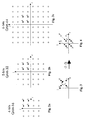
- Each data symbol corresponds to a constellation point in a constellation diagram. Possible constellation points for different carriers corresponding to 4-bits, 5-bits and 6-bits data symbols are represented by dots in the Figs. 2a, 2b and 2c respectively.
- the QAM [Quadrature Amplitude Modulation] is the most used modulation scheme.
- a 4-bits data symbol leads for instance to a QAM-16 modulation scheme, a 5-bits data symbol to QAM-32 and a 6-bits data symbol to QAM-64.
- a n-bits data symbol leads to a QAM-2 n modulation scheme, where 2 n indicates the number of possible constellation points that may represent a data symbol.
- a constellation diagram has real horizontal axis r and an imaginary vertical axis i, and the constellation points are equally distributed in the four quadrants around these axis. It is to be noted that the distance between the points forming a constellation diagram decreases when the number of bits in the constellation increases. Also the transmission power corresponding to points located near to the origin of the diagram is relatively lower than the transmission power of points located further away from this origin. It is also to be noted that the constellation point 0 located near to the origin has a binary value 0000, 00000 and 000000 at the Figs 2a, 2b and 2c respectively, the coordinates of this point 0 is +1 +j.
- ATM cells arrive that have to be transferred over the ADSL or VDSL network segment or telephone line TL between the modulator MOD and demodulator DMOD.
- the detection circuit MDET controls accordingly the control circuit MCTR to deactivate the operation of the null data cell generator NUL, the rotation circuit MRAN and the shifting circuit MTRN. These circuits are then seen as transparent for the non-idle incoming ATM cells.
- the incoming stream of data is arranged in groups of data bits as explained above and these groups are applied to the trellis code modulator TCM that will perform a trellis code modulation thereon.
- the n + m -bits data symbols are applied to the data encoder or mapper MMAP adapted to "map" these data symbols into points of a constellation diagram.
- the mapper MMAP allocates to each carrier of a DMT symbol of the multi-carrier system a data symbol.
- the phase and amplitude of the carriers are modulated by the mapper MMAP in accordance with the constellation scheme in order to associate with each data symbol a constellation point in the constellation diagram.
- the set of carriers constituting one DMT symbol is transformed from the frequency domain to the time domain by the inverse fast Fourier transformer IFFT.
- the time domain DMT symbol is then transferred over the telephone line TL to the demodulator DMOD.
- the fast Fourier transformer FFT transforms the time domain DMT symbol back into a frequency domain DMT symbol.
- the output of fast Fourier transformer FFT is coupled to a Frequency EQualizer FEQ used to compensate for the frequency dependent distortion due to the transmission.
- the non-idle ATM cells received in the demodulator DMOD are detected by the detection circuit DDET which controls accordingly the control circuit DCTR to deactivate the operation of the de-shifting circuit DTRN and the de-rotation circuit DRAN. These circuits are then seen as transparent for the non-idle incoming cells.
- the de-mapper DMAP uses the same constellation schemes as the mapper MMAP in the modulator MOD and extracts from the constellation points of each carrier the data symbol modulated thereon.
- the trellis code de-modulator TCD transforms the data symbol received from the de-mapper DMAP into a group of n data bits by performing an operation opposite to that explained above for the trellis code modulator TCM.
- the detection circuit MDET recognizes these idle ATM cells and controls the control circuit MCTR to activate the operation of the null data cell generator NUL, the rotation circuit MRAN and the shifting circuit MTRN.
- the null data cell generator NUL replaces the incoming idle ATM cells with null data cells, i.e. cells whose header and payload sections are completely filled with zero bytes, whilst these of the idle or unused ATM cells not always are.
- This stream of zero bits is then subdivided into groups of n-bits according to the above described QAM modulation scheme.
- Each group of n-bits is then applied to the trellis code modulator TCM that creates a corresponding data symbol.
- the data symbols are applied to the mapper MMAP that modulates them on the different carriers in accordance with the respective constellation schemes.
- the data symbols corresponding to groups of zero bits modulated according to the trellis code modulation technique by the trellis code modulator TCM are located in the first (upper right) quadrant of the constellation diagram, whatever the QAM modulation scheme used.
- the four possible data symbols representing modulated null data cells are represented by the black dots 0, 1, 2 and 3 in the 4-bits, 5-bits and 6-bits constellation diagrams of the Figs. 2a, 2b and 2c respectively. These four points distinguish only by their 2 Least Significant Bits [LSB]. Amongst these four points, the constellation point with the lowest transmission power is the point 0 with coordinate +1 +j, on the r-axis and the i-axis respectively.
- an object of the invention is to reduce to a minimum the transmission power of idle cells, the idea is to shift the four points 0, 1, 2 and 3 from the first quadrant towards four points distributed around the origin of the constellation diagram, with one point in each quadrant. This operation is performed by the constellation points shifting circuit MTRN as shown at Fig. 4.
- the Frequency EQualizer (FEQ) of any ADSL or VDSL DMT receiver or demodulator has to be trained and, in case of a multi-carrier ADSL/VDSL system, clipping due to a high crest factor may occur.
- the present invention adds to solve also this problem. Indeed, in order to simplify the training or update operation of the FEQ of the demodulator, the four points 0, 1, 2 and 3 are also randomly rotated over an integer multiple of 90 degrees. This operation is realized by the constellation points rotation circuit MRAN and results for instance in the points 0', 1', 2' and 3' as shown at Fig. 3. It is to be noted that rotating the constellation points 0, 1, 2 and 3 amongst each other consists in changing their 2 LSB's.
- the rotation also reduces the Peak-to-Average Ratio [PAR] of the transmission signal. Without rotating the data symbols, they should always be mapped on the same constellation point. By rotating them, the effect of constant interference on the FEQ is eliminated.
- the swap between normal and rotated constellation points may be performed after each symbol.
- constellation points shifting circuit MTRN moves the points 0', 1', 2' and 3' to the points 0", 1", 2" and 3", as mentioned above.
- This shifting is shown at Fig. 4 and is performed by adding the value -2-2j to each of the points 0', 1', 2' and 3' of the constellation diagram.
- the inverse fast Fourier transformer IFFT then again transforms the modulated carriers constituting one DMT symbol into a time domain DMT symbol that is transferred over the telephone line TL towards the demodulator DMOD.
- modulator MOD shown at Fig. 1 represents only a preferred embodiment of the invention.
- the following order of the circuits MRAN and MTRN may for instance be inverted without affecting the object of the invention.
- the fast Fourier transformer FFT regenerates the frequency domain DMT symbols from the time domain DMT symbols.
- the null data received in the demodulator DMOD are detected by the detection circuit DDET which controls accordingly the control circuit DCTR to activate the operation of the de-shifting circuit DTRN and the de-rotation circuit DRAN.
- the constellation points de-shifting circuit DTRN moves back the constellation points 0", 1", 2" and 3" towards the points 0', 1', 2' and 3' by adding thereto the value -2 -2j.
- the constellation points are then back in the first quadrant of the constellation diagram as at the output of the constellation points rotation circuit MRAN of the modulator MOD.
- the constellation points de-rotation circuit DRAN returns the randomly rotated points onto their former position by rotating these points by a same multiple of 90 degrees as done by the constellation points rotation circuit MRAN but in the opposite direction.
- the operation only affects the 2 LSB's of the data symbols.
- the data decoder or de-mapper DMAP operates according to the same constellation scheme as the mapper MMAP of the modulator MOD to extract a data symbol from each carrier received from the de-rotation circuit DRAN.
- the trellis code de-modulator TCD performs the same operation as explained above with respect to non-idle cells.
- the data symbols are transformed in groups of data bits, corresponding to null data cells in this case.
- idle ATM cells are provided at the output DOUT of the demodulator DMOD.
- a first remark is that, although the multi-carrier signal in the above described embodiment is transported over a telephone line TL, the applicability of the present invention is not restricted by the transmission medium via which the signal is transported.
- transmission over any kind of connection between the modulator MOD and demodulator DMOD e.g. a cable connection, a satellite connection, a radio link through the air, and so on, may be improved according to the present invention.
- the invention also is not only related to ADSL [Asymmetric Digital Subscriber Line] or similar systems wherein DMT [Discrete Multi Tone] modulation is used.
- ADSL Asymmetric Digital Subscriber Line
- DMT Discrete Multi Tone modulation
- the modulator MOD and the demodulator DMOD may also include other functional blocks not shown in the figures.
- a known "Reed-Solomon" or other CRC error correction circuit may be used to improve the quality of the transmission and/or a scrambler may add a random sequence of bits to the bits of the non-idle incoming ATM cells to obtain a good statistic of the transmitted signal.
- a scrambler may add a random sequence of bits to the bits of the non-idle incoming ATM cells to obtain a good statistic of the transmitted signal.
- Such additional circuits will however not affect the principle of operation of the method according to the invention.
Landscapes
- Engineering & Computer Science (AREA)
- Computer Networks & Wireless Communication (AREA)
- Signal Processing (AREA)
- Digital Transmission Methods That Use Modulated Carrier Waves (AREA)
Priority Applications (5)
| Application Number | Priority Date | Filing Date | Title |
|---|---|---|---|
| EP00400505A EP1128623A1 (de) | 2000-02-24 | 2000-02-24 | Verfahren zur Minimizierung der Sendeleistung von nicht-aktiven ATM Zellen in einem XDSL System mit trelliskodierter Modulation |
| IL14117401A IL141174A0 (en) | 2000-02-24 | 2001-01-30 | Method to transfer data |
| JP2001029392A JP2001352356A (ja) | 2000-02-24 | 2001-02-06 | ディジタル加入者回線を介してトレリスコード変調ディジタルデータを転送する方法、および関連する変調器装置および復調器装置 |
| US09/785,494 US6819719B2 (en) | 2000-02-24 | 2001-02-20 | Method to transfer trellis code modulated digital data over a digital subscriber line, and related modulator and demodulator devices |
| SG200101040A SG100622A1 (en) | 2000-02-24 | 2001-02-22 | Method to transfer trellis code modulated digital data over a digital subscriber line, and related modulator and demodulator devices |
Applications Claiming Priority (1)
| Application Number | Priority Date | Filing Date | Title |
|---|---|---|---|
| EP00400505A EP1128623A1 (de) | 2000-02-24 | 2000-02-24 | Verfahren zur Minimizierung der Sendeleistung von nicht-aktiven ATM Zellen in einem XDSL System mit trelliskodierter Modulation |
Publications (1)
| Publication Number | Publication Date |
|---|---|
| EP1128623A1 true EP1128623A1 (de) | 2001-08-29 |
Family
ID=8173570
Family Applications (1)
| Application Number | Title | Priority Date | Filing Date |
|---|---|---|---|
| EP00400505A Withdrawn EP1128623A1 (de) | 2000-02-24 | 2000-02-24 | Verfahren zur Minimizierung der Sendeleistung von nicht-aktiven ATM Zellen in einem XDSL System mit trelliskodierter Modulation |
Country Status (5)
| Country | Link |
|---|---|
| US (1) | US6819719B2 (de) |
| EP (1) | EP1128623A1 (de) |
| JP (1) | JP2001352356A (de) |
| IL (1) | IL141174A0 (de) |
| SG (1) | SG100622A1 (de) |
Cited By (3)
| Publication number | Priority date | Publication date | Assignee | Title |
|---|---|---|---|---|
| WO2004082230A1 (en) * | 2003-03-14 | 2004-09-23 | Upzide Labs Ab | Arrangements and methods for a digital communication system |
| WO2008038210A3 (en) * | 2006-09-26 | 2008-11-06 | Koninkl Philips Electronics Nv | Method and system to reduce papr in single carrier and scbt communications systems |
| WO2011003449A1 (en) * | 2009-07-09 | 2011-01-13 | Nokia Siemens Networks Oy | Method and device for generating an aggregate signal to reduce the transmission power |
Families Citing this family (15)
| Publication number | Priority date | Publication date | Assignee | Title |
|---|---|---|---|---|
| US7177350B1 (en) * | 2001-04-06 | 2007-02-13 | Centillium Communications, Inc. | Receiver transparent quiescent mode operation in a DSL transmission system |
| US20060203941A1 (en) * | 2002-07-01 | 2006-09-14 | Borran Mohammad J | Method and apparatus to establish for imperfect channel state information at a receiver |
| FI115189B (fi) * | 2002-12-13 | 2005-03-15 | Nokia Corp | Menetelmä pakettikytkentäisen yhteyden muodostamiseksi ja menetelmää hyödyntävä solukkoverkko ja solukkoverkon päätelaite |
| EP1432193A1 (de) * | 2002-12-18 | 2004-06-23 | Alcatel | Integrierte Modem Schaltung mit softwareimplementation eines PLL Filter |
| US7889804B2 (en) * | 2003-05-30 | 2011-02-15 | Mohammad Jaber Borran | Partially coherent constellations for multiple-antenna systems |
| US7499505B2 (en) * | 2003-06-26 | 2009-03-03 | Texas Instruments Incorporated | Trellis decoding with finite constellation boundaries |
| US7756217B2 (en) * | 2004-12-21 | 2010-07-13 | Broadcom Corporation | Method and system for a robust initialization symbol for digital duplexing |
| US8804885B2 (en) * | 2005-12-19 | 2014-08-12 | Agere Systems Llc | Delay compensation in equalizer-based receiver |
| CN101094142B (zh) * | 2007-06-22 | 2010-08-18 | 中兴通讯股份有限公司 | 一种vdsl2接入设备的业务处理方法及其装置 |
| JP5035045B2 (ja) * | 2008-03-14 | 2012-09-26 | 富士通株式会社 | データ中継装置、通信装置およびデータ中継方法 |
| US8014436B2 (en) * | 2008-07-02 | 2011-09-06 | Telefonaktiebolaget L M Ericsson (Publ) | Multi-dimensional signal of reduced peak-to-RMS ratio |
| US11336303B2 (en) * | 2010-06-04 | 2022-05-17 | Micron Technology, Inc. | Advanced bitwise operations and apparatus in a multi-level system with nonvolatile memory |
| US9209834B2 (en) | 2012-06-12 | 2015-12-08 | Broadcom Corporation | Symbol mapping for binary coding |
| US9001913B2 (en) * | 2013-09-05 | 2015-04-07 | Futurewei Technologies, Inc. | Power saving idle data transmission units |
| WO2016120215A1 (en) * | 2015-01-26 | 2016-08-04 | Sony Corporation | Receiver for receiving data in a broadcast system using redundancy data |
Citations (4)
| Publication number | Priority date | Publication date | Assignee | Title |
|---|---|---|---|---|
| US5541964A (en) * | 1993-08-30 | 1996-07-30 | At&T Corp. | Distortion compensation technique |
| EP0949784A2 (de) * | 1998-04-06 | 1999-10-13 | Nortel Networks Corporation | Verringerung von Übersprechen in Breitbandsystemen |
| EP0961515A1 (de) * | 1998-05-29 | 1999-12-01 | Alcatel | Datenmodulationsverfahren und dazugehörige Modulation- und Demodulationseinrichtungen |
| WO2000003552A2 (en) * | 1998-07-11 | 2000-01-20 | Motorola Limited | Communication system with reduced power variation and method therefor |
Family Cites Families (4)
| Publication number | Priority date | Publication date | Assignee | Title |
|---|---|---|---|---|
| US5406559A (en) * | 1992-11-02 | 1995-04-11 | National Semiconductor Corporation | Isochronous link protocol |
| US6088386A (en) * | 1996-07-15 | 2000-07-11 | Alcatel | Transmitter with phase rotor, modulator/demodulator, communication system and method performed thereby |
| ES2224211T3 (es) * | 1997-06-02 | 2005-03-01 | Alcatel | Sistema de telecomunicaciones multiportadora con medios de reduccion de potencia. |
| US6236685B1 (en) * | 1998-06-05 | 2001-05-22 | Sicom, Inc. | Pragmatic trellis-coded digital communication with multi-stage branch metrics |
-
2000
- 2000-02-24 EP EP00400505A patent/EP1128623A1/de not_active Withdrawn
-
2001
- 2001-01-30 IL IL14117401A patent/IL141174A0/xx unknown
- 2001-02-06 JP JP2001029392A patent/JP2001352356A/ja not_active Withdrawn
- 2001-02-20 US US09/785,494 patent/US6819719B2/en not_active Expired - Fee Related
- 2001-02-22 SG SG200101040A patent/SG100622A1/en unknown
Patent Citations (4)
| Publication number | Priority date | Publication date | Assignee | Title |
|---|---|---|---|---|
| US5541964A (en) * | 1993-08-30 | 1996-07-30 | At&T Corp. | Distortion compensation technique |
| EP0949784A2 (de) * | 1998-04-06 | 1999-10-13 | Nortel Networks Corporation | Verringerung von Übersprechen in Breitbandsystemen |
| EP0961515A1 (de) * | 1998-05-29 | 1999-12-01 | Alcatel | Datenmodulationsverfahren und dazugehörige Modulation- und Demodulationseinrichtungen |
| WO2000003552A2 (en) * | 1998-07-11 | 2000-01-20 | Motorola Limited | Communication system with reduced power variation and method therefor |
Cited By (5)
| Publication number | Priority date | Publication date | Assignee | Title |
|---|---|---|---|---|
| WO2004082230A1 (en) * | 2003-03-14 | 2004-09-23 | Upzide Labs Ab | Arrangements and methods for a digital communication system |
| US7672392B2 (en) | 2003-03-14 | 2010-03-02 | Ericsson Ab | Arrangements and methods for a digital communication system |
| WO2008038210A3 (en) * | 2006-09-26 | 2008-11-06 | Koninkl Philips Electronics Nv | Method and system to reduce papr in single carrier and scbt communications systems |
| US8494087B2 (en) | 2006-09-26 | 2013-07-23 | Koninklijke Philips N.V. | Method and system to reduce PAPR in single carrier and SCBT communications systems |
| WO2011003449A1 (en) * | 2009-07-09 | 2011-01-13 | Nokia Siemens Networks Oy | Method and device for generating an aggregate signal to reduce the transmission power |
Also Published As
| Publication number | Publication date |
|---|---|
| IL141174A0 (en) | 2002-02-10 |
| US6819719B2 (en) | 2004-11-16 |
| JP2001352356A (ja) | 2001-12-21 |
| US20010017900A1 (en) | 2001-08-30 |
| SG100622A1 (en) | 2003-12-26 |
Similar Documents
| Publication | Publication Date | Title |
|---|---|---|
| US6819719B2 (en) | Method to transfer trellis code modulated digital data over a digital subscriber line, and related modulator and demodulator devices | |
| EP0961515B1 (de) | Datenmodulationsverfahren und dazugehörige Modulation- und Demodulationseinrichtungen | |
| US6633614B1 (en) | Multicarrier personal access communication system | |
| US6389062B1 (en) | Adaptive frequency domain equalizer circuits, systems, and methods for discrete multitone based digital subscriber line modem | |
| US8817907B2 (en) | Systems and methods for signaling for vectoring of DSL systems | |
| US6674768B1 (en) | Data transmission device and data transmission method capable of minimizing delay of fast data | |
| RS52048B (sr) | Uređaj i postupak za kodirano ortogonalno frekvencijsko multipleksiranje | |
| WO2002091651A2 (en) | Fast exchange during initialization in multicarrier communication systems | |
| EP1374469A1 (de) | Empfängertransparenter q-mode | |
| KR20230078634A (ko) | Papr을 감소시키도록 위상 오프셋 극 성상도를 이용하는 원격통신 방법 및 대응 장치 | |
| US6434188B1 (en) | Differential encoding arrangement for a discrete multi-tone transmission system | |
| CN1933472B (zh) | 解调设备与解调方法 | |
| Patel et al. | A comparative performance analysis of OFDM using MATLAB simulation with M-PSK and M-QAM mapping | |
| US6456602B1 (en) | Method and apparatus for achieving frequency diversity by use of multiple images | |
| US6891896B1 (en) | Embedded signal constellations | |
| KR100842069B1 (ko) | 주파수영역에 부가적인 파일럿신호를 가지는 cofdm방식의 송신시스템 및 그에 따른 신호처리방법 | |
| KR20040035288A (ko) | 수신성능을 향상시키는 다중 반송파 송신 시스템 및 그의신호처리방법 | |
| US6175316B1 (en) | Bin-to-bin differential encoding apparatus and method for a discrete multi-tone transmission system | |
| JP2007129755A (ja) | マルチキャリア通信におけるキャリア位相のランダム化によるpar(ピーク対平均値パワー比)の低減 | |
| CN101383809A (zh) | 基于嵌入训练序列和bicm的数字电视地面广播发射机空频调制方法 | |
| US6449262B1 (en) | Method and apparatus for frequency shifting with a clock signal | |
| Balarabe et al. | A Comprehensive Analysis of M-ary PSK and M-ary QAM Schemes | |
| KR0126785B1 (ko) | 다중반송파 수신기의 주파수영역 등화기 | |
| KR100512172B1 (ko) | 비대칭 디지털 가입자 라인 시스템 | |
| Latif et al. | Performance of hybrid MQAM-LFSK (HQFM) OFDM transceiver in Rayleigh fading channels |
Legal Events
| Date | Code | Title | Description |
|---|---|---|---|
| PUAI | Public reference made under article 153(3) epc to a published international application that has entered the european phase |
Free format text: ORIGINAL CODE: 0009012 |
|
| AK | Designated contracting states |
Kind code of ref document: A1 Designated state(s): AT BE CH CY DE DK ES FI FR GB GR IE IT LI LU MC NL PT SE |
|
| AX | Request for extension of the european patent |
Free format text: AL;LT;LV;MK;RO;SI |
|
| 17P | Request for examination filed |
Effective date: 20020228 |
|
| AKX | Designation fees paid |
Free format text: AT BE CH CY DE DK ES FI FR GB GR IE IT LI LU MC NL PT SE |
|
| GRAP | Despatch of communication of intention to grant a patent |
Free format text: ORIGINAL CODE: EPIDOSNIGR1 |
|
| GRAS | Grant fee paid |
Free format text: ORIGINAL CODE: EPIDOSNIGR3 |
|
| STAA | Information on the status of an ep patent application or granted ep patent |
Free format text: STATUS: THE APPLICATION HAS BEEN WITHDRAWN |
|
| 18W | Application withdrawn |
Effective date: 20060701 |