EP1128992B1 - Dispositif de separation pliable - Google Patents
Dispositif de separation pliable Download PDFInfo
- Publication number
- EP1128992B1 EP1128992B1 EP00965793A EP00965793A EP1128992B1 EP 1128992 B1 EP1128992 B1 EP 1128992B1 EP 00965793 A EP00965793 A EP 00965793A EP 00965793 A EP00965793 A EP 00965793A EP 1128992 B1 EP1128992 B1 EP 1128992B1
- Authority
- EP
- European Patent Office
- Prior art keywords
- separating device
- hinge
- strut
- extension
- fabric
- Prior art date
- Legal status (The legal status is an assumption and is not a legal conclusion. Google has not performed a legal analysis and makes no representation as to the accuracy of the status listed.)
- Expired - Lifetime
Links
- 239000004744 fabric Substances 0.000 claims description 16
- 238000004873 anchoring Methods 0.000 claims description 8
- 239000000463 material Substances 0.000 claims description 6
- 239000011888 foil Substances 0.000 claims 1
- 230000002787 reinforcement Effects 0.000 claims 1
- 238000000926 separation method Methods 0.000 description 17
- 239000011324 bead Substances 0.000 description 5
- 210000003128 head Anatomy 0.000 description 5
- 230000007704 transition Effects 0.000 description 4
- 238000004804 winding Methods 0.000 description 4
- 210000000078 claw Anatomy 0.000 description 3
- 229910000831 Steel Inorganic materials 0.000 description 2
- 238000005452 bending Methods 0.000 description 2
- 230000006835 compression Effects 0.000 description 2
- 238000007906 compression Methods 0.000 description 2
- 238000004519 manufacturing process Methods 0.000 description 2
- 238000000034 method Methods 0.000 description 2
- 230000008569 process Effects 0.000 description 2
- 239000010959 steel Substances 0.000 description 2
- FGRBYDKOBBBPOI-UHFFFAOYSA-N 10,10-dioxo-2-[4-(N-phenylanilino)phenyl]thioxanthen-9-one Chemical compound O=C1c2ccccc2S(=O)(=O)c2ccc(cc12)-c1ccc(cc1)N(c1ccccc1)c1ccccc1 FGRBYDKOBBBPOI-UHFFFAOYSA-N 0.000 description 1
- 101100004286 Caenorhabditis elegans best-5 gene Proteins 0.000 description 1
- 101100498160 Mus musculus Dach1 gene Proteins 0.000 description 1
- 230000009471 action Effects 0.000 description 1
- 230000004323 axial length Effects 0.000 description 1
- 230000008901 benefit Effects 0.000 description 1
- 230000000903 blocking effect Effects 0.000 description 1
- 238000010276 construction Methods 0.000 description 1
- 230000000994 depressogenic effect Effects 0.000 description 1
- 238000011161 development Methods 0.000 description 1
- 230000018109 developmental process Effects 0.000 description 1
- 239000002184 metal Substances 0.000 description 1
- 238000005192 partition Methods 0.000 description 1
- 230000002093 peripheral effect Effects 0.000 description 1
- 238000004080 punching Methods 0.000 description 1
- 230000009467 reduction Effects 0.000 description 1
- 238000004904 shortening Methods 0.000 description 1
- 239000011343 solid material Substances 0.000 description 1
- 238000003860 storage Methods 0.000 description 1
Images



Classifications
-
- B—PERFORMING OPERATIONS; TRANSPORTING
- B60—VEHICLES IN GENERAL
- B60R—VEHICLES, VEHICLE FITTINGS, OR VEHICLE PARTS, NOT OTHERWISE PROVIDED FOR
- B60R5/00—Compartments within vehicle body primarily intended or sufficiently spacious for trunks, suit-cases, or the like
- B60R5/04—Compartments within vehicle body primarily intended or sufficiently spacious for trunks, suit-cases, or the like arranged at rear of vehicle
-
- B—PERFORMING OPERATIONS; TRANSPORTING
- B60—VEHICLES IN GENERAL
- B60R—VEHICLES, VEHICLE FITTINGS, OR VEHICLE PARTS, NOT OTHERWISE PROVIDED FOR
- B60R21/00—Arrangements or fittings on vehicles for protecting or preventing injuries to occupants or pedestrians in case of accidents or other traffic risks
- B60R21/02—Occupant safety arrangements or fittings, e.g. crash pads
- B60R21/06—Safety nets, transparent sheets, curtains, or the like, e.g. between occupants and glass
Definitions
- DE-A-197 30 801 is a simple safety net known to serve the cargo space of a car from separate the actual passenger compartment.
- the safety net is stretched in front of the opening between the Upper edge of the rear seat backrest or the front seat backrests and the headlining is limited. Through this opening in the event of an accident, objects from the hold into the passenger compartment are hurled and hurt people there. To prevent this is the purpose of the known safety net.
- the well-known safety net is at its top and at its lower edge with a continuous, tubular strut provided.
- the upper strut comes with laterally displaceable anchoring members in corresponding T-slot-like hanger pocket attached to the body, while the lower tubular strut with simple Straps is attached to the body floor.
- the advantage of this known security network is that it is because of the missing housing is relatively light. When not in use can the safety net on one of the two Struts are wound up and then takes accordingly little space. Because of the enormous length of the struts it is however difficult to store in the vehicle itself and generally needs to be in the garage when not in use To get picked up.
- US-A-5,427,846 shows a separation net for the cargo space of a pick-up.
- the actual network belongs to the separation network Network structure that crosses with the help of two or three struts is kept stretched over the hold.
- Each of the struts contains support plates at the end, which are against the inside be pressed against the tail lift. At least this sits one of the support plates of each strut, on a telescopic piece, that is slidable in the strut.
- a spring that is on the one hand in the tube and on the other hand is supported on the telescopic support, the relevant Support plate pressed against the tail lift with force.
- the abutments of the spring each form pins pass through the spring. By turning the telescopic piece the pins can also be adjusted along the spring become.
- the new removable separator has an in Use upper and one lower strut in use, between which there is essentially one in use inextensible fabric that extends with the upper and the lower strut is connected.
- the upper ones are to further reduce the space requirement and the lower strut in its effective length to at least Shorten 30% of their maximum length. This gives the rolled up package of the unused separation device a shorter length and can easily be Store in the trunk.
- the shortening of the to achieve effective length is the struts to be foldable at least once.
- the upper one and the lower strut each has a hinge with a Hinge axis included, whereby the respective strut in two strut sections is divided.
- the hinges are in the way aligned with each other that with the separating device clamped the two hinges lie on a straight line, which are perpendicular to the two parallel struts stands.
- the hinge axes when the separating device is clamped preferably aligned horizontally, i.e. the Hinge axes point in the direction parallel to the vehicle's longitudinal axis.
- the hinge axis with respect to the strut sections adjacent to the respective hinge to be arranged so that the easily fold the strut sections into a parallel position get brought together.
- the offset is advantageous large so that there is a space next to the hinge of 1.5 to 2 cm remains when the strut sections are on abut their end remote from the hinge.
- the arrangement is very robust and inexpensive to manufacture, if the hinge is a simple hinge with is only a hinge axis.
- the hinge consists of two Hinge tabs put together by a hinge pin are inextricably linked.
- Each hinge tab carries an extension over which the hinge plate with the each strut section rigidly and permanently connected is.
- the extensions on the hinge tabs are aligned that the hinge tabs open in one position a straight line lying opposite the hinge axis is offset laterally, measured in one plane, on which the hinge axis is vertical.
- the handling of the separator becomes essential simplified when the hinge is in at least one position can be locked.
- This will make the strut stand out composed of the strut sections like a rigid, continuous strut manageable, which is easy in the body-side recordings.
- the lock can be a snap lock or a form-fit lockable lock.
- the position in which the locking occurs, the position is expediently in which the strut is stretched to the maximum.
- the hinge tabs can be used for locking purposes Openings included in the locked position aligned with each other, for locking in the Openings insertable bolt is provided.
- the bolt is biased into the advanced position by a spring, so that it engages automatically when the Desired stretched position is reached.
- an actuator provided that in the area of one of the two hinge tabs is stored and serves to at least remove the bolt push one of the two openings back.
- each hinge bracket is slightly bent. If the amount of offset on both hinge tabs is the same, a single type of hinge bracket is sufficient, to build the hinge. This simplifies the manufacturing effort, because only one tool for Punching the hinge bracket is required.
- hinge bracket For the permanent connection of the hinge bracket with the strut sections contain the hinge tab in their Edge recesses or notches, which are preferably sawtooth-shaped are designed.
- each hinge bracket is one assigned cupped cover.
- a very high strength of the struts against bending light weight is achieved when the strut section is tubular.
- Strut section a cylindrical tube that is nearby of the hinge is flattened in cross section, in which flattened part, which thereby has an oval cross-sectional shape the extension gets inserted.
- the strut sections expediently consist of an energy-consuming deformable material, which makes in a rear-end collision, the load peaks on the fabric can be reduced.
- the fabric can be from a network or from a perforated film exist.
- the struts or strut sections are on the fabric non-rotatably attached to handling simplify.
- the strut sections still on the fabric be fixed immovably.
- the separating device according to the invention is a safety device assigned, which serves the separation device secure in their stowage so that it can be used as a compact unit can be handled without the risk of that it unwraps into the separator or unfolds.
- the storage device is advantageously of a bag formed, which is captive on the separator is attached.
- the bag can be made out of two flexible ones
- pocket walls each of which extends along one Strut section extends one of the two struts and each in the area of the strut section in question is attached. This ensures that a full bag results if the separator after the folding of the two struts over one of the two folded struts is wound up.
- By connecting the Pocket walls with each other will release the wrap prevented from pocket.
- the two pocket walls are useful of the strut to which they are attached, part of a zipper on the opposite side. In In the stowed position, these two edges come into an adjacent one Location with which to close the zipper.
- the strength of the separating device according to the invention can be increased if they are in addition to the two struts provided on the edge of the fabric third strut that executed in the same way is like the two struts on the edge.
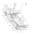
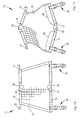
- Fig. 1 shows a broken area a rear area 1 of a station wagon.
- the rear area 1 is perspective about from the perspective of the broken-away left side Rear window shown. It has a roof 2 that is supported laterally by two C-pillars 3.
- a rear side window 5 In front of the C pillar 3 lies below the roof 2 and above a side wall 4 a rear side window 5 while behind the C-pillar 3 a further rear side window 6 is arranged is.
- the arrangement of the side windows 5, 6 is on the left Think side of the rear area 1 mirror image.
- the rear seat back 9 Between the lower edge of the roof 2 and the upper edge the rear seat back 9 is an opening 12 through which a passenger compartment in front of the rear seat back 9 the rear cargo area of the rear area 1 in Connection is established.
- the opening 12 is closed by a separating device 13.
- a sheet is part of the separating device 13 in the form of a trapezoidal-cut dividing network 14, which is bordered laterally by binding tapes 15 and the upper and lower edges of which are sewn on and welded tubular loop 16, 17 is formed.
- a strut leads through the loop 16 19, which with the loop 16 additionally, for example with the help of rivets not shown is connected to prevent that the strut 19 rotate in the loop 16 or in Longitudinal direction of the strut 19 can move.
- the strut 19 is tubular and contains it in their outward-facing ends energy-consuming Elements 22, the structure of which is shown in detail in FIG. 9 is.
- Fastening members are made of the energy-consuming element 22 23, the mushroom-shaped heads 24 wear. With these mushroom-shaped heads 24 are the fasteners 23 added in body-fixed T-slots 25.
- the lower edge with the strut 21 is with the help of two drawstrings 26 and unrecognizable hooks Eyelets 27 attached to the back 11 of the backrest 9th are attached.
- the drawstrings 26 have a limited stretch.
- the two struts 19 and 21 can be shortened in their effective length.
- the strut 19 and the strut 21 a medium Hinge 30, for example the strut 19 in a left Strut section 31 and a right strut section 32 divides.
- the strut 21 by the Hinge 30 in a left and a right strut section 33 and 34 divided.
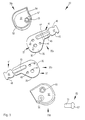
- the hinge 30 includes two identical hinge tabs 35a and 35b, which are used as sheet metal bending and stamping parts and two bowl-shaped hinged covers 36a and 36b, which are almost identical.
- the hinge bracket 35a is composed of a plate-shaped one Tab portion 37 with two parallel to each other Flat sides 38 and 39 and one starting from it in one piece Process 41 together.
- the thickness of the extension 41 is equal to the thickness of the tab portion 37, and this too is from a substantially flat flat side 42 and a parallel to this flat side 43 limited.
- the tab section 37 has a top view in the broadest sense approximately triangular shape with strongly rounded corners.
- the hinge bracket 35a is provided with an offset 44.
- the bend 44 has such a depth that the Middle plane between the flat sides 42 and 43 of the extension 41 is flush with the flat side 37.
- extension 41 runs parallel to one Level which is defined, for example, by the flat side 37.
- a longitudinal oval bead 45 provided that extends through the bend 44 extends and one end of which extends in the tab portion 37 and the other is located in the extension 41.
- the bead 45 is designed so that it comes from the flat sides 39 and 43 rises, i.e. is concave on the side where the Extension 41 according to the bend 44 against the flat side 38 is increased. This configuration is the best 5 can be seen.
- the two can be identical Hinge tabs 35a and 35b with their flat sides 38 for Plant are brought up while the associated appendages 41 are then on a common level, i.e. she point towards the parting surface on which the two flat sides 38 lie on top of each other, each with the same offset in opposite direction.
- the extension 41 contains in its opposite Edges a total of four roughly sawtooth-shaped Notches or incisions 46 that will be made later described way of fastening the relevant strut section 31 ... 34 serves.
- the tab portion 37 In the tab portion 37 are two cylindrical bores 47 and 48, and a threaded bore 49 included.
- the bore 47 is opposite, as can be seen in the figure the extension 41 clearly offset. It forms when assembled Hinge 30, as shown in FIG. 2, the hinge bore, through which a hinge pin 51 leads through Provide a closing or rivet head on both sides is.
- Hinge tabs 35a and 35b with their flat sides 38 on top of one another and are in the area of the hinge bore 37 the hinge pin 51 rotatable but otherwise rigid with each other are connected. Due to the hinge pin 41 can the two tabs 35a, 35b only have a rotational movement in execute a plane defined by the flat side 38 is.
- the other two flat sides 39 show when riveted Hinge 30 to the outside.
- the hinge covers 36a and 36b are bowl-shaped and consist of a substantially flat bottom 52 to which an endless peripheral side wall 53 is formed.
- the contour of the side wall 53 largely follows the outer contour of the tab portion 37, the side wall 53 in the area the bend 44 forms a straight wall 54.
- the side wall 53 is at its free, from the bottom 52 remote edge, provided with a recess 55 with which, as Fig. 2 shows, the outside of the tab portion 37 encompasses.
- the straight side wall 54 follows its free edge of the contour remote from the bottom 52 the flat side 43 and 39 in the area of the bend 44. Im assembled state is the tab portion 37 of the lid 36 closed, while the extension 41 under the wall 54 protrudes.
- a cylindrical extension 56 is formed on the base 52, whose axial length is dimensioned so that it is on the flat side 39 rests when the recess 55 also abuts the flat side 39.
- a countersunk screw leads through the conical bore thus obtained 59, which is screwed into the threaded bore 49.
- the cover 36 is attached to the relevant tab 35a or 35b fixed.
- the lid 36b contains in addition to the bore 57 another cylindrical bore 61 on the inside of the cover 52 by a short cylindrical collar 62 is surrounded.
- the bore 61 is aligned when the cover is installed 36b with the cylindrical bore 48. This in turn is located 3, can be seen above the Hinge bore 47 in such a place that the two extensions 41 extend to one another, if the bores 48, as can be seen in FIG. 2, are made to coincide with each other.
- the holes 48 in the two hinge tabs 35a and 35b serve to receive a cylindrical locking bolt 53, which is freely displaceable in the holes 48 is.
- a leaf spring 64 which in detail in 6, the locking bolt 63 in Biased towards bore 61.
- the length of the Locking bolt 63 is approximately twice the strength of the tab portion 37.
- an unlock button 65 which itself from a cylindrical shaft 66 and an actuating head 67 composed.
- the cylindrical shaft 66 With the cylindrical shaft 66 is the Release button in the cylindrical bore 41 longitudinally displaceable out and is guided by a claw spring washer 68, which sits on the shaft 66, against falling out secured.
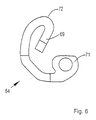
- the leaf spring 64 lies on the outside Page 39 on. It is shown in plan view in FIG. 6 and has a curved course with a spring arm 69 on, which presses against the locking bolt 63. On the opposite The leaf spring 64 ends in a mounting eye 71 above that when mounting on the threaded hole 49 comes to lie and between the tab portion 37 and the extension 56 of the cover 36 in question becomes.
- the outer contour of the leaf spring 64 essentially follows the inner contour of the lid 36, so that the Leaf spring 64 on the flat side 39 can not twist. Your strongly kinked area 72 abuts on the inside the straight side wall 54. This ensures that the free end 69 is always on the locking bolt 63 can act.
- the hinge bracket 35 shown in FIG. 2 The leaf spring 64 is shown on the left in a position in which the eye 71 is congruent with the threaded bore 49 during free arm 69 covers the bore 48. Then will the relevant lid 36 with the help of a corresponding Screw 59 screwed on, while the leaf spring 64 in the correct position on the relevant hinge bracket 35 is fixed. Then the two hinge tabs 35a and 35b in a position in which the Bores 48 are aligned with each other so that the locking bolt 63 can be inserted into this. Finally the other cover 36b is similarly placed on the still exposed hinge bracket 35b attached. Previously still the release button 65 inserted and with the Claw spring washer 68 secured.
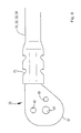
- Each of the strut sections 31 ... 34 consists of one Correspondingly long tubular steel section with a round Cross-section. At the end at which the connection later between the hinge 30 and the strut section 31 ... 34 to be manufactured, it is initially cylindrical Pipe over the length of a region 73, as can be seen in FIG. 7 is reshaped, so that a longitudinal oval cross section arises with a bulge 74 for receiving the bead 45.
- the cross section of the strut section corresponds to 31 ... 34 thus essentially the cross section of the relevant one Extension 41 at right angles in a sectional plane its longitudinal extent, namely over a length that is somewhat is greater than the length of the extension 41.
- connection with the hinge 30 happens as this can be seen in FIG. 8 by the strut in question 31 ... 34 with their end 73 ahead on the corresponding one Extension 41 of the hinge tab 35 is attached. thereupon are pressed into the strut 31 ... 34 notches 75, with what the wall material of the strut 31 ... 34 the sawtooth-shaped Notches 46 is embossed. This creates a backlash-free and tensile connection between the hinge bar 35 and the relevant strut 31 ... 34.
- the connection with the strut sections 31 ... 34 can be before or after assembly of the hinge 30 take place.
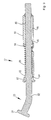
- a helical compression spring 89 located in the bore 88 is based on the one hand on the two with each other aligned tabs 83 and 84 and on the other hand on a ring 91 made of a solid material and with the help of beads in the two strut sections 31 and 32 is set.
- the anchoring member 23 is made by the compression spring 89 pressed outwards into the advanced position in which the tab 85 abuts the back of the ring 91.
- the axis of the hinge pin is in the use position 51 of both the upper hinge 30 and the lower hinge 30 parallel to the vehicle longitudinal axis aligned.
- separator 13 If the separator 13 is not needed, be to remove the lower drawstrings 26 with their Unhooked hooks from the eyes 27. Then the top one Strive with their anchoring members 23 out of the T-slots 25 pulled out. The separator 13 can now be completely be removed from the vehicle.
- the user can now, for example unlock the hinge 30 of the lower strut 21 by the release button 65 is pressed. This will the hinge 30 is released and, as detailed above is explained, can be folded.
- the beginning of the folding shows Fig. 11.
- the two strut sections When folded, the two strut sections have 31 and 32 in the immediate vicinity of the Hinge a distance that is greater than its diameter also corresponds to a strong finger, so not there is a risk of being crushed. This distance will reached because the hinge bore 47 relative to the extensions 41 is laterally offset.
- the lower one will also be Brace 21 fully folded in a similar manner. Then the upper strut is folded up 19 forth the separating net 14 on the folded strut 19 wound up until the resulting wrap on the folded Strut 21 arrives.
- the effective length of the struts 19 and 21 is through the folding has been reduced to half, with which the resulting one Wrap has a length that is significantly shorter than it corresponds to the width of the spanned security network 14.
- the folded and wound separation net 14 can now be easily within the To accommodate a motor vehicle.
- the separating net 14, 1, in the vicinity of the hinges 30 can be provided with a recess 98.
- a Storage device in the form of a on the separating device provided pocket serves to secure the folded Separating net in the stowed position.
Landscapes
- Engineering & Computer Science (AREA)
- Mechanical Engineering (AREA)
- Vehicle Step Arrangements And Article Storage (AREA)
- Tents Or Canopies (AREA)
- Body Structure For Vehicles (AREA)
Claims (41)
- Dispositif de séparation amovible (13) destiné à séparer dans un véhicule automobile une zone de chargement d'un habitacle,
avec un montant supérieur (19) pouvant être accroché de manière amovible dans le véhicule et dont la longueur active peut être réduite de plus qu'au moins 30 % de sa longueur maximale,
avec un montant inférieur (21) pouvant être accroché de manière amovible dans le véhicule et dont la longueur active peut être réduite de plus qu'au moins 30 % de sa longueur maximale, et
avec une partie plane, souple et essentiellement incapable de s'allonger (14), qui est fixée sur les montants supérieur et inférieur (19, 21). - Dispositif de séparation selon la revendication 1, caractérisé en ce que les montants supérieur et inférieur (19, 21) peuvent être repliés au moins une fois afin de réduire leur longueur réelle.
- Dispositif de séparation selon la revendication 1, caractérisé en ce que les montants inférieur et supérieur (19, 21) comportent chacun, afin de réduire leur longueur réelle, au moins une charnière (30), présentant un axe de charnière (51), qui subdivise le montant considéré (19, 21) en tronçons de montant (31 à 34).
- Dispositif de séparation selon la revendication 3, caractérisé en ce que, dans le cas d'une seule charnière (30) par montant (19, 21), les deux tronçons de montant (31 à 34) de chaque montant (19, 21) sont de même longueur.
- Dispositif de séparation selon la revendication 3, caractérisé en ce que les charnières (30) sont orientées les unes vers les autres de manière à ce que, lorsque le dispositif de séparation (13) est tendu, les deux charnières (30) se trouvent sur une droite qui est perpendiculaire aux deux montants (19, 21) parallèles entre eux.
- Dispositif de séparation selon la revendication 3, caractérisé en ce que les axes de charnière (51), lorsque le dispositif de séparation (13) est tendu, sont de préférence orientés horizontalement.
- Dispositif de séparation selon la revendication 3, caractérisé en ce que les tronçons de montant (31 à 34) voisins de chaque charnière (30) sont décalés par rapport à l'axe de charnière (51) afin que, lorsque le montant (19,21) est replié, ses tronçons de montant (31 à 34) puissent au moins être amenés dans une position où ils sont parallèles entre eux.
- Dispositif de séparation selon la revendication 3, caractérisé en ce que les tronçons de montant (31 à 34) voisins de chaque charnière (30) sont décalés par rapport à l'axe de charnière (51) afin que, lorsque le montant (19,21) est replié, ses tronçons de montant (31 à 34) présentent près de la charnière (30) une distance entre eux alors que les extrémités des tronçons de montant (31 à 34), à leurs extrémités éloignées de la charnière (30), sont jointifs.
- Dispositif de séparation selon la revendication 8, caractérisé en ce que la distance à proximité de la charnière (30) est d'au moins 1,5 cm.
- Dispositif de séparation selon la revendication 3, caractérisé en ce que la charnière (30) est une charnière simple avec seulement un axe de charnière (51).
- Dispositif de séparation selon la revendication 3, caractérisé en ce que la charnière (30) présente deux pattes de charnière (35) qui sont reliées ensemble de manière indissociable par un axe de charnière (51).
- Dispositif de séparation selon la revendication 11, caractérisé en ce que chaque patte de charnière (35) porte une prolongation (41) sur lequel est fixé le tronçon de montant (31 à 34) considéré.
- Dispositif de séparation selon la revendication 11, caractérisé en ce que, dans une position de la charnière (30) dans laquelle les prolongation (41) des pattes de charnière (35) se situent sur une droite, les axes de charnière (51) sont décalés latéralement, ce décalage étant mesuré dans un plan qui est perpendiculaire à l'axe de charnière (51).
- Dispositif de séparation selon la revendication 3, caractérisé en ce que la charnière (30) peut être verrouillée dans au moins une position.
- Dispositif de séparation selon la revendication 3, caractérisé en ce que la charnière (30) peut être verrouillée par obstacle de manière amovible.
- Dispositif de séparation selon la revendication 15, caractérisé en ce que la position correspond à l'extension rectiligne du montant (19, 21).
- Dispositif de séparation selon les revendications 11 et 15, caractérisé en ce que les pattes de charnière (35) présentent des ouvertures (48) qui sont alignées dans la position de verrouillage et en ce qu'il est prévu pour le verrouillage un goujon (63) pouvant être engagé dans les ouvertures (48).
- Dispositif de séparation selon la revendication 17, caractérisé en ce que le goujon (63) est précontraint par un ressort (64) dans sa position avancée.
- Dispositif de séparation selon la revendication 17, caractérisé en ce que le goujon (64) est associé à un organe de manoeuvre (65) qui est monté au niveau de l'une des pattes de charnière (35).
- Dispositif de séparation selon la revendication 11, caractérisé en ce que la patte de charnière (35) est dotée, pour son renforcement, d'une nervure (45) qui s'étend dans la prolongation (41).
- Dispositif de séparation selon la revendication 11, caractérisé en ce que la prolongation (41) de chaque patte de charnière (35) est coudée, de telle manière que les prolongations (41) se situent dans un plan commun auquel l'axe de charnière (51) est perpendiculaire.
- Dispositif de séparation selon la revendication 11, caractérisé en ce que chaque patte de charnière (35) présente sur son bord des encoches (46).
- Dispositif de séparation selon la revendication 11, caractérisé en ce que chaque patte de charnière (35) est associée à un couvercle (36) en forme de coque.
- Dispositif de séparation selon la revendication 3, caractérisé en ce que les tronçons de montant (31 à 34) sont de forme tubulaire.
- Dispositif de séparation selon la revendication 3, caractérisé en ce que les tronçons de montant (31 à 34) sont formés d'un tube cylindrique et en ce que le tube est aplati en section afin de recevoir la prolongation (41) de la patte de charnière (35) considérée.
- Dispositif de séparation selon la revendication 3, caractérisé en ce que les tronçons de montant (31 à 34), par l'une de leurs extrémités, sont enfichés sur la prolongation (41) et sont matés sur la prolongation (41), si bien que de la matière du tronçon de montant (31 à 34) est refoulée dans les encoches (46) marginales de la prolongation (41) considérée.
- Dispositif de séparation selon la revendication 3, caractérisé en ce que les tronçons de montant (31 à 34) sont faits dans un matériau pouvant se déformer en absorbant de l'énergie.
- Dispositif de séparation selon la revendication 1, caractérisé en ce que la partie plane (14) est constituée d'un filet.
- Dispositif de séparation selon la revendication 1, caractérisé en ce que la partie plane (14) est formée d'un film perforé.
- Dispositif de séparation selon la revendication 1, caractérisé en ce que les montants (19, 21) sont fixés sur la partie plane (14) sans pouvoir tourner.
- Dispositif de séparation selon la revendication 1, caractérisé en ce que les montants (19, 21) sont fixés sur la partie plane (14) sans pouvoir coulisser.
- Dispositif de séparation selon la revendication 3, caractérisé en ce que la partie plane (14) présente une découpe (98) au niveau de chacune des charnières (30).
- Dispositif de séparation selon la revendication 1, caractérisé en ce qu'il comporte un dispositif de fixation (95, 96) afin de fixer le dispositif de séparation dans sa position de rangement.
- Dispositif de séparation selon la revendication 33, caractérisé en ce que le dispositif de rangement (95, 96) est formé d'une pochette fixée de manière imperdable dans laquelle le dispositif de séparation (13) doit être rangé.
- Dispositif de séparation selon la revendication 34, caractérisé en ce que la pochette comprend deux parois de pochette flexibles (95, 96), chacune s'étendant le long d'un tronçon de montant (33, 34) de l'un des deux montants (21) et chacune pouvant être fixée au niveau du tronçon de montant (33, 34) considéré.
- Dispositif de séparation selon la revendication 35, caractérisé en ce que chaque paroi de pochette (95, 96) porte une partie d'une fermeture à glissière.
- Dispositif de séparation selon la revendication 1, caractérisé en ce qu'il comporte un troisième montant qui est reliés à la partie plane (14) et qui est construit de la même manière que les autres montants (19, 21).
- Dispositif de séparation selon la revendication 1, caractérisé en ce que le montant supérieur et/ou le montant inférieur (19, 21) sont dotés à leurs extrémités d'éléments d'ancrage (22).
- Dispositif de séparation selon la revendication 38, caractérisé en ce qu'au moins l'un des éléments d'ancrage (22) est guidé de manière à pouvoir coulisser longitudinalement par rapport au montant (19).
- Dispositif de séparation selon la revendication 1, caractérisé en ce que le montant inférieur (21) est doté à une certaine distance de ses extrémités d'éléments d'ancrage (26).
- Dispositif de séparation selon la revendication 40, caractérisé en ce que les éléments d'ancrage (26) prennent la forme de sangles ou de cordons.
Applications Claiming Priority (3)
| Application Number | Priority Date | Filing Date | Title |
|---|---|---|---|
| DE19944003 | 1999-09-14 | ||
| DE19944003A DE19944003C1 (de) | 1999-09-14 | 1999-09-14 | Faltbare Trenneinrichtung |
| PCT/DE2000/002949 WO2001019649A1 (fr) | 1999-09-14 | 2000-08-30 | Dispositif de separation pliable |
Publications (2)
| Publication Number | Publication Date |
|---|---|
| EP1128992A1 EP1128992A1 (fr) | 2001-09-05 |
| EP1128992B1 true EP1128992B1 (fr) | 2004-09-22 |
Family
ID=7921977
Family Applications (1)
| Application Number | Title | Priority Date | Filing Date |
|---|---|---|---|
| EP00965793A Expired - Lifetime EP1128992B1 (fr) | 1999-09-14 | 2000-08-30 | Dispositif de separation pliable |
Country Status (7)
| Country | Link |
|---|---|
| US (1) | US6595567B1 (fr) |
| EP (1) | EP1128992B1 (fr) |
| JP (1) | JP3623197B2 (fr) |
| KR (1) | KR100584103B1 (fr) |
| CN (1) | CN1144706C (fr) |
| DE (2) | DE19944003C1 (fr) |
| WO (1) | WO2001019649A1 (fr) |
Cited By (2)
| Publication number | Priority date | Publication date | Assignee | Title |
|---|---|---|---|---|
| EP2052918A2 (fr) | 2007-10-23 | 2009-04-29 | BOS GmbH & Co. KG | Dispositif de séparation repliable pour un véhicule automobile |
| DE202008010747U1 (de) | 2008-08-08 | 2009-12-17 | Bos Gmbh & Co. Kg | Trennvorrichtung für einen Fahrzeuginnenraum eines Kraftfahrzeugs |
Families Citing this family (38)
| Publication number | Priority date | Publication date | Assignee | Title |
|---|---|---|---|---|
| DE10054080C1 (de) * | 2000-10-31 | 2001-11-08 | Butz Peter Verwaltung | Sicherheitsnetz zur lösbaren Anbringung in einem Fahrzeug |
| FR2835530B1 (fr) | 2002-02-07 | 2004-04-09 | Inst Francais Du Petrole | Procede integre de desulfuration d'un effluent de craquage ou de vapocraquage d'hydrocarbures |
| US7048086B2 (en) * | 2002-08-26 | 2006-05-23 | Fujitsu Ten Limited | Vehicle protection apparatus at collision time |
| DE10242510B4 (de) * | 2002-09-12 | 2005-12-08 | Bos Gmbh & Co. Kg | Kfz-Sicherheitseinrichtung, insbesondere Trennnetz |
| US6962382B2 (en) * | 2003-05-23 | 2005-11-08 | David Scarlett | Barrier system |
| US7017965B2 (en) * | 2003-08-07 | 2006-03-28 | Bos Gmbh & Co. Kg | Motor-vehicle cargo net |
| DE202004007743U1 (de) * | 2004-05-11 | 2005-09-22 | Reum Protec Gmbh | Befestigungseinrichtung, insbesondere für eine Sicherheitsnetzanordnung zum Schutz des Fahrgastraumes von Kombi-Pkw's |
| DE202004008488U1 (de) * | 2004-05-25 | 2005-10-06 | Reum Protec Gmbh | Aufnahmevorrichtung für ein Sicherheitsnetz |
| NZ554018A (en) | 2004-09-09 | 2009-06-26 | Teva Pharma | Process for preparation of trifluoroacetyl glatiramer acetate using purified hydrobromic acid |
| DE102004050546B4 (de) | 2004-10-16 | 2022-02-24 | Bayerische Motoren Werke Aktiengesellschaft | Rückhalteeinrichtung für Gepäckstücke in einem Fahrzeug |
| DE102006034635A1 (de) * | 2006-07-27 | 2008-01-31 | Dr.Ing.H.C. F. Porsche Ag | Schutzvorrichtung für einen Laderaum |
| US20080042462A1 (en) * | 2006-08-18 | 2008-02-21 | Kevin Scotton | Collapsible tubing device for automobile shade |
| EP2008877A1 (fr) * | 2007-06-29 | 2008-12-31 | Ford Global Technologies, LLC | Filet à bagage doux |
| US20090057637A1 (en) * | 2007-08-30 | 2009-03-05 | Galla Paul V | Mounting Straps for Barriers |
| FR2932750B1 (fr) | 2008-06-18 | 2012-05-11 | Cera | Dispositif de protection contre la projection de bagages d'un compartiment a bagages de vehicule automobile |
| US8403615B1 (en) | 2008-08-20 | 2013-03-26 | Bruno Independent Living Aids, Inc. | Vehicle lift barrier |
| US20100244479A1 (en) * | 2009-03-25 | 2010-09-30 | International Truck Intellectual Property Company, Llc | Sliding bar assembly for use in cargo storage applications |
| WO2012117540A1 (fr) | 2011-03-02 | 2012-09-07 | トヨタ自動車株式会社 | Structure d'aménagement de composants pour rail latéral de toit |
| KR20120114995A (ko) * | 2011-04-08 | 2012-10-17 | 현대자동차주식회사 | 배리어 네트 장착 구조 |
| EP2674333B1 (fr) | 2012-06-11 | 2014-12-24 | Volvo Car Corporation | Diviseur de compartiment pliable pour véhicule |
| EP2703533A1 (fr) | 2012-09-04 | 2014-03-05 | Volvo Car Corporation | Filet de cargaison |
| US8714591B1 (en) * | 2013-02-06 | 2014-05-06 | Honda Motor Co., Ltd. | Vehicles, net assemblies, and clampers therefor |
| CN103437924B (zh) * | 2013-08-15 | 2015-06-24 | 北京动力机械研究所 | 一种用于多余物防护的半柔性机构 |
| US9676339B2 (en) * | 2015-04-01 | 2017-06-13 | Ford Global Technologies, Llc | Versatile tonneau cover and storage system for a motor vehicle |
| US20160339846A1 (en) * | 2015-05-18 | 2016-11-24 | Ford Global Technologies, Llc | Integrated cargo cover |
| CN105730349B (zh) * | 2016-03-08 | 2018-10-26 | 福建省汽车工业集团云度新能源汽车股份有限公司 | 一种可调节的汽车行李舱阻隔装置 |
| KR101795575B1 (ko) * | 2016-07-28 | 2017-11-09 | 주식회사 서연이화 | 차량용 베리어 네트 |
| KR101795561B1 (ko) * | 2016-07-28 | 2017-11-09 | 주식회사 서연이화 | 차량용 베리어 네트 |
| KR101795572B1 (ko) * | 2016-07-29 | 2017-11-09 | 주식회사 서연이화 | 차량용 베리어 네트 |
| KR101795565B1 (ko) * | 2016-07-29 | 2017-11-09 | 주식회사 서연이화 | 차량용 베리어 네트 |
| CN106627386B (zh) * | 2016-09-28 | 2018-09-14 | 东莞市联洲知识产权运营管理有限公司 | 一种新能源汽车用具有分隔装置的后备箱 |
| DE102017206905B4 (de) | 2017-04-25 | 2025-05-08 | Bayerische Motoren Werke Aktiengesellschaft | Gepäckraumabdeckung und Abtrenneinrichtung |
| US10202093B1 (en) | 2017-05-02 | 2019-02-12 | Brian Gethard | Barrier for an interior cab of vehicle |
| DE102018133161A1 (de) | 2018-12-20 | 2020-06-25 | Bayerische Motoren Werke Aktiengesellschaft | Rückhalteeinrichtung für Gepäckstücke |
| CN111231883A (zh) * | 2020-03-17 | 2020-06-05 | 尹立杰 | 一种车用隔离装置 |
| CN115027368A (zh) * | 2022-05-11 | 2022-09-09 | 浙江吉利控股集团有限公司 | 一种行李箱隔板及车辆 |
| DE102023110673A1 (de) * | 2023-04-26 | 2024-10-31 | Bayerische Motoren Werke Aktiengesellschaft | Trennanordnung und Kraftfahrzeug mit derartiger Trennanordnung |
| DE102023127296B3 (de) | 2023-10-06 | 2024-08-22 | Macauto Industrial Co., Ltd. | Laderaumabdeckung mit veränderlicher länge |
Family Cites Families (21)
| Publication number | Priority date | Publication date | Assignee | Title |
|---|---|---|---|---|
| US2565997A (en) * | 1949-08-09 | 1951-08-28 | Pittsburgh Steel Co | Load bracing frame |
| US2997331A (en) * | 1958-02-21 | 1961-08-22 | Donald F Kudner | Vehicle guard partition |
| US2982579A (en) * | 1958-03-19 | 1961-05-02 | Sidney D Greenwald | Adjustable and removable partitioning device for automobiles |
| US2998279A (en) * | 1959-01-09 | 1961-08-29 | Mateny Henry | Vehicle divider |
| US3044821A (en) * | 1959-10-27 | 1962-07-17 | Clarice B Wicker | Automobile safety barrier |
| US3049373A (en) * | 1961-04-03 | 1962-08-14 | William C Biggers | Safety guard attachment for the tailgate openings of station wagon vehicles |
| US3789439A (en) * | 1972-10-27 | 1974-02-05 | Cross River Prod Inc | Foldable and adjustable crib |
| US4281487A (en) * | 1979-08-06 | 1981-08-04 | Koller Karl S | Energy absorbing load carrying strut and method of providing such a strut capable of withstanding cyclical loads exceeding its yield strength |
| US4819300A (en) * | 1987-04-13 | 1989-04-11 | Hartwell Corporation | Strut assembly |
| US5215288A (en) * | 1991-08-12 | 1993-06-01 | Roadway Express, Inc. | Load bar for a variably positioned bulkhead |
| USD348421S (en) * | 1993-02-22 | 1994-07-05 | Dexter Timothy J | Truck bed cargo restraining net |
| DE4336380C2 (de) | 1993-10-25 | 1995-08-10 | Baumeister & Ostler Gmbh Co | Sicherheitsnetzanordnung |
| US5427486A (en) * | 1994-03-17 | 1995-06-27 | Green; Gerald D. | Adjustable load securing device for vehicles |
| US5542151A (en) * | 1995-05-01 | 1996-08-06 | Century Products Company | Rotatable bending joint for collapsible playpen |
| DE19641794A1 (de) * | 1995-10-24 | 1997-04-30 | Volkswagen Ag | Rückhalteeinrichtung |
| DE19540934C2 (de) * | 1995-11-03 | 1998-10-29 | Opel Adam Ag | Trennwand zum variablen Abtrennen eines Ladebereiches eines Kraftfahrzeuges von einem Fahrgastraum |
| US5730542A (en) * | 1997-05-14 | 1998-03-24 | Top Fortune Ltd. | Joint for a playen |
| DE19730801C1 (de) * | 1997-07-18 | 1999-03-25 | Baumeister & Ostler Gmbh Co | Einfaches Sicherheitsnetz mit Haken zum Einhängen |
| DE19731326C2 (de) * | 1997-07-22 | 2003-03-20 | Bayerische Motoren Werke Ag | Windschutz für ein Cabriolet |
| GB9721287D0 (en) * | 1997-10-07 | 1997-12-10 | Tomy Uk Ltd | Improvements in apparatus for use by babies and young children |
| US6371342B2 (en) * | 1998-07-21 | 2002-04-16 | Johnson Controls Technology Company | Cargo retention system |
-
1999
- 1999-09-14 DE DE19944003A patent/DE19944003C1/de not_active Expired - Fee Related
-
2000
- 2000-08-30 DE DE50007886T patent/DE50007886D1/de not_active Expired - Lifetime
- 2000-08-30 US US09/831,973 patent/US6595567B1/en not_active Expired - Lifetime
- 2000-08-30 EP EP00965793A patent/EP1128992B1/fr not_active Expired - Lifetime
- 2000-08-30 CN CNB008019509A patent/CN1144706C/zh not_active Expired - Fee Related
- 2000-08-30 WO PCT/DE2000/002949 patent/WO2001019649A1/fr not_active Ceased
- 2000-08-30 KR KR1020017005950A patent/KR100584103B1/ko not_active Expired - Fee Related
- 2000-08-30 JP JP2001523251A patent/JP3623197B2/ja not_active Expired - Fee Related
Cited By (4)
| Publication number | Priority date | Publication date | Assignee | Title |
|---|---|---|---|---|
| EP2052918A2 (fr) | 2007-10-23 | 2009-04-29 | BOS GmbH & Co. KG | Dispositif de séparation repliable pour un véhicule automobile |
| DE102007052228A1 (de) | 2007-10-23 | 2009-06-10 | Bos Gmbh & Co. Kg | Zusammenlegbare Trenneinrichtung für ein Kraftfahrzeug |
| EP2052918A3 (fr) * | 2007-10-23 | 2010-03-17 | BOS GmbH & Co. KG | Dispositif de séparation repliable pour un véhicule automobile |
| DE202008010747U1 (de) | 2008-08-08 | 2009-12-17 | Bos Gmbh & Co. Kg | Trennvorrichtung für einen Fahrzeuginnenraum eines Kraftfahrzeugs |
Also Published As
| Publication number | Publication date |
|---|---|
| DE50007886D1 (de) | 2004-10-28 |
| CN1144706C (zh) | 2004-04-07 |
| KR20010089440A (ko) | 2001-10-06 |
| WO2001019649A1 (fr) | 2001-03-22 |
| EP1128992A1 (fr) | 2001-09-05 |
| DE19944003C1 (de) | 2001-03-22 |
| CN1321126A (zh) | 2001-11-07 |
| JP3623197B2 (ja) | 2005-02-23 |
| KR100584103B1 (ko) | 2006-05-30 |
| JP2003509270A (ja) | 2003-03-11 |
| US6595567B1 (en) | 2003-07-22 |
Similar Documents
| Publication | Publication Date | Title |
|---|---|---|
| DE19944003C1 (de) | Faltbare Trenneinrichtung | |
| EP1060956B1 (fr) | Dispositif de séparation à force de rappel variable | |
| DE19546646A1 (de) | Rückenlehne für Kraftfahrzeugsitze | |
| EP0754594B1 (fr) | Rideau écran avec sécurité élevée en cas d'accident | |
| DE3631488A1 (de) | Abdeckplatte fuer einen fahrzeug-innenraum | |
| EP1102691B1 (fr) | Filet de retenue simple muni de bandes de retenue | |
| WO1988001950A1 (fr) | Toit decapotable pour voitures tout-terrain | |
| EP1435311B1 (fr) | Dispositif de recouvrement de compartiment à bagages comportant des pieces d'angle mobiles | |
| EP1889740A1 (fr) | Cloison étanche pour un véhicule automobile | |
| DE19735463C1 (de) | Sicherheitsnetz mit erhöhter Festigkeit der Wickelwelle | |
| EP3210808B1 (fr) | Enrouleur de bâche et véhicule utilitaire équipé d'une bâche | |
| EP2330020B1 (fr) | Recouvrement latéral d'un châssis de véhicule utilitaire | |
| DE60017403T2 (de) | Sperrnetz für kraftfahrzeuge | |
| DE19650768C2 (de) | Sicherheitsnetzanordnung mit vereinfachter Bedienung | |
| EP3862246A1 (fr) | Dispositif de protection destiné à l'emplacement dans un espace intermédiaire entre deux véhicules accouplés | |
| DE2647104C3 (de) | Lagerung für eine schwenkbare Abdeckplatte über dem Kofferraum von Kraftfahrzeugen | |
| DE2656249A1 (de) | Aufprallschutzvorrichtung fuer die insassen von fahrzeugen, insbesondere von personenkraftfahrzeugen | |
| DE19730802C1 (de) | Sicherheitsnetzanordnung mit versenkbaren Karosseriehaltern | |
| DE19843044B4 (de) | Ladegutrückhaltevorrichtung für ein Kraftfahrzeug | |
| DE19651692A1 (de) | Heckklappenanlenkung für Kraftfahrzeuge | |
| EP4265480B1 (fr) | Ensemble couvercle de compartiment à bagages pour un véhicule, compartiment à bagages d'un véhicule et véhicule | |
| EP0882612B1 (fr) | Bâche coulissant pour carrosseries de véhicule et conteneurs | |
| DE3107001A1 (de) | Tragvorrichtung zur anbringung auf dem dach eines fahrzeuges, insbesondere eines personenkraftwagens | |
| EP0952041A2 (fr) | Véhicule automobile avec au moins un filet de retenue à rouleau attachable entre les compartiments passagers et bagages | |
| DE19612019A1 (de) | Fahrzeugtüre mit gelenkig verbundenen und teilweise lösbaren Aufprallschutzkörpern |
Legal Events
| Date | Code | Title | Description |
|---|---|---|---|
| PUAI | Public reference made under article 153(3) epc to a published international application that has entered the european phase |
Free format text: ORIGINAL CODE: 0009012 |
|
| 17P | Request for examination filed |
Effective date: 20010601 |
|
| AK | Designated contracting states |
Kind code of ref document: A1 Designated state(s): AT BE CH CY DE DK ES FI FR GB GR IE IT LI LU MC NL PT SE |
|
| AX | Request for extension of the european patent |
Free format text: AL;LT;LV;MK;RO;SI |
|
| 17Q | First examination report despatched |
Effective date: 20030120 |
|
| GRAP | Despatch of communication of intention to grant a patent |
Free format text: ORIGINAL CODE: EPIDOSNIGR1 |
|
| RAP1 | Party data changed (applicant data changed or rights of an application transferred) |
Owner name: BOS GMBH & CO. KG |
|
| GRAS | Grant fee paid |
Free format text: ORIGINAL CODE: EPIDOSNIGR3 |
|
| GRAA | (expected) grant |
Free format text: ORIGINAL CODE: 0009210 |
|
| AK | Designated contracting states |
Kind code of ref document: B1 Designated state(s): DE FR GB IT |
|
| REG | Reference to a national code |
Ref country code: GB Ref legal event code: FG4D Free format text: NOT ENGLISH |
|
| GBT | Gb: translation of ep patent filed (gb section 77(6)(a)/1977) |
Effective date: 20040922 |
|
| REG | Reference to a national code |
Ref country code: IE Ref legal event code: FG4D Free format text: GERMAN |
|
| REF | Corresponds to: |
Ref document number: 50007886 Country of ref document: DE Date of ref document: 20041028 Kind code of ref document: P |
|
| LTIE | Lt: invalidation of european patent or patent extension |
Effective date: 20040922 |
|
| REG | Reference to a national code |
Ref country code: IE Ref legal event code: FD4D |
|
| ET | Fr: translation filed | ||
| PLBE | No opposition filed within time limit |
Free format text: ORIGINAL CODE: 0009261 |
|
| STAA | Information on the status of an ep patent application or granted ep patent |
Free format text: STATUS: NO OPPOSITION FILED WITHIN TIME LIMIT |
|
| 26N | No opposition filed |
Effective date: 20050623 |
|
| PGFP | Annual fee paid to national office [announced via postgrant information from national office to epo] |
Ref country code: GB Payment date: 20090827 Year of fee payment: 10 |
|
| PGFP | Annual fee paid to national office [announced via postgrant information from national office to epo] |
Ref country code: IT Payment date: 20090820 Year of fee payment: 10 |
|
| GBPC | Gb: european patent ceased through non-payment of renewal fee |
Effective date: 20100830 |
|
| PG25 | Lapsed in a contracting state [announced via postgrant information from national office to epo] |
Ref country code: IT Free format text: LAPSE BECAUSE OF NON-PAYMENT OF DUE FEES Effective date: 20100830 |
|
| PG25 | Lapsed in a contracting state [announced via postgrant information from national office to epo] |
Ref country code: GB Free format text: LAPSE BECAUSE OF NON-PAYMENT OF DUE FEES Effective date: 20100830 |
|
| REG | Reference to a national code |
Ref country code: FR Ref legal event code: PLFP Year of fee payment: 16 |
|
| PGFP | Annual fee paid to national office [announced via postgrant information from national office to epo] |
Ref country code: FR Payment date: 20150629 Year of fee payment: 16 |
|
| PGFP | Annual fee paid to national office [announced via postgrant information from national office to epo] |
Ref country code: DE Payment date: 20160831 Year of fee payment: 17 |
|
| REG | Reference to a national code |
Ref country code: FR Ref legal event code: ST Effective date: 20170428 |
|
| PG25 | Lapsed in a contracting state [announced via postgrant information from national office to epo] |
Ref country code: FR Free format text: LAPSE BECAUSE OF NON-PAYMENT OF DUE FEES Effective date: 20160831 |
|
| REG | Reference to a national code |
Ref country code: DE Ref legal event code: R119 Ref document number: 50007886 Country of ref document: DE |
|
| PG25 | Lapsed in a contracting state [announced via postgrant information from national office to epo] |
Ref country code: DE Free format text: LAPSE BECAUSE OF NON-PAYMENT OF DUE FEES Effective date: 20180301 |