EP1129039B1 - Verfahren und vorrichtung zum pressen eines külbels - Google Patents
Verfahren und vorrichtung zum pressen eines külbels Download PDFInfo
- Publication number
- EP1129039B1 EP1129039B1 EP00947993A EP00947993A EP1129039B1 EP 1129039 B1 EP1129039 B1 EP 1129039B1 EP 00947993 A EP00947993 A EP 00947993A EP 00947993 A EP00947993 A EP 00947993A EP 1129039 B1 EP1129039 B1 EP 1129039B1
- Authority
- EP
- European Patent Office
- Prior art keywords
- parison
- mould
- neck
- press ram
- cavity
- Prior art date
- Legal status (The legal status is an assumption and is not a legal conclusion. Google has not performed a legal analysis and makes no representation as to the accuracy of the status listed.)
- Expired - Lifetime
Links
- 238000003825 pressing Methods 0.000 title claims abstract description 52
- 238000000034 method Methods 0.000 title claims abstract description 19
- 239000006060 molten glass Substances 0.000 claims abstract description 17
- 239000011521 glass Substances 0.000 claims description 31
- 238000007789 sealing Methods 0.000 claims description 14
- 238000006073 displacement reaction Methods 0.000 claims description 5
- 238000004519 manufacturing process Methods 0.000 claims description 3
- 230000035515 penetration Effects 0.000 claims description 2
- 238000007496 glass forming Methods 0.000 claims 3
- 230000001276 controlling effect Effects 0.000 claims 1
- 230000001105 regulatory effect Effects 0.000 claims 1
- 230000006835 compression Effects 0.000 description 5
- 238000007906 compression Methods 0.000 description 5
- 238000000465 moulding Methods 0.000 description 5
- 230000015572 biosynthetic process Effects 0.000 description 3
- 238000003780 insertion Methods 0.000 description 3
- 230000037431 insertion Effects 0.000 description 3
- 238000007664 blowing Methods 0.000 description 2
- 235000019993 champagne Nutrition 0.000 description 2
- 230000000694 effects Effects 0.000 description 2
- 238000010586 diagram Methods 0.000 description 1
- 238000009826 distribution Methods 0.000 description 1
- 239000006066 glass batch Substances 0.000 description 1
- 239000007788 liquid Substances 0.000 description 1
- 238000005498 polishing Methods 0.000 description 1
- 238000007493 shaping process Methods 0.000 description 1
- 230000007704 transition Effects 0.000 description 1
Images




Classifications
-
- C—CHEMISTRY; METALLURGY
- C03—GLASS; MINERAL OR SLAG WOOL
- C03B—MANUFACTURE, SHAPING, OR SUPPLEMENTARY PROCESSES
- C03B9/00—Blowing glass; Production of hollow glass articles
- C03B9/13—Blowing glass; Production of hollow glass articles in gob feeder machines
- C03B9/193—Blowing glass; Production of hollow glass articles in gob feeder machines in "press-and-blow" machines
- C03B9/1932—Details of such machines, e.g. plungers or plunger mechanisms for the press-and-blow machine, cooling of plungers
- C03B9/1936—Hydraulic or pneumatic displacement means of the plunger
-
- C—CHEMISTRY; METALLURGY
- C03—GLASS; MINERAL OR SLAG WOOL
- C03B—MANUFACTURE, SHAPING, OR SUPPLEMENTARY PROCESSES
- C03B9/00—Blowing glass; Production of hollow glass articles
- C03B9/13—Blowing glass; Production of hollow glass articles in gob feeder machines
- C03B9/193—Blowing glass; Production of hollow glass articles in gob feeder machines in "press-and-blow" machines
- C03B9/1932—Details of such machines, e.g. plungers or plunger mechanisms for the press-and-blow machine, cooling of plungers
-
- C—CHEMISTRY; METALLURGY
- C03—GLASS; MINERAL OR SLAG WOOL
- C03B—MANUFACTURE, SHAPING, OR SUPPLEMENTARY PROCESSES
- C03B9/00—Blowing glass; Production of hollow glass articles
- C03B9/30—Details of blowing glass; Use of materials for the moulds
- C03B9/32—Giving special shapes to parts of hollow glass articles
Definitions
- the invention relates to a method according to the preamble of claim 1 and a device according to the preamble of claim 5.
- the Width depends on the respective working end position of the press ram. In this gap can be used in certain operating situations when pressing glass mass intrude in an undesirable manner.
- the guide ring is radially in one Retaining groove of the muzzle tool held. The guide ring points to his the recess facing end a form ring for forming the axially outer sealing edge of the mouth of the parison.
- From GB 2 178 421 A is a device for adjusting the item mass known per se on a feeder.
- the invention has for its object the formation of the mouth of the parison to improve.
- This task is related to the method by the features of the claim 1 solved. Thanks to its attachment to the muzzle tool, the Press ram now very precisely always the same working end position independently on the mass of the lot and the volume of the recess of the preform. This leads to constant internal contours of the mouths of the parisons. Because moreover, the entire axially outer sealing edge of the mouth is not shaped more by the guide ring, but by the press die itself , the slightly conical guide section at the base of the press ram can be made more conical. This will pull out relieved of the press ram from the finished pressed parison and one Damage to the inner surface of the parison is prevented. The parison is pressed in two stages.
- the parison In the first stage, the parison is replaced by the Pre-pressed to its final working position, and in the second Stage, the parison is finished pressed by the pressing element.
- the result is a parison with an ideally pressed, undamaged mouth and also very cheap glass distribution.
- the invention is particularly suitable for use with so-called I.S. (Individual Section) -press-blow-glass molding machines.
- the features of claim 2 keep the pressing element comparatively long in contact with the glass.
- the loading opening according to claim 3 can be funnel-shaped to the to improve the trouble-free insertion of the item into the recess and to facilitate.
- a separate hopper can be used in most cases avoid.
- Such a loading funnel would otherwise be a separate element to move over the loading opening for loading and to close again after loading removing any. This would mean higher structural and operational costs.
- the loading opening according to claim 6 can preferably be funnel-shaped be to facilitate the insertion of the item into the recess and improve.
- the features of claim 7 are particularly in the manufacture of Wide-necked glasses are an advantage.
- the closed preform can be opened in a special way easy way to hold. This tumbler is required during the Pressing process, where the pressing forces want to open the individual parts of the preform to prevent such opening. Such opening would preform gaps arise in which glass mass are pressed in an undesirable manner could.
- Corresponding between the block shape and the mouth tool can also DE 32 32 288 C1 arranged a longitudinally divided preform center piece his. That way you could use a block shape too Narrow-necked glasses are made.
- the axially outer sealing edge Muzzle no longer from a guide ring in the muzzle tool or of the muzzle tool, but completely by an element of the Press die shaped. This increases the precision of the muzzle formation.
- the working end position can be particularly constructive simply realize.
- the ram is used for parison forming particularly important last section in the radial direction a cylindrical shaft surface guided exactly radially.
- the centering ring is also when the mouth tool is open held securely in the muzzle tool.
- the muzzle tool is only released during operation when the finished molded part is released Hollow glass object opened.
- Fig. 1 the lower part of a closed preform 1 is shown.
- the Preform 1 has a longitudinally divided muzzle tool 2 with muzzle tool halves 3 and 4 and preform halves 5 and 6.
- a guide ring 8 In a radial holding groove 7 of the mouth tool 2 is a guide ring 8 that is not longitudinally divided held.
- the guide ring 8 has a central passage 9 for a press ram 10 on.
- the ram is not on a piston rod 11 further drawn, known piston-cylinder unit mounted and in the Directions of a double arrow 12 can be raised and lowered.
- the press ram 10 has a punch tip 13, a distinctly conical section 14 and one a foot of the ram 10 forming slightly conical section 15. At the foot 15 there is a larger diameter, cylindrical shaft 16 of the ram 10.
- the preform halves 5, 6 have a loading opening at the top provided according to Fig. 1 of EP 0 327 240 A1 after the introduction the item in a recess 17 of the preform 1 for the pressing process a preform base can be closed.
- Fig. 1 the ram 10 is drawn in its uppermost working position, that without any further mechanical stop solely through the deformation resistance of the molten glass is defined in the recess 17.
- This has the consequence that changing axial zones in normal operation the slightly conical section 15 of the press ram 10 in the working end position of the ram 10, the central passage 9 of the guide ring 8th are opposite. This leads to ring gaps of different widths between the central passage 9 and the slightly conical section 15 and accordingly greater or lesser risk that molten liquid in this annular gap Glass is pressed in during the pressing process.
- a finished pressed parison 18 is drawn in the recess 17.
- the parison has a mouth 19 at the bottom, the axially outer edge 20 thereof formed by an annular recess 21 formed at the top in the guide ring 8 becomes. Since the guide ring 8 is not longitudinally divided, the axially outer edge has 20 of the mouth 19 no longitudinal seams. This is for a secure closure of the finished hollow glass object advantageous.
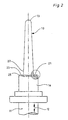
- the press ram 10 according to FIG. 2 is not on its length more divided into sections 14, 15 according to FIG. 1, but on its whole Length uniformly conical throughout. From procedural However, reasons can also apply to the press ram according to the invention 10 a taper varying along its length can be provided. In any case, according to the invention, the taper can be chosen so large that itself after completion of the parison 18 of the ram 10 without damage pull the inner surface of the parison out of the parison.
- annular end face 23 of the Shaft 16 is, adjacent to the foot 22, the annular recess 21 for forming the axially outer edge 20 of the mouth 19 is formed. Otherwise, the 4, 5 and 9 for defining the working end position of the ram 10 on a stop surface 24 of the closed Muzzle tool 2.
- the annular end face 23 goes radially outward into a chamfer 25 on the cylindrical shaft 16.
- FIG. 3 shows the preform 1 with the closed die halves 3, 4 and also closed preform halves 5, 6.
- the ram 10 is located in an axial intermediate position, the so-called loading position, in the the punch tip 13 has penetrated the muzzle tool 2 and a short one Piece has penetrated into the recess 17 of the preform halves 5, 6.
- a loading opening 26 is formed in the upper region of the preform halves 5, 6.
- the loading opening 26 is essentially funnel-shaped with conical wall sections 27 and 28 trained. Between the conical wall sections 27, 28 there is a cylindrical receiving section 29.
- a drop outlet 31 of a feeder 32 Coaxial with a longitudinal axis 30 of the preform 1 is above the loading opening 26 a drop outlet 31 of a feeder 32 is arranged, in which there is molten Glass 33 is located.
- a plunger 34 arranged in the directions of the double arrow 35 in in a known manner can be raised and lowered by a drive 36.
- the Drive 36 is controlled via a line 37 so that the molten Glass 33 emerges from the drop outlet 31 in such a way that ultimately item 38 result in molten glass of as constant a mass as possible. From the Drop outlet 31 occurs in a manner known per se a strand of the molten Glasses 33 depending on the vertical movement of the plunger 34.
- a centering ring 41 In the holding groove 7 of the mouth tool 2 in Fig. 3 is the radially outer part a centering ring 41 not divided longitudinally.
- the centering ring 41 has a cylindrical central passage 42 which at the bottom in an extension 43rd the centering ring 41 passes.
- FIG. 4 shows a later process state than that in FIG. 3.
- the guide sleeve 45 has at the bottom and radially outside a chamfer 46 on the insertion of the loading sleeve 45 in the conical Wall portion 27 and the cylindrical receiving portion 29 facilitated.
- the guide sleeve 45 is finally drawn in FIG. 4 Arranged way with a sliding fit in the receiving portion 29 and finds its lower axial stop on an annular stop surface 47 of the preform halves 5, 6. This stop position is indicated by a the assembly 44, 45, 48 moving mechanism up to maintain subsequent demolding of the finished parison.
- the pressing element 44 is a piston rod of a pneumatic piston-cylinder unit in this case 48 trained.
- a piston 49 attached to the pressing member 44 Unit 48 is displaceable in a cylinder 50 of unit 48.
- the cylinder 50 is attached to the guide sleeve 45, for example by a weld 51.
- a first cylinder chamber 52 has a line 53 and a second cylinder chamber 54 connected to a line 55.
- a sensor 56 of a displacement sensor 57 is connected to the piston 49.
- the pioneer 57 is attached to the cylinder 50.
- the sensor 56 is sealed by a Opening 58 of the cylinder 50 is slidably guided.
- the Sensor 56 is also with a grinder 59 of a potentiometer 60 Weggers 57 connected.
- An output line 61 of the displacement sensor 57 is included an electrical controller 62, from the output of which line 37 (see Fig. 3) goes off.
- the pressing element 44 dips due to the pressure effect the compression spring 64 and its own weight as deep as possible into the recess 17 a. Then the ram 10 is drawn from its in Fig. 3 Loading position moved up. The chamfer 25 of the cylindrical thread Shank 16 in the extension 43 of the centering ring 41 and centered thereby the ram 10 relative to the mouth shape 1. From there strict radial guidance of the shaft 16 in the central passage 42 of the Centering ring 41 instead. The centering of the ram is correspondingly precise 10 relative to the preform 1.
- the ram 10 is still in its uppermost working end position, in which the annular end face 23 on the stop surface 24 is present.
- the directional valve 65 in Fig. 7 in its lower Switched position, the line 55 and thus the second cylinder chamber 54 with a pneumatic pressure line 69 connected.
- This resulted in the Piston 49 and the pressing element 44 from the position shown in Fig. 4 in the the lowest position shown in FIG. 5 has been shifted.
- the grinder 59 also reaches its lowest position relative to the potentiometer 60.
- This stamp position information reaches the output line 61 in the electrical control 62, which may be via the stroke of the plunger 34 an adjustment of the mass of the item 38 causes.
- the parison 18 Since the parison 18 is now pressed, it can be removed from the mold. This will First, the directional control valve 65 in its upper switching position shown in FIG. 7 switched and the second cylinder chamber 54 vented. Then the ram 10 from its working end position shown in FIG. 5 to its working position in FIG. 6 drawn lowest transfer end position withdrawn. After that the Assembly of pressing element 44, guide sleeve 45 and piston-cylinder unit 48 removed. Finally, the preform halves 5, 6 are known per se Open way.
- the press ram 10 is now completely outside of the parison 18 and is lowered so far that the mouth tool 2 with the centering ring 41 and the parison 18 in a not previously drawn, known final molding station can be transferred to the press-blow glass molding machine. This happens usually in I.S. glass molding machines by a so-called Invert mechanism that the mouth tool 2 and the parison 18 by 180 ° pivots about a horizontal axis into the finishing station, where the parison 18 is then arranged with the mouth 19 upwards.
- the control of the lines 53, 55 of the cylinder 50 can also be based on others Way done.
- the lines 53, 55 are shown in FIG Way connected with a 4-way / 2-position valve 71.
- 8 drawn upper switching position of the directional control valve 71 is the first cylinder space 52 pressurized with compressed air. This causes the piston 49 to the pressing element 44 is moved to its uppermost end position.
- a Compression spring corresponding to the compression spring 64 in FIGS. 4 and 5 is in this Case not required. Rather, the cylinder 50 is double-acting and connected. The pressing element 44 and the piston 49 remain in this top position even if the assembly 44, 45, 48 on the meantime with the item 38 filled preform 1 is placed.
- This top one Position of the pressing element 44 and the piston 49 can be maintained until the press ram 10 is in its uppermost working end position according to FIGS. 4 and 5 has reached. Until then, the surface 67 of the pressing element 44 is normally not in contact with the bottom 66 of the item 38. Only when the Press ram has reached its uppermost working end position according to FIG. 4 the directional control valve 71 is switched through downward in FIG. This will make the first cylinder chamber 52 is vented and the second cylinder chamber 54 with compressed air applied. As a result, the piston 49 moves with the pressing member 44 down and presses the parison 18 finished in the same manner as in 5 has been described. The molding then takes place up to the state shown in Fig. 6 in the same manner as before described.
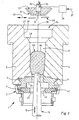
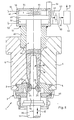
- Fig. 9 corresponds to the extent of Fig. 5, as in Fig. 9 also the parison 18 in the still closed preform 1 has been pressed. It is this around a parison 18, from which a so-called Wide-mouth glass with a relatively large mouth diameter becomes.
- a non-slit block shape 72 is used instead of the longitudinally divided preform halves 5, 6 in previous figures 9.
- the block form 72 can be raised and lowered by one in the directions of the double arrow 73 not shown, known lifting mechanism.
- To the Closing the preform 1 according to FIG. 9 first becomes the mouth tool 2 closed. Then the block mold 72 is raised until a radial Annular surface 75 of the block shape to a corresponding annular surface 76 of the Muzzle tool 2 has created.
- the tumbler ring 74 prevents the closed Muzzle tool 2 during the pressing process in undesirable Way opens.
- the pressing member 44 is in a bottom opening 77 of the block shape 72 analogous to FIG. 7 or 8.
- the cylinder 50 is in this case, e.g. attached to the bottom of the block mold 72 by a weld or screw.
- the pressing process takes place in two stages, namely with one 4 and a finishing press according to FIG. 5.
- the block shape 72 could also follow with the recess 17 be arranged below. Then the lot is inserted through the bottom opening 77.
- the bottom opening 77 can for this purpose according to the funnel-shaped loading opening 26 may be formed in Fig. 3. Should have to load the piston-cylinder unit 48, the pressing element 44 and the displacement sensor 57 in similarly removed from the block mold 72 as in Fig. 3 from the closed preform halves 5, 6.
Landscapes
- Engineering & Computer Science (AREA)
- Chemical & Material Sciences (AREA)
- Manufacturing & Machinery (AREA)
- Materials Engineering (AREA)
- Organic Chemistry (AREA)
- Mechanical Engineering (AREA)
- Physics & Mathematics (AREA)
- Geometry (AREA)
- Blow-Moulding Or Thermoforming Of Plastics Or The Like (AREA)
- Auxiliary Devices For And Details Of Packaging Control (AREA)
- Treatments For Attaching Organic Compounds To Fibrous Goods (AREA)
- Press Drives And Press Lines (AREA)
Description
Claims (11)
- Verfahren zur Herstellung eines Külbels (18) durch Pressen in einer Vorform (1) einer Preß-Blas-Glasformmaschine, mit folgenden Schritten:gekennzeichnet durch folgende Schritte:(a) Aus einem Speiser (32) wird ein Posten (38) schmelzflüssigen Glases von oben durch eine Ladeöffnung (26) hindurch in eine Ausnehmung (17) der Vorform (1) eingebracht, während die Vorform (1) eine Mündungsform mit einem geschlossenen, längsgeteilten, eine Mündung (19) des Külbels (18) formenden Mündungswerkzeug (2) aufweist,(b) ein Preßstempel (10) wird durch einen mittigen Durchlaß (42) der Mündungsform hindurch in den Posten (38) hineingepreßt, bis er in einer Arbeitsendstellung (Fig.4;9) an der Mündungsform anliegt, wobei das Külbel (18) bis zu einer teilweisen Füllung der Ausnehmung (17) mit schmelzflüssigem Glas vorgepreßt wird,(c) gleichzeitig mit oder im Anschluß an Schritt (b) wird mit einem einen Teil der Ausnehmung (17) begrenzenden Preßelement (44) Druck auf einen Boden (66) des gemäß Schritt (b) vorgepreßten Külbels (18) ausgeübt, bis die Ausnehmung (17) vollständig mit schmelzflüssigem Glas gefüllt und das Külbel (18) fertiggepreßt ist, und(d) wenn in der Arbeitsendstellung (Fig. 4;9) des Preßstempels (10) die Ausnehmung (17) vollständig mit schmelzflüssigem Glas gefüllt und das Külbel (18) geformt ist, werden einerseits das Preßelement (44) und alle Bestandteile der Vorform (1) mit Ausnahme des weiterhin geschlossenen Mündungswerkzeugs (2) so weit entfernt, daß das weiterhin geschlossene Mündungswerkzeug (2) mit dem durch das Mündungswerkzeug (2) an der Mündung (19) gehaltenen Külbel (18) in eine Fertigformstation der Glasformmaschine übergeben werden kann, und wird andererseits der Preßstempel (10) aus dem Külbel (18) heraus in eine Übergabeendstellung (Fig. 6) zurückbewegt,(A) im Schritt (b) wird der Preßstempel (10) in seine Arbeitsendstellung (Fig. 4;9) bis zur Anlage (24) an dem Mündungswerkzeug (2) bewegt, und(B) ein axial äußerer Dichtungsrand (20) der Mündung (19) des Külbels (18) wird vollständig durch den Preßstempel (10) geformt.
- Verfahren nach Anspruch 1,
dadurch gekennzeichnet, daß das Glas schon im Schritt (A) in Berührung mit dem Preßelement (44) tritt,
und daß das Preßelement (44) durch das Glas aus der Ausnehmung (17) herausbewegt wird. - Verfahren nach Anspruch 1 oder 2,
dadurch gekennzeichnet, daß die Vorform (1) längsgeteilte Vorformhälften (5,6) aufweist,
daß der Posten (38) durch die in einem Boden der geschlossenen Vorformhälften (5,6) ausgebildete Ladeöffnung (26) hindurch eingebracht wird,
und daß die Ladeöffnung (26) nach dem Laden durch das Preßelement (44) geschlossen wird. - Verfahren nach einem der Ansprüche 1 bis 3,
dadurch gekennzeichnet, daß die im Schritt (B) sich ergebende maximale Eindringtiefe des Preßelements (44) in die Ausnehmung (17) durch eine Wegmessung (57) des Preßelements (44) relativ zu der Vorform (1) festgestellt wird,
und daß die Wegmessung (57) zur Steuerung und/oder Regelung der Masse der den Speiser (32) verlassenden Posten (38) verwendet wird. - Vorrichtung zur Herstellung eines Külbels (18) durch Pressen in einer Vorform (1) einer Preß-Blas-Glasformmaschine,
wobei aus einem Speiser (32) ein Posten (38) schmelzflüssigen Glases von oben durch eine Ladeöffnung (26) hindurch in eine Ausnehmung (17) der Vorform (1) einbringbar ist, während die Vorform (1) eine Mündungsform mit einem geschlossenen, längsgeteilten, eine Mündung (19) des Külbels (18) formenden Mündungswerkzeug (2) aufweist, welches Mündungswerkzeug geöffnet und wieder geschlossen werden kann,
mit einem durch einen mittigen Durchlaß (42) der Mündungsform hindurch bis in eine Arbeitsendstellung (Fig. 4;9) in Anlage an der Mündungsform zum Vorpressen des Külbels (18) in den Posten (38) preßbaren und nach Formung des Külbels (18) aus dem Külbel (18) herausziehbaren Preßstempel (10),
und mit einem einen Teil der Ausnehmung (17) begrenzenden, relativ zu der Vorform (1) bewegbaren Preßelement (44),
wobei mit dem Preßelement (44) Druck auf einen Boden (66) des vorgepreßten Külbels (18) ausübbar ist, bis die Ausnehmung (17) vollständig mit schmelzflüssigem Glas gefüllt und das Külbel (18) fertiggepreßt ist,
dadurch gekennzeichnet, daß der Preßstempel (10) in seiner Arbeitsendstellung (Fig. 4;9) an dem Mündungswerkzeug (2) anliegt (24),
und daß der Preßstempel so geformt ist, daß ein axial äußerer Dichtungsrand (20) der Mündung (19) des Külbels (18) vollständig durch den Preßstempel (10) formbar ist. - Vorrichtung nach Anspruch 5,
dadurch gekennzeichnet, daß die Vorform (1) längsgeteilte Vorformhälften (5,6) aufweist,
daß die Ladeöffnung (26) in einem Boden der geschlossenen Vorformhälften (5,6) ausgebildet ist,
und daß die Ladeöffnung (26) nach dem Laden durch das Preßelement (44) schließbar ist. - Vorrichtung nach Anspruch 5,
dadurch gekennzeichnet, daß die Vorform (1) eine nicht längsgeteilte Blockform (72) aufweist,
daß das Preßelement (44) in einer unteren Bodenöffnung (77) der Blockform (72) verschiebbar gelagert ist,
daß sich an die Ladeöffnung (26) der Blockform (72) nach oben hin das geschlossene Mündungswerkzeug (2) anschließt,
und daß an dem geschlossenen Mündungswerkzeug (2) radial außen ein Zuhaltering (74) der Blockform (72) anliegt. - Vorrichtung nach einem der Ansprüche 5 bis 7,
dadurch gekennzeichnet, daß sich an einen Fuß (22) des Preßstempels (10) ein breiter als der Preßstempel (10) ausgebildeter Schaft (16) anschließt,
und daß in einer ringförmigen Stirnfläche (23) des Schafts (16), angrenzend an den Fuß (22), eine ringförmige Ausnehmung (21) zur Formung des vollständigen axial äußeren Dichtungsrandes (20) der Mündung (19) des Külbels (18) ausgebildet ist. - Vorrichtung nach Anspruch 8,
dadurch gekennzeichnet, daß die Stirnfläche (23) zur Definition der Arbeitsendstellung (Fig. 4;9) des Preßstempels (10) an einer Anschlagfläche (24) des geschlossenen Mündungswerkzeugs (2) anliegt. - Vorrichtung nach einem der Ansprüche 5 bis 9,
dadurch gekennzeichnet, daß sich an einen Fuß (22) des Preßstempels (10) ein zylindrischer Schaft (16) anschließt,
und daß der Schaft (16) auf einem letzten Teil des Weges des Preßstempels (10) bis in seine Arbeitsendstellung (Fig. 4;9) in einen relativ zu der Vorform (1) festen Zentrierring (41) eintaucht und durch den Zentrierring (41) in radialer Richtung zentriert und geführt ist. - Vorrichtung nach Anspruch 10,
dadurch gekennzeichnet, daß der Zentrierring (41) nicht längsgeteilt ist, und daß der Zentrierring (41) radial außen in einer Haltenut (7) des Mündungswerkzeugs (2) gehalten ist.
Applications Claiming Priority (3)
| Application Number | Priority Date | Filing Date | Title |
|---|---|---|---|
| DE19935866 | 1999-07-30 | ||
| DE19935866A DE19935866C1 (de) | 1999-07-30 | 1999-07-30 | Verfahren und Vorrichtung zum Pressen eines Külbels |
| PCT/EP2000/007088 WO2001009049A1 (de) | 1999-07-30 | 2000-07-25 | Verfahren und vorrichtung zum pressen eines külbels |
Publications (2)
| Publication Number | Publication Date |
|---|---|
| EP1129039A1 EP1129039A1 (de) | 2001-09-05 |
| EP1129039B1 true EP1129039B1 (de) | 2004-03-17 |
Family
ID=7916612
Family Applications (1)
| Application Number | Title | Priority Date | Filing Date |
|---|---|---|---|
| EP00947993A Expired - Lifetime EP1129039B1 (de) | 1999-07-30 | 2000-07-25 | Verfahren und vorrichtung zum pressen eines külbels |
Country Status (8)
| Country | Link |
|---|---|
| US (1) | US6698241B1 (de) |
| EP (1) | EP1129039B1 (de) |
| JP (1) | JP2003506302A (de) |
| AT (1) | ATE261917T1 (de) |
| AU (1) | AU6159500A (de) |
| CA (1) | CA2345142A1 (de) |
| DE (2) | DE19935866C1 (de) |
| WO (1) | WO2001009049A1 (de) |
Cited By (1)
| Publication number | Priority date | Publication date | Assignee | Title |
|---|---|---|---|---|
| WO2023020667A1 (de) | 2021-08-20 | 2023-02-23 | Gerresheimer Glas Gmbh | VORFORMBODEN-PREß-SYSTEM ZUR AUSBILDUNG EINES GRATFREIEN MÜNDUNGSEINGANGS EINES ZU FERTIGENDEN GLASBEHÄLTERS SOWIE EIN VERFAHREN ZUR HERSTELLUNG EINES KÜLBELS VERMITTELS DESSEN |
Families Citing this family (12)
| Publication number | Priority date | Publication date | Assignee | Title |
|---|---|---|---|---|
| TWI245747B (en) * | 2004-07-30 | 2005-12-21 | Asia Optical Co Inc | Glass molding forming device capable of positioning glass material, supporting lens |
| TW200606111A (en) * | 2004-08-10 | 2006-02-16 | Asia Optical Co Inc | Continuous glass molding system |
| TWI245746B (en) * | 2004-08-10 | 2005-12-21 | Asia Optical Co Inc | Continuous type glass molding forming system |
| DE102009008723B4 (de) * | 2009-02-06 | 2011-07-07 | Schott Ag, 55122 | Verfahren zur Herstellung eines pharmazeutischen Behälters aus der Schmelze und Behälter |
| JP4786733B2 (ja) * | 2009-07-24 | 2011-10-05 | 東洋ガラス株式会社 | ガイドリング及びガラスびん |
| JP4851571B2 (ja) * | 2009-09-09 | 2012-01-11 | 東洋ガラス株式会社 | ガイドリング及びガラスびん |
| CN103402931B (zh) * | 2011-03-10 | 2015-11-25 | 东洋玻璃株式会社 | 玻璃瓶成型机 |
| WO2012124079A1 (ja) * | 2011-03-16 | 2012-09-20 | 東洋ガラス株式会社 | ガラスびんの成形方法 |
| CN102557390B (zh) * | 2012-01-16 | 2015-12-16 | 戴东浦 | 开口容器模具及其生产出的开口容器 |
| US11524914B1 (en) * | 2019-08-29 | 2022-12-13 | Owens-Brockway Glass Container Inc. | Method and apparatus for forming a parison |
| US11365144B1 (en) * | 2019-08-29 | 2022-06-21 | Owens-Brockway Glass Container Inc. | Method and apparatus for forming a parison |
| IT202200003137A1 (it) | 2022-02-21 | 2023-08-21 | Vetreria Di Borgonovo S P A | Procedimento per lo stampaggio e la produzione di vetro cavo, in particolare di un tappo di vetro con una protuberanza sagomata, e corrispondente apparecchiatura di stampaggio |
Family Cites Families (12)
| Publication number | Priority date | Publication date | Assignee | Title |
|---|---|---|---|---|
| US424524A (en) * | 1890-04-01 | Mold foe making glass bottles or like articles | ||
| US781539A (en) * | 1904-02-08 | 1905-01-31 | George A Marsh | Machine for making hollow glassware. |
| US1670821A (en) * | 1925-06-19 | 1928-05-22 | Salem Glass Works | Nonpull plunger for bottle-making machines |
| US4336050A (en) * | 1980-01-17 | 1982-06-22 | John D. Northrup, Jr. | Method for manufacturing glass bottles |
| DE3232288C1 (de) * | 1982-08-31 | 1983-10-20 | Fa. Hermann Heye, 3063 Obernkirchen | Verfahren und Vorrichtung zum Pressen eines Glaskuelbels |
| US4411681A (en) | 1983-01-14 | 1983-10-25 | Ruth B. Northup | Method and apparatus for manufacturing glass bottles |
| US4551163A (en) * | 1984-06-04 | 1985-11-05 | Emhart Industries, Inc. | Electronic glass feeder plunger operating mechanism |
| GB2159813B (en) * | 1984-06-06 | 1987-12-31 | Emhart Ind | Forming a gob of molten glass into a parison |
| US4662928A (en) * | 1985-11-04 | 1987-05-05 | Owens-Illinois, Inc. | Apparatus for forming a glass bottle finish |
| US5236485A (en) * | 1986-09-30 | 1993-08-17 | Manfred Leweringhause | Process and device for shaping a gob |
| US4867778A (en) * | 1988-02-05 | 1989-09-19 | Emhart Industries, Inc. | Individual section glass forming machine |
| GB9121367D0 (en) * | 1991-10-09 | 1991-11-20 | Emhart Glass Mach Invest | Hall sensor movement detection device |
-
1999
- 1999-07-30 DE DE19935866A patent/DE19935866C1/de not_active Expired - Fee Related
-
2000
- 2000-07-25 EP EP00947993A patent/EP1129039B1/de not_active Expired - Lifetime
- 2000-07-25 JP JP2001514255A patent/JP2003506302A/ja not_active Ceased
- 2000-07-25 CA CA002345142A patent/CA2345142A1/en not_active Abandoned
- 2000-07-25 AU AU61595/00A patent/AU6159500A/en not_active Abandoned
- 2000-07-25 AT AT00947993T patent/ATE261917T1/de not_active IP Right Cessation
- 2000-07-25 US US09/786,668 patent/US6698241B1/en not_active Expired - Fee Related
- 2000-07-25 WO PCT/EP2000/007088 patent/WO2001009049A1/de not_active Ceased
- 2000-07-25 DE DE50005678T patent/DE50005678D1/de not_active Expired - Fee Related
Cited By (2)
| Publication number | Priority date | Publication date | Assignee | Title |
|---|---|---|---|---|
| WO2023020667A1 (de) | 2021-08-20 | 2023-02-23 | Gerresheimer Glas Gmbh | VORFORMBODEN-PREß-SYSTEM ZUR AUSBILDUNG EINES GRATFREIEN MÜNDUNGSEINGANGS EINES ZU FERTIGENDEN GLASBEHÄLTERS SOWIE EIN VERFAHREN ZUR HERSTELLUNG EINES KÜLBELS VERMITTELS DESSEN |
| DE102021004257A1 (de) | 2021-08-20 | 2023-02-23 | Gerresheimer Glas Gmbh | Vorformboden-Preß-System zur Ausbildung eines gratfreien Mündungseingangs eines zu fertigenden Glasbehälters sowie ein Verfahren zur Herstellung eines Kübels vermittels dessen |
Also Published As
| Publication number | Publication date |
|---|---|
| US6698241B1 (en) | 2004-03-02 |
| JP2003506302A (ja) | 2003-02-18 |
| AU6159500A (en) | 2001-02-19 |
| EP1129039A1 (de) | 2001-09-05 |
| WO2001009049A1 (de) | 2001-02-08 |
| CA2345142A1 (en) | 2001-02-08 |
| ATE261917T1 (de) | 2004-04-15 |
| DE50005678D1 (de) | 2004-04-22 |
| DE19935866C1 (de) | 2000-11-23 |
Similar Documents
| Publication | Publication Date | Title |
|---|---|---|
| EP1129039B1 (de) | Verfahren und vorrichtung zum pressen eines külbels | |
| DE2453038B2 (de) | Maschine des is-typs zur herstellung von hohlen glasgegenstaenden nach dem press-blasverfahren | |
| DE2809178C3 (de) | IS-Glasformmaschine | |
| DE2611244A1 (de) | Verfahren und vorrichtung zum zweistufigen blasformen | |
| DE2458233B2 (de) | Vorrichtung zum herstellen von glaesern nach dem kuelbeldrehverfahren | |
| DE60310531T2 (de) | Vorrichtung und Verfahren zum Pressformen von Kunststoff-Behältern | |
| DE2732978A1 (de) | Verfahren und vorrichtung zur herstellung hohler gegenstaende aus aushaertbaren, plastifizierten stoffen durch blasgiessen | |
| DE2537185A1 (de) | Verfahren und vorrichtung fuer die herstellung von kunststoffgegenstaenden | |
| EP4387939B1 (de) | Vorformboden-press-system zur ausbildung eines gratfreien mündungseingangs eines zu fertigenden glasbehälters sowie ein verfahren zur herstellung eines külbels vermittels dessen | |
| EP0102001B1 (de) | Verfahren und Vorrichtung zum Pressen eines Glaskülbels | |
| DE69516229T2 (de) | Verbesserungen beim Herstellen von Glascontainern | |
| DE3334957A1 (de) | Verfahren und vorrichtung zur herstellung von kuelbeln | |
| EP4186876B1 (de) | Is-maschine zur herstellung von glasbehältern und verfahren zum betreiben einer solchen is-maschine | |
| EP1565410B1 (de) | Anlage zur herstellung von glasstopfen zum verschluss von flaschen | |
| EP3197655A1 (de) | Verfahren und vorrichtung zur herstellung einer optimierten halskontur an preformen | |
| EP1377424B1 (de) | Verfahren zum ausformen von thermoplastischem kunststoff | |
| DE3341228C2 (de) | Formwerkzeug für einen Behälter-Kopfteil aus Kunststoff | |
| DE19528695A1 (de) | Verfahren und Vorrichtung zum Herstellen von Hohlkörpern aus thermoplastischem Kunststoff | |
| EP1423341B1 (de) | Verfahren und fertigformstation zum fertigblasen eines glasbehälters | |
| EP1960180A1 (de) | Nachbehandlungsverfahren sowie vorrichtung hierfür | |
| DE19647536C1 (de) | Vorformstation einer Preß-Blase-Glasformmaschine | |
| DE3025333A1 (de) | Vorrichtung zum formen von kuelbeln zur herstellung von enghalsigen glaswaren nach dem press-blas-verfahren | |
| DE635507C (de) | Verfahren und Vorrichtung zur Herstellung von Glashohlkoerpern | |
| DE1471904B2 (de) | Vorrichtung zum Formen von Glas | |
| DE2010443C (de) | Vorrichtung zum Formen von Kulbeln zur Herstellung von enghalsigen Glas waren nach dem Preß Blas Verfahren |
Legal Events
| Date | Code | Title | Description |
|---|---|---|---|
| PUAI | Public reference made under article 153(3) epc to a published international application that has entered the european phase |
Free format text: ORIGINAL CODE: 0009012 |
|
| 17P | Request for examination filed |
Effective date: 20010110 |
|
| AK | Designated contracting states |
Kind code of ref document: A1 Designated state(s): AT BE CH CY DE DK ES FI FR GB GR IE IT LI LU MC NL PT SE |
|
| AX | Request for extension of the european patent |
Free format text: AL;LT;LV;MK;RO;SI |
|
| RAP1 | Party data changed (applicant data changed or rights of an application transferred) |
Owner name: HEYE INTERNATIONAL GMBH |
|
| GRAP | Despatch of communication of intention to grant a patent |
Free format text: ORIGINAL CODE: EPIDOSNIGR1 |
|
| GRAS | Grant fee paid |
Free format text: ORIGINAL CODE: EPIDOSNIGR3 |
|
| GRAA | (expected) grant |
Free format text: ORIGINAL CODE: 0009210 |
|
| AK | Designated contracting states |
Kind code of ref document: B1 Designated state(s): AT BE CH CY DE DK ES FI FR GB GR IE IT LI LU MC NL PT SE |
|
| PG25 | Lapsed in a contracting state [announced via postgrant information from national office to epo] |
Ref country code: IE Free format text: LAPSE BECAUSE OF FAILURE TO SUBMIT A TRANSLATION OF THE DESCRIPTION OR TO PAY THE FEE WITHIN THE PRESCRIBED TIME-LIMIT Effective date: 20040317 Ref country code: FI Free format text: LAPSE BECAUSE OF FAILURE TO SUBMIT A TRANSLATION OF THE DESCRIPTION OR TO PAY THE FEE WITHIN THE PRESCRIBED TIME-LIMIT Effective date: 20040317 Ref country code: NL Free format text: LAPSE BECAUSE OF FAILURE TO SUBMIT A TRANSLATION OF THE DESCRIPTION OR TO PAY THE FEE WITHIN THE PRESCRIBED TIME-LIMIT Effective date: 20040317 Ref country code: CY Free format text: LAPSE BECAUSE OF FAILURE TO SUBMIT A TRANSLATION OF THE DESCRIPTION OR TO PAY THE FEE WITHIN THE PRESCRIBED TIME-LIMIT Effective date: 20040317 |
|
| REG | Reference to a national code |
Ref country code: GB Ref legal event code: FG4D Free format text: NOT ENGLISH |
|
| REG | Reference to a national code |
Ref country code: CH Ref legal event code: EP Ref country code: CH Ref legal event code: NV Representative=s name: A. BRAUN, BRAUN, HERITIER, ESCHMANN AG PATENTANWAE |
|
| REG | Reference to a national code |
Ref country code: IE Ref legal event code: FG4D Free format text: GERMAN |
|
| REF | Corresponds to: |
Ref document number: 50005678 Country of ref document: DE Date of ref document: 20040422 Kind code of ref document: P |
|
| GBT | Gb: translation of ep patent filed (gb section 77(6)(a)/1977) |
Effective date: 20040414 |
|
| PG25 | Lapsed in a contracting state [announced via postgrant information from national office to epo] |
Ref country code: GR Free format text: LAPSE BECAUSE OF FAILURE TO SUBMIT A TRANSLATION OF THE DESCRIPTION OR TO PAY THE FEE WITHIN THE PRESCRIBED TIME-LIMIT Effective date: 20040617 Ref country code: DK Free format text: LAPSE BECAUSE OF FAILURE TO SUBMIT A TRANSLATION OF THE DESCRIPTION OR TO PAY THE FEE WITHIN THE PRESCRIBED TIME-LIMIT Effective date: 20040617 |
|
| PG25 | Lapsed in a contracting state [announced via postgrant information from national office to epo] |
Ref country code: ES Free format text: LAPSE BECAUSE OF FAILURE TO SUBMIT A TRANSLATION OF THE DESCRIPTION OR TO PAY THE FEE WITHIN THE PRESCRIBED TIME-LIMIT Effective date: 20040628 |
|
| REG | Reference to a national code |
Ref country code: SE Ref legal event code: TRGR |
|
| PG25 | Lapsed in a contracting state [announced via postgrant information from national office to epo] |
Ref country code: AT Free format text: LAPSE BECAUSE OF NON-PAYMENT OF DUE FEES Effective date: 20040725 Ref country code: LU Free format text: LAPSE BECAUSE OF NON-PAYMENT OF DUE FEES Effective date: 20040725 |
|
| PG25 | Lapsed in a contracting state [announced via postgrant information from national office to epo] |
Ref country code: MC Free format text: LAPSE BECAUSE OF NON-PAYMENT OF DUE FEES Effective date: 20040731 Ref country code: BE Free format text: LAPSE BECAUSE OF NON-PAYMENT OF DUE FEES Effective date: 20040731 |
|
| LTIE | Lt: invalidation of european patent or patent extension |
Effective date: 20040317 |
|
| RAP2 | Party data changed (patent owner data changed or rights of a patent transferred) |
Owner name: HEYE INTERNATIONAL GMBH |
|
| NLV1 | Nl: lapsed or annulled due to failure to fulfill the requirements of art. 29p and 29m of the patents act | ||
| REG | Reference to a national code |
Ref country code: IE Ref legal event code: FD4D |
|
| ET | Fr: translation filed | ||
| PLBE | No opposition filed within time limit |
Free format text: ORIGINAL CODE: 0009261 |
|
| STAA | Information on the status of an ep patent application or granted ep patent |
Free format text: STATUS: NO OPPOSITION FILED WITHIN TIME LIMIT |
|
| BERE | Be: lapsed |
Owner name: *HEYE INTERNATIONAL G.M.B.H. Effective date: 20040731 |
|
| 26N | No opposition filed |
Effective date: 20041220 |
|
| PGFP | Annual fee paid to national office [announced via postgrant information from national office to epo] |
Ref country code: DE Payment date: 20070803 Year of fee payment: 8 |
|
| PGFP | Annual fee paid to national office [announced via postgrant information from national office to epo] |
Ref country code: CH Payment date: 20070724 Year of fee payment: 8 |
|
| BERE | Be: lapsed |
Owner name: *HEYE INTERNATIONAL G.M.B.H. Effective date: 20040731 |
|
| PG25 | Lapsed in a contracting state [announced via postgrant information from national office to epo] |
Ref country code: PT Free format text: LAPSE BECAUSE OF NON-PAYMENT OF DUE FEES Effective date: 20040817 |
|
| PGFP | Annual fee paid to national office [announced via postgrant information from national office to epo] |
Ref country code: GB Payment date: 20070730 Year of fee payment: 8 |
|
| PGFP | Annual fee paid to national office [announced via postgrant information from national office to epo] |
Ref country code: IT Payment date: 20070726 Year of fee payment: 8 Ref country code: SE Payment date: 20070724 Year of fee payment: 8 |
|
| PGFP | Annual fee paid to national office [announced via postgrant information from national office to epo] |
Ref country code: FR Payment date: 20070718 Year of fee payment: 8 |
|
| REG | Reference to a national code |
Ref country code: CH Ref legal event code: PFA Owner name: HEYE INTERNATIONAL GMBH Free format text: HEYE INTERNATIONAL GMBH#AM ZIEGELEIWEG 3#31683 OBERNKIRCHEN (DE) -TRANSFER TO- HEYE INTERNATIONAL GMBH#AM ZIEGELEIWEG 3#31683 OBERNKIRCHEN (DE) |
|
| REG | Reference to a national code |
Ref country code: CH Ref legal event code: PL |
|
| EUG | Se: european patent has lapsed | ||
| GBPC | Gb: european patent ceased through non-payment of renewal fee |
Effective date: 20080725 |
|
| PG25 | Lapsed in a contracting state [announced via postgrant information from national office to epo] |
Ref country code: DE Free format text: LAPSE BECAUSE OF NON-PAYMENT OF DUE FEES Effective date: 20090203 |
|
| REG | Reference to a national code |
Ref country code: FR Ref legal event code: ST Effective date: 20090331 |
|
| PG25 | Lapsed in a contracting state [announced via postgrant information from national office to epo] |
Ref country code: GB Free format text: LAPSE BECAUSE OF NON-PAYMENT OF DUE FEES Effective date: 20080725 Ref country code: LI Free format text: LAPSE BECAUSE OF NON-PAYMENT OF DUE FEES Effective date: 20080731 Ref country code: CH Free format text: LAPSE BECAUSE OF NON-PAYMENT OF DUE FEES Effective date: 20080731 |
|
| PG25 | Lapsed in a contracting state [announced via postgrant information from national office to epo] |
Ref country code: IT Free format text: LAPSE BECAUSE OF NON-PAYMENT OF DUE FEES Effective date: 20080725 Ref country code: FR Free format text: LAPSE BECAUSE OF NON-PAYMENT OF DUE FEES Effective date: 20080731 |
|
| PG25 | Lapsed in a contracting state [announced via postgrant information from national office to epo] |
Ref country code: SE Free format text: LAPSE BECAUSE OF NON-PAYMENT OF DUE FEES Effective date: 20080726 |