EP1129272B1 - Verfahren und vorrichtung zur abstandsbedienung einer rohrausgangshülse - Google Patents
Verfahren und vorrichtung zur abstandsbedienung einer rohrausgangshülse Download PDFInfo
- Publication number
- EP1129272B1 EP1129272B1 EP99961530A EP99961530A EP1129272B1 EP 1129272 B1 EP1129272 B1 EP 1129272B1 EP 99961530 A EP99961530 A EP 99961530A EP 99961530 A EP99961530 A EP 99961530A EP 1129272 B1 EP1129272 B1 EP 1129272B1
- Authority
- EP
- European Patent Office
- Prior art keywords
- sleeve
- body portion
- window
- tubing
- assembly according
- Prior art date
- Legal status (The legal status is an assumption and is not a legal conclusion. Google has not performed a legal analysis and makes no representation as to the accuracy of the status listed.)
- Expired - Lifetime
Links
- 238000000034 method Methods 0.000 title claims description 11
- 230000005291 magnetic effect Effects 0.000 claims description 18
- 238000006073 displacement reaction Methods 0.000 claims description 11
- 239000012530 fluid Substances 0.000 claims description 8
- 238000004891 communication Methods 0.000 claims description 6
- 230000004907 flux Effects 0.000 claims description 3
- 238000004519 manufacturing process Methods 0.000 description 11
- 230000015572 biosynthetic process Effects 0.000 description 7
- 238000005755 formation reaction Methods 0.000 description 7
- 229930195733 hydrocarbon Natural products 0.000 description 6
- 239000004215 Carbon black (E152) Substances 0.000 description 5
- 238000012423 maintenance Methods 0.000 description 5
- 239000004020 conductor Substances 0.000 description 4
- 150000002430 hydrocarbons Chemical class 0.000 description 4
- 238000005553 drilling Methods 0.000 description 3
- 238000011084 recovery Methods 0.000 description 3
- 150000003839 salts Chemical class 0.000 description 3
- 229910000831 Steel Inorganic materials 0.000 description 2
- 230000008901 benefit Effects 0.000 description 2
- 230000005540 biological transmission Effects 0.000 description 2
- 239000004568 cement Substances 0.000 description 2
- 239000007789 gas Substances 0.000 description 2
- 125000001183 hydrocarbyl group Chemical group 0.000 description 2
- 230000003993 interaction Effects 0.000 description 2
- 239000007788 liquid Substances 0.000 description 2
- 239000000463 material Substances 0.000 description 2
- 238000012986 modification Methods 0.000 description 2
- 230000004048 modification Effects 0.000 description 2
- 239000010959 steel Substances 0.000 description 2
- 230000008859 change Effects 0.000 description 1
- 238000007796 conventional method Methods 0.000 description 1
- 230000001419 dependent effect Effects 0.000 description 1
- 230000000694 effects Effects 0.000 description 1
- 239000003302 ferromagnetic material Substances 0.000 description 1
- 238000011010 flushing procedure Methods 0.000 description 1
- 238000002955 isolation Methods 0.000 description 1
- 230000013011 mating Effects 0.000 description 1
- 230000007246 mechanism Effects 0.000 description 1
- 229910001092 metal group alloy Inorganic materials 0.000 description 1
- 210000002445 nipple Anatomy 0.000 description 1
- 239000004033 plastic Substances 0.000 description 1
- 229920003023 plastic Polymers 0.000 description 1
- 238000003825 pressing Methods 0.000 description 1
- 230000004044 response Effects 0.000 description 1
- 239000007787 solid Substances 0.000 description 1
- 238000011282 treatment Methods 0.000 description 1
Images

Classifications
-
- E—FIXED CONSTRUCTIONS
- E21—EARTH OR ROCK DRILLING; MINING
- E21B—EARTH OR ROCK DRILLING; OBTAINING OIL, GAS, WATER, SOLUBLE OR MELTABLE MATERIALS OR A SLURRY OF MINERALS FROM WELLS
- E21B43/00—Methods or apparatus for obtaining oil, gas, water, soluble or meltable materials or a slurry of minerals from wells
- E21B43/30—Specific pattern of wells, e.g. optimising the spacing of wells
- E21B43/305—Specific pattern of wells, e.g. optimising the spacing of wells comprising at least one inclined or horizontal well
-
- E—FIXED CONSTRUCTIONS
- E21—EARTH OR ROCK DRILLING; MINING
- E21B—EARTH OR ROCK DRILLING; OBTAINING OIL, GAS, WATER, SOLUBLE OR MELTABLE MATERIALS OR A SLURRY OF MINERALS FROM WELLS
- E21B17/00—Drilling rods or pipes; Flexible drill strings; Kellies; Drill collars; Sucker rods; Cables; Casings; Tubings
Definitions
- the present invention relates generally to subsurface well completion equipment, and in particular to a remotely controllable exit sleeve for multilateral wellbores.
- Hydrocarbon recovery volume from a vertically-drilled well can be increased by drilling additional wellbores from that same well.
- the fluid recovery rate and the well's economic life can be increased by drilling a horizontal, or lateral, interval from a main wellbore into one or more formations.
- Still further increases in recovery and well life can be attained by drilling multiple horizontal intervals into multiple hydrocarbon-bearing formations.
- Oil and gas production from hydrocarbon-bearing geological formations can yield high levels of salt and other elements that can seriously hamper the well production.
- the well casing extends down into the formation, and includes a plurality of perforations that extend laterally into the formation to permit the hydrocarbons to flow into the main wellbore.
- Production tubing, which extends through the casing, and packers are then used to conduct the hydrocarbon out of the well.
- Salts and other elements from the formation tend to deposit in the production tubing and, more significantly, in the perforations that extend from the casing into the formation. Over time, deposits can accumulate in the perforation walls and along the flow path, significantly reducing the perforation diameters and in turn, reduce the production flow from the well. Also, over the life of the well, its production rate and the amounts of undesirable elements present in the hydrocarbon production varies.
- Deposits of salt and other water-soluble elements can be removed and/or prevented by treating the well, such as by flushing the production tubing with solutions in which the deposits are soluble, or by injecting the solutions into the production tubing to dislodge the deposits.
- US 5,730,224 describes a diverter mechanism for controlling access to a lateral wellbore.
- Sliding sleeves have been installed in multilateral wells adjacent the lateral bores, but manipulation of these units have been time consuming and added to the maintenance expense of a well.
- a coiled-tubing tool had to make a well trip to raise the side door.
- the maintenance tool was lowered into the well to access the lateral wellbore so that well maintenance can be done.
- the position of a side door has not been readily discemable from the surface, and must be determined from records concerning the configuration of the well, or an exploratory trip that may simply determine that the side door was in the necessary position.
- US 5,666,050 relates to a well apparatus for detecting the position of a moving element in a well.
- a downhole tubing exit-window assembly comprising: a tubular body portion defining a side port that is sufficiently-sized to allow a well tool to pass therethrough; and a sleeve adjacent to said tubular body portion and reciprocatingly coupled about a longitudinal axis of said tubular body portion, characterised in that, said sleeve is responsive to a remote command such that, in response to the remote command, a sleeve window defined in a side of said sleeve can be substantially-aligned with said side port in an open relation such that a well tool can pass through said substantially-aligned sleeve window and side port, said remote command being transmitted from a location remote from the sleeve to the sleeve.
- a method of selectively accessing a lateral wellbore of a multilateral well comprising the steps of: providing a remote-controlled tubing exit sleeve in the multilateral well, the tubing exit sleeve having a body portion defining a side port and a reciprocating side-window sleeve received about an axis of the body portion and responsive to a remote command; and characterised by remotely positioning the side-window sleeve with respect to the body portion such that a well tool can access the lateral wellbore by transmitting to the remote controlled tubing sleeve a remote command that is transmitted from a location remote from the tubing sleeve to the tubing sleeve.
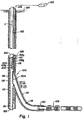
- FIGURE 1 is a cross-sectional schematic view of a remotely-controlled tubing exit sleeve of the present invention deployed in a multilateral well 100 having a main wellbore 110 and at least one lateral wellbore 112. Also shown is a production assembly 108 extending into the lateral wellbore 112.
- the main wellbore 110 and the lateral wellbore 112 have been drilled into the earth 114, which is generally referred to as "material surrounding the wellbores.”
- a main casing 116 is set into the main wellbore 110 with cement 117, using methods known to those skilled in the art.
- the lateral wellbore 112 is formed using methods known in the art, such as that disclosed in U.S. Patent No. 5,735,3 50 issued April 7, 1998, to Longbottom et al., which is incorporated herein by reference for all purposes.
- the lateral wellbore has a lateral lining 118 set into the lateral wellbore 112 with lateral liner cement 120.
- the tubing exit sleeve 200 has a tubing body 202. Received within the tubing body 202 is an exit-window sleeve 204. The exit-window sleeve 204 is adjacent to the tubing body 202 and is in a substantially-coaxial relation with respect to the tubing body 202.
- the exit window sleeve 204 is in a closed position to block access from the inner bore of the tubing string 122 to the inner bore of the lateral liner 118.
- the exit-window sleeve 204 is remote-controlled from the surface 124 by a microcontroller-based control system 126.
- the control system 126 is coupled with an electro-hydraulic downhole completion system that can be manipulated to modify the flow profile of the multilateral well 100.
- a downhole communication and power cable 128 couples the microcontroller-based system 126 to the tubing exit sleeve 200 such that the tubing exit sleeve 200 is responsive to commands transmitted from the control system 126.
- the communication and power cable 128 is a dual-redundant umbilical line, each line having at least a return 128 a and input hydraulic line 128 b , and a one-wire conductor 128 c . It should be noted, however, that other communication and power systems may be used to service and control the tubing exit sleeve 200. For example, electromagnetic transmission techniques or acoustic transmission techniques, which are known to those skilled in the art, can be used to control the tubing exit sleeve in combination with an uphole or downhole power supplies.
- the hydraulic lines 128 a and 128 b provide a conduit for applying pressure from the surface 124 to the exit tubing sleeve 200 to exert a hydraulically-generated pressure-differential force to mechanically operate the tubing exit sleeve 200.
- the 1-wire can be used to carry commands from the control system 126 and command signals to the tubing exit sleeve 200.
- a high-frequency command and a comparatively low-frequency power signal is transmitted through the conductor 128 c wire, through a downhole microprocessor, which directs the hydraulic circuit in the tubing exit sleeve 200, to effect a change in the mechanical state of the tubing exit sleeve 200.
- An example of a downhole control system is discussed in further detail in U.S. Patent No. 5,547,029, issued August 20, 1996 to Rubbo et al., which is incorporated herein by reference.
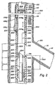
- FIGURE 2 is an enlarged cross-sectional view of a tubing exit sleeve 200 of the present invention deployed in a closed position.
- the tubing exit sleeve 200 has a body portion 202, which has an inner surface 206 that defines a substantially cylindrical inner bore 208. Threads 210 matingly receive the tubing string 122 such that a well tool can be routed from the surface 124 ( see FIGURE 1) to the inner bore 208 of the tubing body portion 202.
- a side port 212 Defined in the tubing body portion 202 is a side port 212.
- the side port is substantially aligned with the lateral wellbore 112 for access from the inner bore 208 in the nature of mechanical access with a well tool or fluid access.
- the sleeve recess 214 has an enlarged inner diameter ID 214 sufficient to receive the exit window sleeve 204 in a substantially-coaxial relation with respect to the tubing body 202. As shown, the inner diameter ID 204 of the exit window sleeve 204 is less than or equal to the inner diameter ID 202 of the tubing body portion 202 to minimize obstruction of the inner bore 208.
- exit-window sleeve can be used, such as a partial sleeve that forms a partial tube that can be received in grooves of the tubing body portion 202.
- the tubing sleeve can be received on the exterior of the body portion 202.
- the window sleeve 204 is received within the tubing body 202.
- the window sleeve 204 is rotationally-secured with the body portion 202 sufficient to maintain longitudinal alignment of a sleeve window 220, defined in the window sleeve 204, with the window port 212.
- a radial outward-extending projection or key may be provided on the window sleeve 204 and cooperatively slidingly-engaged with a groove or keyway formed internally on the body portion 202 to prevent relative circumferential displacement between the window sleeve 204 and the body portion 202.
- the exit window sleeve 204 can longitudinally reciprocate between a closed position limited by the recess shoulder 216, and an opened position limited by an opposing recess shoulder 218.
- the exit window sleeve 204 defines an exit window 220.
- the exit window 220 is dimensioned to accommodate well tools accessing the lateral wellbore 112.
- the window distance D window from a bottom end 232 of the window sleeve 204 to the bottom edge 234 of the sleeve window 220 is greater than the travel distance D travel between the open and closed position of the window sleeve 204.
- the distance D port from the shoulder 218 to the bottom edge 136 is greater than the travel distance D travel , and is greater than or equal to the window distance D window such that the sleeve window 220 is substantially aligned with the side port 212 when the bottom edge 232 of the window sleeve 204 is adjacent the shoulder 218 in the opened position, discussed later in detail.
- Driving the window sleeve between the open and closed position is provided by a hydraulically-responsive window sleeve piston 222, which is defined on the outer surface 224 of the window sleeve 204.
- the sleeve piston 222 is received in a longitudinally-extending piston chamber 226 defined in the tubing body portion 202.
- the cross-sectional profile of the sleeve piston 222 substantially-corresponds to the cross-sectional profile of the piston chamber 226.
- the sleeve piston 222 is responsive to a fluid pressure differential within the piston chamber 226.
- fluid as used herein means a material capable of flowing, and may include gases, liquids, plastics, and solids that can be handled in the manner of a liquid and has characteristics suitable for hydraulic use.
- the piston chamber 226 and the sleeve piston 222 are in a sealed relation with seals 230. Suitable seals are provided by O-rings received in grooves defined in the body portion 202 or the exit-window sleeve 204, accordingly.
- the seals 230 are preferably formed of a durable metal alloy.
- the sleeve piston is driven by a fluid pressure-differential generated across the piston 222 by the return-hydraulic line 128 a coupled to a return port 228 a , and the input-hydraulic line 128 b coupled to an input port 228 b .
- the position of the window sleeve 204 with respect to the tubing body portion 202 is sensed with a position sensor 238, such as inductance-shift sensor, or a magnetic position sensor.
- a magnetic-position sensor operates on the principal of shifts in magnetic fields, generally brought on by a magnetic field source reference.
- the position sensor 238 is a magnetic position sensor.
- the position sensor 238 as shown is of an exaggerated size to more clearly convey this aspect of the present invention.
- the position sensor is secured to the tubing body portion 202 such that it does not extend past the outer surface 207 of the tubing body portion 202 to minimize abrasive contact of the position sensor 238 with the casing 116 as the tool 200 is lowered into position.
- the magnetic field source 239 can be provided by a conventional magnet with a magnetic field strength sufficient to be sensed by the sensor 23 8. Referring to FIGURE 3, an enlarged illustration shows the interaction between the position sensor 238 and the magnetic field source 239 is shown.
- the region of the tubing body portion adjacent the sensor 238 is a magnetically-shielding steel ferromagnetic material.
- the window sleeve piston 222 has oppositely directed end faces, on which two magnets 239 a and 239 b are opposingly mounted adjacent the inner surface 106 of the tubing body portion 202.
- the respective magnetic axes are substantially longitudinally-aligned with the tubing body portion 202.
- the magnetic field source provided by the magnets 239 a and 239 b provides a magnetic main flux illustrated by magnetic flux lines M.
- the position sensor 238 is disposed on the outer surface 207 of the tubing body portion 202 to sense the magnetic field source 239. Accordingly, displacement of the window sleeve piston 222 along the longitudinal axis A generates a variation of the strength of the magnetic field sensed by the position sensor 238.
- the position sensor 238 registers the magnetic field M, which is then used to produce a switching signal on sensor conductors 128 c through an electrical output port or terminal.
- the electrical output of the position sensor 238 is transmitted to the surface control system 126 through the sensor conductor 128 c .
- the electrical output is then processed to determine whether the window sleeve 204 is in the closed or the opened position. Further detail concerning position sensors is available in U.S.
- Patent No. 5,231,352 issued July 27,1993 to Huber, which is incorporated herein by reference. It should be noted that other position sensing techniques of the exit window sleeve 204 with respect to the tubing body portion 202 can be deployed, such as that shown in U.S. Patent No. 5,532,585, issued July 2, 1996, to Oudet et al., which is incorporated herein by reference.
- the advantage of the position sensor 238 is to determine, before a trip to the exit tubing sleeve 200, whether a tooling operation can be conducted.
- the manipulation of multilateral equipment is done blind in that a series of commands are transmitted for a mechanical operation; but until well tools are sent downhole, it is not known whether the commands were received, or the downhole devices would or could properly respond to the commands.
- the position sensor 238 provides a positional status of the tubing exit sleeve 200 before further operations are commenced.
- a retrieval fishneck 242 defined on an inner surface and adjacent a top end 240 is a retrieval fishneck 242.
- the retrieval fishneck allows manual manipulation of the exit-window sleeve 204 with a latching device carried by a coiled tubing unit, which is known to those skilled in the art.
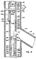
- FIGURE 4 is an enlarged cross-sectional view of the tubing exit sleeve 200 of the present invention deployed in an opened position. From the surface 124 ( see FIGURE 1), hydraulic pressure is increased through the hydraulic input line 128 b to urge the sleeve piston 222 downward, thus urging exit-window sleeve 204 to travel downward toward the shoulder 218, until the bottom end 232 of the exit-window sleeve 204 is adjacent the shoulder 218.
- the sleeve window 220 is substantially aligned with the side port 212 such that the inner bore 208 is in communication with the lateral wellbore 112.
- the sleeve window 220 is sufficiently smaller than the side port 212 to minimize a well tool impinging the tubing body portion 202 when exiting the window 200, while being sized sufficient to allow passage of the well service tool.
- the well tool referred to can be any number of devices used to service the lateral wellbore 112.
- the well service tool can be a through-tubing inflatable packer used to perform temporary well bore isolation or fluid diversion during treatments, or the like.
- the dimensions and the size are not meant to foreclose the use of other tools that may be developed at a later date.
- a diverter 250 diverts a well tool for access to the lateral wellbore 112.
- a diverter is a device that is generally a long, slender, tapered steel wedge 252 with a concave groove on its inclined face 254.
- the diverter 250 is supported in the body portion 202, or the tubing string 122, using techniques known to those skilled in the art, such as a nipple profiles and mating key profile extending from the diverter stem 255, or the like.
- an alignment key 256 extends from a centralizer 258, which aids in centralizing the stem 255 with respect to the tubing body portion 202.
- a centralizer 258 which aids in centralizing the stem 255 with respect to the tubing body portion 202.
- the diverter 250 As the diverter 250 is lowered into the tubing body, it engages a diverter orientation-and-depth-control slot 260 defined in the inner bore 208.
- the alignment key 256 engages the reception point 262 of the diverter slot 260, the inclined face 254 is oriented toward the window port 212, and at a depth relative to the body portion 202 sufficient to divert a well service tool from its course of travel toward the lateral wellbore 112.
- the diverter 250 is "locked" with respect to the body portion 202 to provide a stationary support to divert a well tool toward the lateral wellbore 112. It should be noted that the diverter 250 can be either a permanent fixture or can be wireline deployed as needed.
Landscapes
- Engineering & Computer Science (AREA)
- Life Sciences & Earth Sciences (AREA)
- Geology (AREA)
- Mining & Mineral Resources (AREA)
- Physics & Mathematics (AREA)
- Environmental & Geological Engineering (AREA)
- Fluid Mechanics (AREA)
- General Life Sciences & Earth Sciences (AREA)
- Geochemistry & Mineralogy (AREA)
- Mechanical Engineering (AREA)
- Earth Drilling (AREA)
- Selective Calling Equipment (AREA)
Claims (17)
- Eine Austrittfenstereinheit für eine Tieflochrohranordnung, umfassend: einen rohrförmigen Körperabschnitt (202), welcher eine Seitenöffnung (212) von einer ausreichenden Größe definiert, um ein Hindurchführen eines Bohrlochwerkzeugs durch dieselbe zu erlauben; und eine Hülse (204) neben dem genannten rohrförmigen Körperabschnitt (202), welche verschiebbar um eine Längsachse des genannten rohrförmigen Körperabschnitts (202) herum gekoppelt ist, dadurch gekennzeichnet, dass die Hülse (204) auf einen Fernsteuerungsbefehl reagiert, so dass ein in einer Seite der genannten Hülse definiertes Hülsenfenster (220) im Wesentlichen auf die genannte Seitenöffnung (212) in einem geöffneten Verhältnis ausgerichtet werden kann, so dass ein Bohrlochwerkzeug durch das im Wesentlichen auf dieselbe ausgerichtete Hülsenfenster (220) und die Seitenöffnung (212) hindurchgeführt werden kann, und der genannte Fernsteuerungsbefehl von einem von der Hülse entfernt gelegenen Standort an die Hülse übertragen werden kann.
- Eine Einheit nach Anspruch 1, bei welcher der Körperabschnitt rohrförmig ist.
- Eine Einheit nach Anspruch 2, weiter umfassend: einen Positionssensor (238) mit einer elektrischen Ausgabeöffnung, wobei der genannte Positionssensor (238) an dem genannten rohrförmigen Körperabschnitt (202) befestigt ist, so dass ein Verdrängen der genannten Hülse (204) im Verhältnis zu dem genannten rohrförmigen Körperabschnitt (202) von dem genannten Positionssensor (238) aufgespürt wird, und der genannte Sensor (238) überträgt ein Signal, welches mit einer Verdrängung durch die genannte elektrische Ausgabeöffnung korrespondiert.
- Eine Einheit nach Anspruch 3, bei welcher der genannte Positionssensor (238) eine magnetisches Feldquelle aufspürt, welche an der genannten Hülse (204) befestigt ist.
- Eine Einheit nach Anspruch 3, weiter umfassend: einen Trenner (250) mit einem Keil (252), welcher im Verhältnis zu dem genannten rohrförmigen Körperabschnitt (202) neben der genannten Seitenöffnung (212) befestigt ist, für das Umlenken eines Bohrlochwerkzeugs in Richtung des genannten, im Wesentlichen ausgerichteten Hülsenfensters (220) und der Seitenöffnung (212).
- Eine Einheit nach Anspruch 2, bei welcher die genannte Hülse (204) weiter umfasst: einen Kolben (222), welcher sich von der genannten Hülse (204) erstreckt; und eine Kolbenkammer (226), welche in dem genannten Körper definiert ist, welcher den genannten Kolben (222) empfängt, wobei die genannte Kolbenkammer (226) für das Bereitstellen eines Druckdifferentials über dem genannten Kolben (222) dient, und wobei das genannte Hülsenfenster (220) der genannten Hülse (204) wahlweise in eine im Verhältnis zu der genannten Seitenöffnung (212) des genannten Körperabschnitts (202) geöffnete und geschlossene Position geschoben werden kann.
- Eine Einheit nach Anspruch 5, bei welcher der genannte Fernsteuerungsbefehl durch ein hydraulisches Fluid in Verbindung mit der genannten Hülse (204) weitergeleitet wird.
- Eine Einheit nach Anspruch 2, bei welcher die genannte Hülse (204) weiter umfasst: ein in der genannten Hülse (204) definiertes Wiederauffindungsprofil (242), so dass die genannte Hülse (204) mechanisch manipuliert werden kann.
- Eine Einheit nach Anspruch 1 oder 2, weiter umfassend: eine Vorrichtung für das Fernaufspüren einer Verdrängung der Hülse (204) in Längsrichtung im Verhältnis zu dem Körperabschnitt.
- Eine Einheit nach Anspruch 2, bei welcher die Hülse hydraulisch getrieben ist, und verschiebbar innerhalb des genannten Körperteils (202) empfangen wird, so dass die genannte Hülse (204) zwischen einer geöffneten Position und einer geschlossenen Position verschoben werden kann, wobei das genannte Seitenfenster der Hülse in der genannten geöffneten Position im Wesentlichen auf die genannte Seitenöffnung ausgerichtet ist, um einem Bohrlochwerkzeug einen externen Zugang von dem genannten Körperabschnitt aus zu erlauben.
- Eine Einheit nach Anspruch 10, weiter umfassend: einen Längsverdrängungssensor (238), welcher an dem genannten rohrförmigen Körperabschnitt (202) und der genannten, hydraulisch betriebenen Hülse (204) befestigt ist; und einen distal mit dem genannten Längsverdrängungssensor (238) gekoppelten Empfänger, so dass eine Längsverdrängung der genannten, hydraulisch getriebenen Hülse (204) im Verhältnis zu dem genannten rohrförmigen Körperabschnitt (202) festgestellt werden kann.
- Eine Einheit nach Anspruch 11, bei welcher der genannte Längsverdrängungssensor (238) für einen Magnetfluß empfänglich ist.
- Eine Einheit nach Anspruch 11, bei welcher der genannte Empfänger elektrisch mit dem genannten Längsverdrängungssensor (238) gekoppelt ist.
- Eine Einheit nach Anspruch 11, bei welcher der genannte Empfänger akustisch mit dem Längsverdrängungssensor (238) gekoppelt ist.
- Ein Verfahren für das wahlweise Auswerten eines lateralen Bohrlochs eines multilateralen Bohrlochs, welches die folgenden Schritte umfasst: das Bereitstellen einer ferngesteuerten Rohraustritthülse (200) in dem multilateralen Bohrloch (100), wobei die Rohraustritthülse (200) einen Körperabschnitt (202) umfasst, welcher eine Seitenöffnung (212) und eine verschiebbare Seitenfensterhülse (204) definiert, welche um eine Achse des Körperabschnitts herum empfangen wird; und durch das ferngesteuerte Positionieren der Seitenfensterhülse (204) im Verhältnis zu dem Körperabschnitt gekennzeichnet, so dass ein Bohrlochwerkzeug durch Übertragen eines Fernsteuerungsbefehls an die ferngesteuerte Rohranordnungshülse in das laterale Bohrloch eingeführt werden kann, wobei derselbe von einem Standort, welcher von der Rohranordnungshülse entfernt liegt, an die Rohranordnungshülse übertragen wird.
- Ein Verfahren nach Anspruch 15, bei welchem das Fernsteuerungssignal durch einen hydraulischen Fluid mit der ferngesteuerten Rohranordnungshülse (200) in Verbindung gebracht wird.
- Ein Verfahren nach Anspruch 15 oder 16, weiter umfassend den folgenden Schritt: das Aufspüren der Längsposition der Seitenfensterhülse (204) im Verhältnis zu dem Körperabschnitt (202).
Applications Claiming Priority (3)
| Application Number | Priority Date | Filing Date | Title |
|---|---|---|---|
| US185384 | 1998-11-03 | ||
| US09/185,384 US6095248A (en) | 1998-11-03 | 1998-11-03 | Method and apparatus for remote control of a tubing exit sleeve |
| PCT/US1999/024991 WO2000026499A1 (en) | 1998-11-03 | 1999-10-26 | Method and apparatus for remote control of a tubing exit sleeve |
Publications (3)
| Publication Number | Publication Date |
|---|---|
| EP1129272A1 EP1129272A1 (de) | 2001-09-05 |
| EP1129272A4 EP1129272A4 (de) | 2002-03-27 |
| EP1129272B1 true EP1129272B1 (de) | 2006-01-04 |
Family
ID=22680759
Family Applications (1)
| Application Number | Title | Priority Date | Filing Date |
|---|---|---|---|
| EP99961530A Expired - Lifetime EP1129272B1 (de) | 1998-11-03 | 1999-10-26 | Verfahren und vorrichtung zur abstandsbedienung einer rohrausgangshülse |
Country Status (5)
| Country | Link |
|---|---|
| US (1) | US6095248A (de) |
| EP (1) | EP1129272B1 (de) |
| AU (1) | AU751270B2 (de) |
| NO (1) | NO325309B1 (de) |
| WO (1) | WO2000026499A1 (de) |
Cited By (2)
| Publication number | Priority date | Publication date | Assignee | Title |
|---|---|---|---|---|
| RU2451150C1 (ru) * | 2010-11-13 | 2012-05-20 | Государственное образовательное учреждение высшего профессионального образования Российский государственный университет нефти и газа имени И.М. Губкина | Способ строительства многозабойной скважины |
| RU2746987C1 (ru) * | 2017-11-17 | 2021-04-23 | Хэллибертон Энерджи Сервисиз, Инк. | Привод для системы многоствольной скважины |
Families Citing this family (21)
| Publication number | Priority date | Publication date | Assignee | Title |
|---|---|---|---|---|
| US6848504B2 (en) | 2002-07-26 | 2005-02-01 | Charles G. Brunet | Apparatus and method to complete a multilateral junction |
| US6935428B2 (en) * | 2002-08-12 | 2005-08-30 | Halliburton Energy Services, Inc. | Apparatus and methods for anchoring and orienting equipment in well casing |
| WO2007102821A1 (en) | 2006-03-09 | 2007-09-13 | Welldynamics, Inc. | Well tool having magnetically coupled position sensor |
| US7673683B2 (en) * | 2006-01-23 | 2010-03-09 | Welldynamics, Inc. | Well tool having magnetically coupled position sensor |
| BRPI0621049A2 (pt) * | 2006-01-23 | 2012-06-19 | Welldynamics Inc | ferramenta de poço para uso em associação com um poço subterráneo |
| US8196656B2 (en) | 2007-09-19 | 2012-06-12 | Welldynamics, Inc. | Position sensor for well tools |
| US20090255687A1 (en) * | 2008-04-10 | 2009-10-15 | Halliburton Energy Services, Inc. | Sealing Between Alignable Windows for Lateral Wellbore Drilling |
| US9260921B2 (en) | 2008-05-20 | 2016-02-16 | Halliburton Energy Services, Inc. | System and methods for constructing and fracture stimulating multiple ultra-short radius laterals from a parent well |
| US9181796B2 (en) | 2011-01-21 | 2015-11-10 | Schlumberger Technology Corporation | Downhole sand control apparatus and method with tool position sensor |
| US8752631B2 (en) * | 2011-04-07 | 2014-06-17 | Baker Hughes Incorporated | Annular circulation valve and methods of using same |
| EP3495603A1 (de) | 2012-04-30 | 2019-06-12 | Halliburton Energy Services Inc. | Bohrrohrabschnitt mit beweglichem abschnitt zur bereitstellung eines bohrrohrausgangs |
| WO2014049017A1 (de) | 2012-09-27 | 2014-04-03 | Wintershall Holding GmbH | Verfahren zum gerichteten fracen einer unterirdischen formation, in die mindestens eine abgelenkte bohrung abgeteuft ist |
| GB201414256D0 (en) * | 2014-08-12 | 2014-09-24 | Meta Downhole Ltd | Apparatus and method of connecting tubular members in multi-lateral wellbores |
| MX2018004677A (es) | 2015-11-06 | 2018-06-18 | Halliburton Energy Services Inc | Deteccion de posicion de un dispositivo movil usando adquisicion de registros de induccion electromagnetica. |
| WO2017209753A1 (en) * | 2016-06-02 | 2017-12-07 | Halliburton Energy Services, Inc. | Multilateral intelligent completion with stackable isolation |
| WO2019099037A1 (en) * | 2017-11-17 | 2019-05-23 | Halliburton Energy Services, Inc. | Actuator for multilateral wellbore system |
| CN111101858B (zh) * | 2018-10-29 | 2024-12-13 | 中国石油化工股份有限公司 | 侧钻井可选择免钻磨完井装置和方法 |
| US11692417B2 (en) | 2020-11-24 | 2023-07-04 | Saudi Arabian Oil Company | Advanced lateral accessibility, segmented monitoring, and control of multi-lateral wells |
| US20220389795A1 (en) * | 2021-06-07 | 2022-12-08 | Halliburton Energy Services, Inc. | Whipstock with one or more high-expansion members for passing through small restrictions |
| US11867030B2 (en) * | 2021-11-29 | 2024-01-09 | Halliburton Energy Services, Inc. | Slidable isolation sleeve with I-shaped seal |
| US11851992B2 (en) * | 2021-11-29 | 2023-12-26 | Halliburton Energy Services, Inc. | Isolation sleeve with I-shaped seal |
Family Cites Families (9)
| Publication number | Priority date | Publication date | Assignee | Title |
|---|---|---|---|---|
| DE8901770U1 (de) * | 1989-02-15 | 1990-07-26 | Schaltbau GmbH, 8000 München | Stellantrieb |
| FR2691534B1 (fr) * | 1992-05-19 | 1994-08-26 | Moving Magnet Tech | Capteur de position à aimant permanent et sonde de hall. |
| US5564503A (en) * | 1994-08-26 | 1996-10-15 | Halliburton Company | Methods and systems for subterranean multilateral well drilling and completion |
| US5566763A (en) * | 1994-08-26 | 1996-10-22 | Halliburton Company | Decentralizing, centralizing, locating and orienting subsystems and methods for subterranean multilateral well drilling and completion |
| US5547029A (en) * | 1994-09-27 | 1996-08-20 | Rubbo; Richard P. | Surface controlled reservoir analysis and management system |
| US5666050A (en) * | 1995-11-20 | 1997-09-09 | Pes, Inc. | Downhole magnetic position sensor |
| US5730224A (en) * | 1996-02-29 | 1998-03-24 | Halliburton Energy Services, Inc. | Slidable access control device for subterranean lateral well drilling and completion |
| US5918669A (en) * | 1996-04-26 | 1999-07-06 | Camco International, Inc. | Method and apparatus for remote control of multilateral wells |
| EP0966653B1 (de) * | 1997-03-12 | 2003-05-14 | Pepperl + Fuchs Gmbh | Verfahren und vorrichtung zur positionserfassung eines beweglich angeordneten stellglieds eines stellantriebs |
-
1998
- 1998-11-03 US US09/185,384 patent/US6095248A/en not_active Expired - Lifetime
-
1999
- 1999-10-26 AU AU18085/00A patent/AU751270B2/en not_active Expired
- 1999-10-26 WO PCT/US1999/024991 patent/WO2000026499A1/en not_active Ceased
- 1999-10-26 EP EP99961530A patent/EP1129272B1/de not_active Expired - Lifetime
-
2001
- 2001-04-30 NO NO20012132A patent/NO325309B1/no not_active IP Right Cessation
Cited By (2)
| Publication number | Priority date | Publication date | Assignee | Title |
|---|---|---|---|---|
| RU2451150C1 (ru) * | 2010-11-13 | 2012-05-20 | Государственное образовательное учреждение высшего профессионального образования Российский государственный университет нефти и газа имени И.М. Губкина | Способ строительства многозабойной скважины |
| RU2746987C1 (ru) * | 2017-11-17 | 2021-04-23 | Хэллибертон Энерджи Сервисиз, Инк. | Привод для системы многоствольной скважины |
Also Published As
| Publication number | Publication date |
|---|---|
| EP1129272A1 (de) | 2001-09-05 |
| NO20012132L (no) | 2001-04-30 |
| US6095248A (en) | 2000-08-01 |
| WO2000026499A1 (en) | 2000-05-11 |
| NO325309B1 (no) | 2008-03-25 |
| AU751270B2 (en) | 2002-08-08 |
| AU1808500A (en) | 2000-05-22 |
| NO20012132D0 (no) | 2001-04-30 |
| EP1129272A4 (de) | 2002-03-27 |
Similar Documents
| Publication | Publication Date | Title |
|---|---|---|
| AU751270B2 (en) | Method and apparatus for remote control of a tubing exit sleeve | |
| US11002367B2 (en) | Valve system | |
| AU2017271008B2 (en) | Well with pressure activated acoustic or electromagnetic transmitter | |
| US5803167A (en) | Computer controlled downhole tools for production well control | |
| US6766857B2 (en) | Thru-tubing sand control method and apparatus | |
| US6237683B1 (en) | Wellbore flow control device | |
| US6041864A (en) | Well isolation system | |
| CA2448419C (en) | Instrumentation for a downhole deployment valve | |
| WO1996012868A1 (en) | Method and system for operating a downhole tool | |
| GB2359574A (en) | Access and flow control between a main and lateral bore | |
| CA2061571C (en) | Hydraulic system for electronically controlled downhole testing tool | |
| EP3688273B1 (de) | Ein bohrloch mit zwei gehäusen | |
| EP2872726B1 (de) | Doppelrohr-kolbenanschlagsystem | |
| EP4323623B1 (de) | Rückholbare packervorrichtung | |
| CA2320195C (en) | Sidepocket mandrel for orienting a gas lift valve | |
| AU734606B2 (en) | Computer controlled downhole tools for production well control | |
| CA2573379C (en) | Wellbore flow control device |
Legal Events
| Date | Code | Title | Description |
|---|---|---|---|
| PUAI | Public reference made under article 153(3) epc to a published international application that has entered the european phase |
Free format text: ORIGINAL CODE: 0009012 |
|
| 17P | Request for examination filed |
Effective date: 20010523 |
|
| AK | Designated contracting states |
Kind code of ref document: A1 Designated state(s): AT BE CH CY DE DK ES FI FR GB GR IE IT LI LU MC NL PT SE |
|
| AX | Request for extension of the european patent |
Free format text: AL;LT;LV;MK;RO;SI |
|
| RIC1 | Information provided on ipc code assigned before grant |
Free format text: 7E 21B 17/00 A, 7E 21B 41/00 B |
|
| A4 | Supplementary search report drawn up and despatched |
Effective date: 20020212 |
|
| AK | Designated contracting states |
Kind code of ref document: A4 Designated state(s): AT BE CH CY DE DK ES FI FR GB GR IE IT LI LU MC NL PT SE |
|
| 17Q | First examination report despatched |
Effective date: 20020809 |
|
| REG | Reference to a national code |
Ref country code: DE Ref legal event code: 8566 |
|
| RBV | Designated contracting states (corrected) |
Designated state(s): FR GB |
|
| GRAP | Despatch of communication of intention to grant a patent |
Free format text: ORIGINAL CODE: EPIDOSNIGR1 |
|
| GRAS | Grant fee paid |
Free format text: ORIGINAL CODE: EPIDOSNIGR3 |
|
| GRAA | (expected) grant |
Free format text: ORIGINAL CODE: 0009210 |
|
| AK | Designated contracting states |
Kind code of ref document: B1 Designated state(s): FR GB |
|
| REG | Reference to a national code |
Ref country code: GB Ref legal event code: FG4D |
|
| ET | Fr: translation filed | ||
| PLBE | No opposition filed within time limit |
Free format text: ORIGINAL CODE: 0009261 |
|
| STAA | Information on the status of an ep patent application or granted ep patent |
Free format text: STATUS: NO OPPOSITION FILED WITHIN TIME LIMIT |
|
| 26N | No opposition filed |
Effective date: 20061005 |
|
| REG | Reference to a national code |
Ref country code: FR Ref legal event code: PLFP Year of fee payment: 18 |
|
| REG | Reference to a national code |
Ref country code: FR Ref legal event code: PLFP Year of fee payment: 19 |
|
| REG | Reference to a national code |
Ref country code: FR Ref legal event code: PLFP Year of fee payment: 20 |
|
| PGFP | Annual fee paid to national office [announced via postgrant information from national office to epo] |
Ref country code: FR Payment date: 20180928 Year of fee payment: 20 |
|
| PGFP | Annual fee paid to national office [announced via postgrant information from national office to epo] |
Ref country code: GB Payment date: 20180814 Year of fee payment: 20 |
|
| REG | Reference to a national code |
Ref country code: GB Ref legal event code: PE20 Expiry date: 20191025 |
|
| PG25 | Lapsed in a contracting state [announced via postgrant information from national office to epo] |
Ref country code: GB Free format text: LAPSE BECAUSE OF EXPIRATION OF PROTECTION Effective date: 20191025 |