EP1129461B1 - Relais a element de couplage - Google Patents
Relais a element de couplage Download PDFInfo
- Publication number
- EP1129461B1 EP1129461B1 EP99971962A EP99971962A EP1129461B1 EP 1129461 B1 EP1129461 B1 EP 1129461B1 EP 99971962 A EP99971962 A EP 99971962A EP 99971962 A EP99971962 A EP 99971962A EP 1129461 B1 EP1129461 B1 EP 1129461B1
- Authority
- EP
- European Patent Office
- Prior art keywords
- spring
- coupling element
- relay
- coupling
- contact springs
- Prior art date
- Legal status (The legal status is an assumption and is not a legal conclusion. Google has not performed a legal analysis and makes no representation as to the accuracy of the status listed.)
- Expired - Lifetime
Links
- 230000008878 coupling Effects 0.000 title claims abstract description 49
- 238000010168 coupling process Methods 0.000 title claims abstract description 49
- 238000005859 coupling reaction Methods 0.000 title claims abstract description 49
- 239000011810 insulating material Substances 0.000 claims description 2
- 238000005192 partition Methods 0.000 description 10
- 239000000853 adhesive Substances 0.000 description 2
- 230000001070 adhesive effect Effects 0.000 description 2
- 238000013459 approach Methods 0.000 description 2
- 125000006850 spacer group Chemical group 0.000 description 2
- 230000000903 blocking effect Effects 0.000 description 1
- 238000005516 engineering process Methods 0.000 description 1
- 239000012530 fluid Substances 0.000 description 1
- 238000002955 isolation Methods 0.000 description 1
- 239000007788 liquid Substances 0.000 description 1
- 239000000126 substance Substances 0.000 description 1
- 210000004243 sweat Anatomy 0.000 description 1
Images


Classifications
-
- H—ELECTRICITY
- H01—ELECTRIC ELEMENTS
- H01H—ELECTRIC SWITCHES; RELAYS; SELECTORS; EMERGENCY PROTECTIVE DEVICES
- H01H50/00—Details of electromagnetic relays
- H01H50/02—Bases; Casings; Covers
- H01H50/04—Mounting complete relay or separate parts of relay on a base or inside a case
- H01H50/047—Details concerning mounting a relays
-
- H—ELECTRICITY
- H01—ELECTRIC ELEMENTS
- H01H—ELECTRIC SWITCHES; RELAYS; SELECTORS; EMERGENCY PROTECTIVE DEVICES
- H01H50/00—Details of electromagnetic relays
- H01H50/02—Bases; Casings; Covers
- H01H50/04—Mounting complete relay or separate parts of relay on a base or inside a case
- H01H2050/049—Assembling or mounting multiple relays in one common housing
Definitions
- the invention relates to a relay with a coupling element, according to the preamble of Claim 1 (DE-A-19 600 314).
- a relay with a coupling element according to the preamble of Claim 1 (DE-A-19 600 314).
- Double or triple relay functions to get out of a "single relay” to make a “twin” or “triplet”.
- Such a need exists especially in security technology, where it is important that in Error, for example when merging or blocking contacts there are still parallel contacts that take over the switching function.
- Another need is to use as little wiring as possible to accommodate a large number of relay contacts in the smallest possible space. Again, it is necessary to perform certain electrical functions of the single relay transferred to the twin made from it, in order to to avoid unwanted redundancy. For example, in this case it is desires that in a relay twin all passive contact springs both the one as well as the other spring box on the same electrical potential lie. But you don’t want to make any connections on a circuit board, which meets this requirement, but the contact springs should immediately be electrically connected.
- the invention is therefore based on the object of a relay of the input mentioned type so to form that without circuitry to a relay twin or a relay triplet can be formed.
- a coupling element is provided which mechanically couples several spring brackets to one another.
- a single relay can be quickly connected via a connection Coupling element to a multiple relay, e.g. B. a relay twin or a relay triplet.
- the coupling element also carries the electrical through connection between the spring brackets in itself, so that an external connection effort (e.g. via a circuit board on which the relays are seated with their connecting pins) is avoided. and that with the help of the mechanical coupling of the coupling element, the electrical coupling of the spring brackets to be connected is simultaneously produced.
- the electrical connection of the interconnecting spring brackets takes place via the passive contact springs.
- individual passive contact springs are no longer assigned to the respective spring block, but that one of the two spring blocks is assigned a double contact spring which consists of two individual contact springs which are connected to one another by means of an electrically conductive connecting web.
- This has the advantage that such a double contact spring is first connected to the coupling element and that the coupling element is then connected to the spring brackets to be connected, so that one spring of the double contact spring forms, for example, the passive contact spring of a spring bracket, while the other spring Double contact spring, which forms the other passive contact spring of the other spring bracket. Both contact springs are then due to their electrical connection via the connecting web which penetrates the contact element at the same electrical potential.
- active and passive contact springs should not be understood as restricting intellectual property rights. Rather, it is within the scope of the invention, instead of the passive contact springs described here, to connect the active contact springs in an electrically conductive manner by means of a contact element via a coupling element in that the respective associated contact spring is arranged on each side of the coupling element and the electrically conductive connection between this contact springs is brought about by a connecting web which passes through the coupling element and is fastened to it.
- the Coupling of the coupling element latching and releasable with the connecting spring brackets is formed.
- the Coupling of the coupling element with the spring brackets is fixed. It can be an adhesive, sweat or other liquid substance Connection.
- a particularly compact structure results when the active and passive contact springs are arranged at an angle of 90 °.
- the coupling element made of an insulating material exists and at least one parallel to the contact rows of the relay has running partition on which side lugs are formed, which engage in assigned receiving openings on the respective spring bracket.
- Grooves are formed between the lateral approaches of the partition, which are suitable for receiving the contact springs.
- parallel to the longitudinal axes of the receiving openings in the respective spring bracket to the front Open slots are arranged, there can be the passive contact springs be inserted.
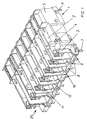
- the single relay consists of a spring bracket 1 on which the drive 5 is arranged.
- An active contact spring 2 is lying on the spring bracket 1 arranged, which is actuated by an actuator 4.
- Standing in the spring trestle a passive contact spring 3 each arranged. All contact sets are in one Contact row 25 arranged, the contact sets from each other assigned partitions 12 are separated from each other.
- the respective passive contact spring is located on a housing-fixed Dock 11 on.
- the drive system is led out downwards Pins 6 contacted, as well as the active and passive contact springs 2, 3 are led out downwards by assigned connecting pins 7.
- the one end face of the spring bracket 1 has receiving openings 8 which are open at the end and which are intended for the engagement of associated projections 16 of a coupling element 14. Between the receiving openings 8, slots 9 are formed, into which the passive contact springs 3 are inserted from the front side and are held there. The mounting is carried out by multiple cranked grooves 10, so that a cheap, stable mounting of the respective contact spring 3 is guaranteed.
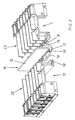
- a relay twin according to FIGS. 2 to 4 is now to be created from the relay single according to FIG. 1.
- the coupling element 14 is provided, which essentially consists of a plastic part which has a central partition wall 15, the height of which corresponds approximately to the height of the spring bracket 1,13.
- the lugs 16, which are intended to engage in the associated receiving openings 8 of the spring brackets 1, 13, extend from the partition wall 12 in opposite directions.
- the partition 15 forms an approximately T-shaped shape in the lower region a cross member 20 formed on the partition 15, on the underside thereof Support ribs 17 are arranged.
- a cheap, rigid, mechanical connection between the spring brackets to be connected 1.13 reached because, as shown in Figure 3, the cross member 20 engages in one assigned, one-sided, open snap-in receptacle 19 and is assigned there Locking means 18 set.
- Spacer ribs 24 are also arranged laterally on the partition 15, which are spaced for the assigned end faces of the receiving openings 8. At these spacing ribs 24, the end faces of the Receiving openings 8 of the respective spring blocks 1.13.
- Double contact spring 21 is provided, as shown in Figure 4.
- she consists from the aforementioned passive contact springs 3, which by means of an electrical conductive connecting web 22 are interconnected.
Landscapes
- Physics & Mathematics (AREA)
- Electromagnetism (AREA)
- Coupling Device And Connection With Printed Circuit (AREA)
- Connections Arranged To Contact A Plurality Of Conductors (AREA)
- Switch Cases, Indication, And Locking (AREA)
- Details Of Connecting Devices For Male And Female Coupling (AREA)
Claims (10)
- Relais avec élément de couplage, ledit relais étant constitué d'au moins un bloc à lames (1 ou 13) dans lequel est agencé un entraínement (5) qui sollicite au moins une lame de contact active (2) via un actionneur (4), ladite lame de contact active coopérant avec au moins une lame de contact passive (3) ancrée dans le bloc à lames à respectif (1, 13), les lames de contact (2,3) étant susceptibles d'être mises en contact électrique via des contacts de raccordement respectifs (7), caractérisé en ce que le relais est susceptible d'être accouplé mécaniquement à au moins un autre relais de même genre, actionné indépendamment de celui-ci, via des dispositifs de couplage respectifs (8) des blocs à lames (1, 13) au moyen d'un élément de couplage (14) réalisé sous forme de composant séparé, les contacts de raccordement électriques (5) des lames de contact (2, 3) du relais étant agencés dans la zone des dispositifs de couplage (8) respectifs, et en ce que les relais accouplés sont disposés à symétrie par rapport à l'élément de couplage (14).
- Relais selon la revendication 1, caractérisé en ce que les lames de contact actives (2) et/ou les lames de contact passives (3) des blocs à lames (1 et 13) dudit relais sont également couplées électriquement les unes aux autres via l'élément d'accouplement séparé (14).
- Relais selon l'une ou l'autre des revendications 1 et 2, caractérisé en ce que l'accouplement de l'élément d'accouplement (14) est réalisé avec enclenchement et de façon libérable.
- Relais selon l'une ou l'autre des revendications 1 et 2, caractérisé en ce que l'accouplement de l'élément d'accouplement (14) est réalisé de manière fixe.
- Relais selon l'une des revendications 1 à 4, caractérisé en ce que l'élément d'accouplement (14) est réalisé en matériau isolant et comporte un au moins une paroi de séparation (15) qui sépare de façon isolante les lames de contact (2, 3 ; 2, 21) du relais accouplé respectif, paroi sur laquelle sont conformés des talons latéraux (16) qui s'engagent dans des ouvertures de logement (8) associées sur le bloc à lames respectif (1 et 13) du relais respectif accouplé.
- Relais selon la revendication 5, caractérisé en ce que des rainures (23) sont ménagées entre les talons latéraux (16) de la paroi de séparation (15), lesdites rainures étant appropriées à recevoir des lames de contact (3 ; 21).
- Relais selon l'une des revendications 1 à 6, caractérisé en ce que des fentes (9), ouvertes vers la face frontale, sont agencées parallèlement aux axes longitudinaux des ouvertures de logement (8) dans les blocs à lames respectifs (1, 13) du relais, fentes dans lesquelles sont enfilées les lames de contact passives (3 ; 21).
- Relais selon l'une ou l'autre des revendications 6 et 7, caractérisé en ce que pour la liaison électrique des lames de contact passives (3) des blocs à lames (1, 13) des deux relais, au moins une lame de contact double (21) est susceptible d'être enfilée dans les rainures (23) de l'élément d'accouplement (14).
- Relais selon la revendication 8, caractérisé en ce que l'accouplement électrique des lames de contact passives des deux blocs à lames (1, 13) a lieu du fait qu'au moins une lame de contact double (21) est tout d'abord reliée à l'élément d'accouplement (14), et que l'élément d'accouplement (14) est alors enclenché avec les blocs à lames (1, 13).
- Relais selon l'une des revendications 1 à 9, caractérisé en ce que les lames de contact actives (2) et les lames de contact passives (3) sont agencées sous un angle de 90° les unes par rapport aux autres.
Applications Claiming Priority (3)
| Application Number | Priority Date | Filing Date | Title |
|---|---|---|---|
| DE19851507 | 1998-11-09 | ||
| DE19851507A DE19851507A1 (de) | 1998-11-09 | 1998-11-09 | Relais mit Koppelelement |
| PCT/EP1999/008177 WO2000028563A1 (fr) | 1998-11-09 | 1999-10-28 | Relais a element de couplage |
Publications (2)
| Publication Number | Publication Date |
|---|---|
| EP1129461A1 EP1129461A1 (fr) | 2001-09-05 |
| EP1129461B1 true EP1129461B1 (fr) | 2002-09-11 |
Family
ID=7887115
Family Applications (1)
| Application Number | Title | Priority Date | Filing Date |
|---|---|---|---|
| EP99971962A Expired - Lifetime EP1129461B1 (fr) | 1998-11-09 | 1999-10-28 | Relais a element de couplage |
Country Status (6)
| Country | Link |
|---|---|
| US (1) | US6778047B1 (fr) |
| EP (1) | EP1129461B1 (fr) |
| JP (1) | JP3888605B2 (fr) |
| AT (1) | ATE224096T1 (fr) |
| DE (2) | DE19851507A1 (fr) |
| WO (1) | WO2000028563A1 (fr) |
Families Citing this family (4)
| Publication number | Priority date | Publication date | Assignee | Title |
|---|---|---|---|---|
| DE102007037333A1 (de) * | 2007-08-08 | 2009-02-26 | Daimler Ag | Betätigungsvorrichtung |
| CN103681119A (zh) * | 2012-09-20 | 2014-03-26 | 昆山维安盛电子有限公司 | 接触器 |
| KR101917885B1 (ko) | 2012-09-26 | 2018-11-13 | 현대일렉트릭앤에너지시스템(주) | 전자접촉기 |
| EP4235727A1 (fr) * | 2022-02-16 | 2023-08-30 | Solaredge Technologies Ltd. | Relais électromécanique verrouillé |
Family Cites Families (11)
| Publication number | Priority date | Publication date | Assignee | Title |
|---|---|---|---|---|
| NL107963C (fr) * | 1956-09-07 | |||
| FR1236552A (fr) * | 1959-06-08 | 1960-07-22 | Telemecanique Electrique | Perfectionnements aux relais dits débrochables |
| DE1590621A1 (de) * | 1966-10-20 | 1970-06-25 | Stotz Kontakt Gmbh | Elektrisches Schaltschuetz mit einer Schalter- und Magneteinheit |
| JPS52232B2 (fr) * | 1972-04-21 | 1977-01-06 | ||
| US5081436A (en) * | 1988-11-22 | 1992-01-14 | Omron Corporation | Electromagnetic relay having an improved terminal structure |
| GB2229038B (en) * | 1989-03-07 | 1994-01-26 | Matsushita Electric Works Ltd | Electromagnetic contactor |
| JPH07120496B2 (ja) | 1989-09-25 | 1995-12-20 | 三菱電機株式会社 | 電磁接触器 |
| JP3031420B2 (ja) | 1989-12-08 | 2000-04-10 | ローランド株式会社 | 共鳴効果装置 |
| DE19600314C2 (de) * | 1996-01-06 | 1999-02-04 | Hengstler Gmbh | Relais mit zwangsgeführten Kontaktsätzen |
| US5805040A (en) * | 1996-09-27 | 1998-09-08 | Simens Electromechanical Components, Inc. | Relay base and method of assembly |
| EP0954001A1 (fr) * | 1998-04-30 | 1999-11-03 | ELESTA relays GmbH | Relais avec des contacts guidés |
-
1998
- 1998-11-09 DE DE19851507A patent/DE19851507A1/de not_active Withdrawn
-
1999
- 1999-10-28 US US09/831,223 patent/US6778047B1/en not_active Expired - Fee Related
- 1999-10-28 WO PCT/EP1999/008177 patent/WO2000028563A1/fr not_active Ceased
- 1999-10-28 EP EP99971962A patent/EP1129461B1/fr not_active Expired - Lifetime
- 1999-10-28 DE DE59902687T patent/DE59902687D1/de not_active Expired - Lifetime
- 1999-10-28 JP JP2000581664A patent/JP3888605B2/ja not_active Expired - Fee Related
- 1999-10-28 AT AT99971962T patent/ATE224096T1/de active
Also Published As
| Publication number | Publication date |
|---|---|
| JP2002529898A (ja) | 2002-09-10 |
| WO2000028563A1 (fr) | 2000-05-18 |
| EP1129461A1 (fr) | 2001-09-05 |
| DE19851507A1 (de) | 2000-05-11 |
| DE59902687D1 (de) | 2002-10-17 |
| ATE224096T1 (de) | 2002-09-15 |
| US6778047B1 (en) | 2004-08-17 |
| JP3888605B2 (ja) | 2007-03-07 |
Similar Documents
| Publication | Publication Date | Title |
|---|---|---|
| DE2234435C2 (de) | Überbrückungsadapter für Stromverteilerschienen | |
| DE69121270T2 (de) | Zweiteilige Buchseneinheit für modularen Steckeraufbau | |
| DE602005000149T2 (de) | Anschlussanordnung eines elektrischen Gerätes | |
| DE3903839A1 (de) | Beweglicher verbindungsstecker | |
| DE3326933A1 (de) | Schaltungsplatten-verbindungsanordnung | |
| DE19964156A1 (de) | Elektrisches Gerät | |
| EP0888706B1 (fr) | Controleur programmable | |
| DE69323124T2 (de) | Vorrichtung zur selektiven Herstellung von elektrischen Verbindungen zwischen einer Reihe von Leitern | |
| EP1117158B1 (fr) | Dispositif de blindage de fixation d'élements de raccordement | |
| DE3426949A1 (de) | Elektrischer schalter | |
| EP0474082A1 (fr) | Dispositif de codage avec des contacts spéciaux intégrés pour assemblages électriques enfichables sur un câblage de panneau arrière | |
| EP1129461B1 (fr) | Relais a element de couplage | |
| DE69709533T2 (de) | Verbindungsmodul mit Durchverbindung von Anschlüssen mittels eines oder mehreren beweglichen leitenden Teilen | |
| DE3943752C2 (de) | Pneumatische oder hydraulische Ventileinheit | |
| DE2847116C2 (de) | Kabelverbindung für Wählvermittlungsanlagen | |
| EP0239785B1 (fr) | Listeau de centrage pour l'enfichage sur une plaque murale de conducteurs pourvue de contacts auto-dénudants | |
| DE3442056A1 (de) | Steckverbindervorrichtung | |
| DE69900187T2 (de) | Ein Steckertreiber für das Zusammenfügen einer Mehrzahl von Steckern mit einer Mehrzahl von Gegensteckern | |
| DE2802643C2 (fr) | ||
| DE1933201A1 (de) | Vorrichtung zum stromuebertragenden Verbinden von elektrischen Leitungen | |
| EP0809332A1 (fr) | Connecteur électrique | |
| EP0746059B1 (fr) | Connecteur électrique | |
| EP0330119A2 (fr) | Connexion à fiches pour câbles électriques | |
| DE10243313A1 (de) | Kodierbarer Steckverbinder | |
| EP1356548A1 (fr) | Dispositif de contact pour la liaison liberable d'un bloc d'assemblage mobile avec des rails conducteurs fixes |
Legal Events
| Date | Code | Title | Description |
|---|---|---|---|
| PUAI | Public reference made under article 153(3) epc to a published international application that has entered the european phase |
Free format text: ORIGINAL CODE: 0009012 |
|
| 17P | Request for examination filed |
Effective date: 20010425 |
|
| AK | Designated contracting states |
Kind code of ref document: A1 Designated state(s): AT BE CH CY DE DK ES FI FR GB GR IE IT LI LU MC NL PT SE |
|
| GRAG | Despatch of communication of intention to grant |
Free format text: ORIGINAL CODE: EPIDOS AGRA |
|
| 17Q | First examination report despatched |
Effective date: 20011228 |
|
| GRAG | Despatch of communication of intention to grant |
Free format text: ORIGINAL CODE: EPIDOS AGRA |
|
| GRAH | Despatch of communication of intention to grant a patent |
Free format text: ORIGINAL CODE: EPIDOS IGRA |
|
| GRAH | Despatch of communication of intention to grant a patent |
Free format text: ORIGINAL CODE: EPIDOS IGRA |
|
| GRAA | (expected) grant |
Free format text: ORIGINAL CODE: 0009210 |
|
| AK | Designated contracting states |
Kind code of ref document: B1 Designated state(s): AT CH DE LI |
|
| REF | Corresponds to: |
Ref document number: 224096 Country of ref document: AT Date of ref document: 20020915 Kind code of ref document: T |
|
| REG | Reference to a national code |
Ref country code: CH Ref legal event code: EP |
|
| RAP2 | Party data changed (patent owner data changed or rights of a patent transferred) |
Owner name: HENGSTLER GMBH GESCHAEFTSBEREICH BAUELEMENTE |
|
| REF | Corresponds to: |
Ref document number: 59902687 Country of ref document: DE Date of ref document: 20021017 |
|
| REG | Reference to a national code |
Ref country code: CH Ref legal event code: NV Representative=s name: LUCHS & PARTNER PATENTANWAELTE |
|
| REG | Reference to a national code |
Ref country code: CH Ref legal event code: PFA Free format text: HENGSTLER GMBH GESCHAEFTSBEREICH BAUELEMENTE TRANSFER- HENGSTLER GMBH |
|
| PLBE | No opposition filed within time limit |
Free format text: ORIGINAL CODE: 0009261 |
|
| STAA | Information on the status of an ep patent application or granted ep patent |
Free format text: STATUS: NO OPPOSITION FILED WITHIN TIME LIMIT |
|
| 26N | No opposition filed |
Effective date: 20030612 |
|
| PGFP | Annual fee paid to national office [announced via postgrant information from national office to epo] |
Ref country code: DE Payment date: 20151022 Year of fee payment: 17 Ref country code: CH Payment date: 20151026 Year of fee payment: 17 |
|
| PGFP | Annual fee paid to national office [announced via postgrant information from national office to epo] |
Ref country code: AT Payment date: 20151022 Year of fee payment: 17 |
|
| REG | Reference to a national code |
Ref country code: DE Ref legal event code: R119 Ref document number: 59902687 Country of ref document: DE |
|
| REG | Reference to a national code |
Ref country code: CH Ref legal event code: PL |
|
| REG | Reference to a national code |
Ref country code: AT Ref legal event code: MM01 Ref document number: 224096 Country of ref document: AT Kind code of ref document: T Effective date: 20161028 |
|
| PG25 | Lapsed in a contracting state [announced via postgrant information from national office to epo] |
Ref country code: CH Free format text: LAPSE BECAUSE OF NON-PAYMENT OF DUE FEES Effective date: 20161031 Ref country code: DE Free format text: LAPSE BECAUSE OF NON-PAYMENT OF DUE FEES Effective date: 20170503 Ref country code: LI Free format text: LAPSE BECAUSE OF NON-PAYMENT OF DUE FEES Effective date: 20161031 |
|
| PG25 | Lapsed in a contracting state [announced via postgrant information from national office to epo] |
Ref country code: AT Free format text: LAPSE BECAUSE OF NON-PAYMENT OF DUE FEES Effective date: 20161028 |
|
| REG | Reference to a national code |
Ref country code: CH Ref legal event code: SPCP Owner name: AMGEN K-A, INC., US Spc suppl protection certif: C01124961/01 |