EP1129611A2 - Rollballenpresse für landwirtschaftliche Halmgüter - Google Patents
Rollballenpresse für landwirtschaftliche Halmgüter Download PDFInfo
- Publication number
- EP1129611A2 EP1129611A2 EP01101884A EP01101884A EP1129611A2 EP 1129611 A2 EP1129611 A2 EP 1129611A2 EP 01101884 A EP01101884 A EP 01101884A EP 01101884 A EP01101884 A EP 01101884A EP 1129611 A2 EP1129611 A2 EP 1129611A2
- Authority
- EP
- European Patent Office
- Prior art keywords
- roll
- transport device
- roll baler
- material web
- baler according
- Prior art date
- Legal status (The legal status is an assumption and is not a legal conclusion. Google has not performed a legal analysis and makes no representation as to the accuracy of the status listed.)
- Granted
Links
- 239000000463 material Substances 0.000 claims abstract description 27
- 230000032258 transport Effects 0.000 description 26
- 229910000746 Structural steel Inorganic materials 0.000 description 4
- 238000003780 insertion Methods 0.000 description 3
- 230000037431 insertion Effects 0.000 description 3
- 240000008025 Alternanthera ficoidea Species 0.000 description 1
- 230000009286 beneficial effect Effects 0.000 description 1
- 230000005540 biological transmission Effects 0.000 description 1
- 238000005096 rolling process Methods 0.000 description 1
- 238000011144 upstream manufacturing Methods 0.000 description 1
Images

Classifications
-
- A—HUMAN NECESSITIES
- A01—AGRICULTURE; FORESTRY; ANIMAL HUSBANDRY; HUNTING; TRAPPING; FISHING
- A01F—PROCESSING OF HARVESTED PRODUCE; HAY OR STRAW PRESSES; DEVICES FOR STORING AGRICULTURAL OR HORTICULTURAL PRODUCE
- A01F15/00—Baling presses for straw, hay or the like
- A01F15/07—Rotobalers, i.e. machines for forming cylindrical bales by winding and pressing
- A01F15/071—Wrapping devices
- A01F15/0715—Wrapping the bale in the press chamber before opening said chamber
Definitions
- the invention relates to a roller baler for agricultural stalks according to the preamble of Claim 1.
- DE 197 11 164 A1 discloses a roller baler with a loading device to facilitate loading a roll-off station with web rolls.
- the loading device which is fixedly mounted on the roller baler, can be pivoted about 90 ° about a vertical axis into a transfer position from a lockable rest position, in which it is located parallel to a press side wall. In this transfer position or in the raised position, the roll of material web is then to be pushed by hand from the loading device into the unwinding station.
- the disadvantage here is that the about 40 kg and 130 cm long roll of web material while still cumbersome, namely pushed to the side of the charging device, the unwinding w ill need.
- the previously known loading device has the major disadvantage that the material web roll first has to be carried to the roller baling press by hand, which sometimes requires two people, apart from the high expenditure of force.
- the invention has for its object the transport chain of the material web rolls from their storage location to improve to the roll baler.
- the roller baler has a generally numbered chassis with wheels 2, which has a Drawbar 3 is to be attached to a tractor, not shown.
- the wheels 2 are in the working direction the round baler is preceded by a 4-type pick-up of the usual type.
- a press chamber housing Arranged on the chassis 1 is a press chamber housing, generally numbered 5, consisting of a frame-fixed front housing 6 with front side walls 7, 8 and an articulated with the Front housing 6 connected, not shown rear housing, which after forming a bale about an upper swivel axis for bale ejection.
- Press elements in the form of rollers 9 which delimit a pressing space 10 on the circumference can also be belts, bar conveyor chains or combinations thereof.
- the press room 10 be of a design with constant or variable baling chamber diameter.
- the drive of the pressing elements takes place through a drive shaft (not shown) coupled to a main transmission from the tractor out.
- a wrapping device 11 is provided above the press rolls 9, by means of which a jacket web through a gap 12 between two press rolls 9 can be fed to the press chamber 10 to finish one to wrap the pressed round bales in a shape-fixing manner.
- the jacket web e.g. B. mesh or film, is in one Unwinding station 13 is drawn off from a roll of material web 14, which in known unrolling stations in a box-shaped container 15 is mounted so that its axis of rotation 16 parallel to the cylinder axis 17 of the press room 10 runs.
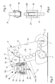
- a new feature is a transport device 18, which extends parallel to the cylinder axis 17 of the pressing chamber 10 arranged guides 19 directly from the side of the roller baler in front of the wrapping device 11 is slidable.
- the transport device 18 and the guides 19 can also be the unchanged Place arranged container 15 immediately upstream as a storage station 13a for a supply roll 14a 2, or it can be used instead of a container 15 and one Transport device 18 and two transport devices arranged side by side or one above the other his.
- the guides 19 have a trapezoidal cross section, as can be seen in FIG. 3, are in one Distance arranged parallel to one another, which is larger than the diameter of the material web roll 14 and are supported by the support bracket 20 on the drawbar 3 and on the front housing 6.
- the guides 19 are angled downward by approximately 45 ° and connected by an angle iron 21, the free legs of which point upwards, around a holding edge 22 to load the charging device 18 there.
- each guide 19 has a rectangular shape Recesses 23, which passes through the retaining edge 22 for locking the charging device 18 in the Abroll- 13 or supply station 13a, see. Fig. 4.
- the transport device 18 consists of a rectangular tubular frame, which between them Material web roll 14 receives so that it is supported on two longitudinal tubes 24, 25, which in one lateral distance are arranged in front of each other, which is smaller than the diameter of the Material web roll 14, while the material web roll 14 in the axial direction by one to the Stop attacking end faces 26, 27 is held against slipping.
- the longitudinal tubes 24, 25 are on the insertion side of the transport device 18 is longer than the length of the Material web roll 14 corresponds and connected to each other by a cross tube 28, which simultaneously forms a handle 29.
- both longitudinal tubes 24, 25 are approximately at the level of the end face of the Roll of material roll 14 angled approximately 45 ° upward and have a cross tube 32 at the end as a connection on, which is also designed as a handle.
- Both longitudinal tubes 24, 25 point below the Stop 27 each facing outward, arranged at right angles to the tube outer sides Axle stub 33 with wheels 34 which are arranged so that the transport device 18 according Dashed representation in Fig. 1 in the removed state on the ground for the transport of Roll of material roll 14 can be moved and with the roll of material roll 14 into the unwinding station 13 or supply station 13a can be inserted.
- the function of the transport device 18 is as follows: Is a material web roll 14 in the Roll baler used up, so the transport device 18 from the roll 13 or the Pulled out supply station 13a, drove to the storage location of the material web rolls and there with a Load web roll 14.
- the relatively heavy, bulky material web roll 14 is by means of the in Fig. 1st Transport device 18 shown in dashed lines easily moved to the roller baler on one hand and hung there with its retaining edge 22 in the angle iron 21.
- the transport device 18 is on the handle 32 is moved into an approximately horizontal position and on the guides 19 in the roll-off 13 or storage station 13a pushed.
- auxiliary drives not shown, can also be used. So one serves Transport device 18 on the one hand as a means of transport of the material web roll 14, 14a from its storage location to the roller baler and on the other hand to insert the material web roll 14, 14a into the roll-off 13 or supply station 13a.
Landscapes
- Life Sciences & Earth Sciences (AREA)
- Environmental Sciences (AREA)
- Storage Of Harvested Produce (AREA)
- Organic Low-Molecular-Weight Compounds And Preparation Thereof (AREA)
- Sowing (AREA)
Abstract
Description
- Fig. 1
- eine Vorderansicht auf eine Rollballenpresse mit einer erfindungsgemäßen, in Strichlinie dargestellten Transporteinrichtung - beladen mit einer Materialbahnrolle - während des Transports zur Rollballenpresse und in Volllinie gezeichneter Stellung angehängt an die Rollballenpresse vor dem Einschieben in eine Abrollstation und
- Fig. 2
- eine schematische Teilseitenansicht auf ein Vordergehäuse der Rollballenpresse mit einer Materialbahnrolle in der Abrollstation und mit einer Vorratsrolle auf der Transporteinrichtung in eingeschobener Position in einer Vorratsstation der Rollballenpresse,
- Fig. 3
- eine Führungsschiene im Querschnitt mit aufgesetztem Laufrad der Transporteinrichtung in der Abrollstation und
- Fig. 4
- eine Führungsschiene in Draufsicht mit einer Verriegelungsklinke zum Arretieren der Transporteinrichtung in der Abroll- oder Vorratsstation.
Claims (10)
- Rollballenpresse für landwirtschaftliche Halmgüter mit einer Ladeeinrichtung für eine Materialbahnrolle (14), gekennzeichnet durch eine leicht von der Rollballenpresse abnehmbare und leicht an die Rollballenpresse anhängbare Transporteinrichtung (18) für die Materialbahnrolle (14, 14a).
- Rollballenpresse nach Anspruch 1, dadurch gekennzeichnet, dass die Transporteinrichtung (18) fahrbar ausgestaltet ist.
- Rollballenpresse nach Anspruch 1, dadurch gekennzeichnet, dass im einschubseitigen Bereich der Seitenwand (8) der Rollballenpresse eine Halterung (21) für die Transporteinrichtung (18) vorgesehen ist.
- Rollballenpresse nach einem der vorhergehenden Ansprüche, dadurch gekennzeichnet, dass die Transporteinrichtung (18) als Tragelement (24, 25, 28, 32) für die Materialbahnrolle (14, 14a) ausgebildet ist und Mittel (26, 27) vorgesehen sind, welche die Materialbahnrolle (14, 14a) wenigstens an den Stirnseiten gegen Wegrutschen in axialer Richtung halten.
- Rollballenpresse nach einem der vorhergehenden Ansprüche, dadurch gekennzeichnet, dass die Transporteinrichtung (18) wenigstens einen Handgriff (29, 32) und Laufräder (34) aufweist.
- Rollballenpresse nach einem der vorhergehenden Ansprüche, dadurch gekennzeichnet, dass nur die Materialbahnrolle (14, 14 a) von der Transporteinrichtung (18) in eine Abroll- (13) und/oder Vorratsstation (13a) überführbar ist.
- Rollballenpresse nach einem der vorhergehenden Ansprüche 1 bis 5, dadurch gekennzeichnet, dass die Materialbahnrolle (14, 14a) zusammen mit der Transporteinrichtung in die Abroll- (13) oder Vorratsstation (13a) bewegbar ist.
- Rollballenpresse nach Anspruch 7, dadurch gekennzeichnet, dass Führungen (19) zum Verschieben der Transporteinrichtung (18) in der Rollballenpresse vorgesehen sind.
- Rollballenpresse nach einem der vorhergehenden Ansprüche, dadurch gekennzeichnet, dass Hilfsantriebe vorgesehen sind, um die Transporteinrichtung aus einer geneigten Position in eine horizontale Position anzuheben.
- Rollballenpresse nach einem der vorhergehenden Ansprüche, dadurch gekennzeichnet, dass Hilfsantriebe vorgesehen sind zum Einschieben der Materialrolle (14, 14a) und/oder der Transporteinrichtung (18) in die Abroll- (13) oder Vorratsstation (13a).
Applications Claiming Priority (2)
| Application Number | Priority Date | Filing Date | Title |
|---|---|---|---|
| DE10004564A DE10004564A1 (de) | 2000-02-02 | 2000-02-02 | Rollballenpresse für landwirtschaftliche Halmgüter |
| DE10004564 | 2000-02-02 |
Publications (3)
| Publication Number | Publication Date |
|---|---|
| EP1129611A2 true EP1129611A2 (de) | 2001-09-05 |
| EP1129611A3 EP1129611A3 (de) | 2002-02-06 |
| EP1129611B1 EP1129611B1 (de) | 2008-07-30 |
Family
ID=7629593
Family Applications (1)
| Application Number | Title | Priority Date | Filing Date |
|---|---|---|---|
| EP01101884A Expired - Lifetime EP1129611B1 (de) | 2000-02-02 | 2001-01-27 | Rollballenpresse für landwirtschaftliche Halmgüter |
Country Status (3)
| Country | Link |
|---|---|
| EP (1) | EP1129611B1 (de) |
| AT (1) | ATE402606T1 (de) |
| DE (2) | DE10004564A1 (de) |
Cited By (4)
| Publication number | Priority date | Publication date | Assignee | Title |
|---|---|---|---|---|
| US10820527B2 (en) | 2018-07-13 | 2020-11-03 | Deere & Company | Baler with netwrap roll loading device |
| US10934143B2 (en) | 2018-07-13 | 2021-03-02 | Deere & Company | Net wrap lifting device |
| EP4018813A1 (de) * | 2020-12-22 | 2022-06-29 | Pomi Industri ApS | Verfahren und system zum transportieren und platzieren von folienrollen auf einer folienwickelmaschine |
| US12382874B2 (en) | 2021-05-04 | 2025-08-12 | Agco International Gmbh | Baling apparatus |
Families Citing this family (3)
| Publication number | Priority date | Publication date | Assignee | Title |
|---|---|---|---|---|
| US8919085B2 (en) | 2011-04-28 | 2014-12-30 | Cnh Industrial America Llc | Net roll support for storage and installation in baler |
| US9320199B2 (en) | 2011-11-22 | 2016-04-26 | Cnh Industrial America Llc | Multiple rolls net wrap assembly |
| NL2014872B1 (en) | 2015-05-28 | 2016-12-30 | Forage Innovations Bv | Wrapping device for wrapping a bale in a bale forming chamber. |
Citations (1)
| Publication number | Priority date | Publication date | Assignee | Title |
|---|---|---|---|---|
| DE19711164A1 (de) | 1997-03-18 | 1998-09-24 | Claas Ohg | Rollballenpresse für landwirtschaftliches Erntegut |
Family Cites Families (4)
| Publication number | Priority date | Publication date | Assignee | Title |
|---|---|---|---|---|
| DE3227160C3 (de) * | 1982-07-21 | 1995-03-23 | Claas Ohg | Rollballen aus landwirtschaftlichem Halmgut |
| US4956959A (en) * | 1989-06-23 | 1990-09-18 | Deere & Company | Housing for holding a supply roll of large round bale wrap material |
| US5181368A (en) * | 1991-12-17 | 1993-01-26 | Deere & Company | Housing for holding a supply roll of large round bale wrap material |
| US5743703A (en) * | 1995-06-20 | 1998-04-28 | Himecs Corp. | Web carrying apparatus |
-
2000
- 2000-02-02 DE DE10004564A patent/DE10004564A1/de not_active Withdrawn
-
2001
- 2001-01-27 DE DE50114159T patent/DE50114159D1/de not_active Expired - Lifetime
- 2001-01-27 AT AT01101884T patent/ATE402606T1/de not_active IP Right Cessation
- 2001-01-27 EP EP01101884A patent/EP1129611B1/de not_active Expired - Lifetime
Patent Citations (1)
| Publication number | Priority date | Publication date | Assignee | Title |
|---|---|---|---|---|
| DE19711164A1 (de) | 1997-03-18 | 1998-09-24 | Claas Ohg | Rollballenpresse für landwirtschaftliches Erntegut |
Cited By (5)
| Publication number | Priority date | Publication date | Assignee | Title |
|---|---|---|---|---|
| US10820527B2 (en) | 2018-07-13 | 2020-11-03 | Deere & Company | Baler with netwrap roll loading device |
| US10934143B2 (en) | 2018-07-13 | 2021-03-02 | Deere & Company | Net wrap lifting device |
| US11299379B2 (en) | 2018-07-13 | 2022-04-12 | Deere & Company | Net wrap lifting device |
| EP4018813A1 (de) * | 2020-12-22 | 2022-06-29 | Pomi Industri ApS | Verfahren und system zum transportieren und platzieren von folienrollen auf einer folienwickelmaschine |
| US12382874B2 (en) | 2021-05-04 | 2025-08-12 | Agco International Gmbh | Baling apparatus |
Also Published As
| Publication number | Publication date |
|---|---|
| DE10004564A1 (de) | 2001-08-09 |
| EP1129611B1 (de) | 2008-07-30 |
| EP1129611A3 (de) | 2002-02-06 |
| ATE402606T1 (de) | 2008-08-15 |
| DE50114159D1 (de) | 2008-09-11 |
Similar Documents
| Publication | Publication Date | Title |
|---|---|---|
| EP1099366B1 (de) | Hüllmittelzufuhrvorrichtung | |
| EP1452086B1 (de) | Vorrichtung zum Pressen und Umwickeln von Rundballen | |
| DE2443838A1 (de) | Rollballenpresse | |
| DE10006384A1 (de) | Rundballenpresse | |
| EP0092077A1 (de) | Antriebsvorrichtung für die Welle einer mobilen Einrichtung | |
| DE102011003727A1 (de) | Rundballenpresse mit seitlichen Führungen für den Pressriemen | |
| EP0935915A1 (de) | Wickelvorrichtung einer Presse mit einer Materialrolle und einer Vorratsrolle | |
| EP0983720A1 (de) | Vorrichtung zum Umwickeln einer Rundballe | |
| DE2448645A1 (de) | Heurollen-formmaschine | |
| DE2530249A1 (de) | Wickelballenpresse | |
| DE3223784A1 (de) | Ausstossmechanismus fuer eine rundballenpresse | |
| EP1186225B1 (de) | Kombination aus einer Presse, einem Wickelgerät und einem diese aufnehmenden Fahrgestell | |
| DE69521457T2 (de) | Ballen-Lade-Wagen um Ballen an eine Wickelvorrichtung abzugeben | |
| EP1121850B1 (de) | Rollballenpresse für landwirtschaftliche Halmgüter | |
| DE2538164B2 (de) | Rundballenpresse für Heu und anderes faseriges Erntegut mit einer Spannvorrichtung für die den Ballen formenden umlaufbaren Bänder | |
| EP1129611B1 (de) | Rollballenpresse für landwirtschaftliche Halmgüter | |
| EP1602270B1 (de) | Rundballenpresse für landwirtschaftliche Halmgüter | |
| DE202005008468U1 (de) | Vorrichtung zum Pressen und Umhüllen von Rundballen | |
| EP2756870A1 (de) | Schlauchaufrollvorrichtung | |
| DE2556234A1 (de) | Kombinierte transport- und aufloesevorrichtung fuer landwirtschaftliche rollballen | |
| DE8213107U1 (de) | Rollballenpresse für landwirtschaftliche Halmgüter mit einer Ballenabrollvorrichtung | |
| DE2419488C2 (de) | Maschine zum Formen von Rundballen | |
| DE69705596T2 (de) | Überziehen von gepresstem Gut mit einer Schlauchfolie | |
| DE1297528B (de) | Vorrichtung zum Pressen und Binden von gruppenweise koaxial nebeneinander gelegten Walzdrahtbunden | |
| DE102005015225A1 (de) | Ladevorrichtung |
Legal Events
| Date | Code | Title | Description |
|---|---|---|---|
| PUAI | Public reference made under article 153(3) epc to a published international application that has entered the european phase |
Free format text: ORIGINAL CODE: 0009012 |
|
| AK | Designated contracting states |
Kind code of ref document: A2 Designated state(s): AT BE CH CY DE DK ES FI FR GB GR IE IT LI LU MC NL PT SE TR Kind code of ref document: A2 Designated state(s): AT DE FR GB IT NL |
|
| AX | Request for extension of the european patent |
Free format text: AL;LT;LV;MK;RO;SI |
|
| PUAL | Search report despatched |
Free format text: ORIGINAL CODE: 0009013 |
|
| AK | Designated contracting states |
Kind code of ref document: A3 Designated state(s): AT BE CH CY DE DK ES FI FR GB GR IE IT LI LU MC NL PT SE TR |
|
| AX | Request for extension of the european patent |
Free format text: AL;LT;LV;MK;RO;SI |
|
| RAP1 | Party data changed (applicant data changed or rights of an application transferred) |
Owner name: LELY MASCHINENFABRIK GMBH |
|
| 17P | Request for examination filed |
Effective date: 20020806 |
|
| AKX | Designation fees paid |
Free format text: AT DE FR GB IT NL |
|
| RAP1 | Party data changed (applicant data changed or rights of an application transferred) |
Owner name: WELGER MASCHINENFABRIK GMBH |
|
| 17Q | First examination report despatched |
Effective date: 20060712 |
|
| GRAP | Despatch of communication of intention to grant a patent |
Free format text: ORIGINAL CODE: EPIDOSNIGR1 |
|
| GRAS | Grant fee paid |
Free format text: ORIGINAL CODE: EPIDOSNIGR3 |
|
| GRAA | (expected) grant |
Free format text: ORIGINAL CODE: 0009210 |
|
| AK | Designated contracting states |
Kind code of ref document: B1 Designated state(s): AT DE FR GB IT NL |
|
| REG | Reference to a national code |
Ref country code: GB Ref legal event code: FG4D Free format text: NOT ENGLISH |
|
| REF | Corresponds to: |
Ref document number: 50114159 Country of ref document: DE Date of ref document: 20080911 Kind code of ref document: P |
|
| PG25 | Lapsed in a contracting state [announced via postgrant information from national office to epo] |
Ref country code: NL Free format text: LAPSE BECAUSE OF FAILURE TO SUBMIT A TRANSLATION OF THE DESCRIPTION OR TO PAY THE FEE WITHIN THE PRESCRIBED TIME-LIMIT Effective date: 20080730 |
|
| PLBE | No opposition filed within time limit |
Free format text: ORIGINAL CODE: 0009261 |
|
| STAA | Information on the status of an ep patent application or granted ep patent |
Free format text: STATUS: NO OPPOSITION FILED WITHIN TIME LIMIT |
|
| 26N | No opposition filed |
Effective date: 20090506 |
|
| PG25 | Lapsed in a contracting state [announced via postgrant information from national office to epo] |
Ref country code: IT Free format text: LAPSE BECAUSE OF FAILURE TO SUBMIT A TRANSLATION OF THE DESCRIPTION OR TO PAY THE FEE WITHIN THE PRESCRIBED TIME-LIMIT Effective date: 20080730 |
|
| PG25 | Lapsed in a contracting state [announced via postgrant information from national office to epo] |
Ref country code: AT Free format text: LAPSE BECAUSE OF NON-PAYMENT OF DUE FEES Effective date: 20090127 |
|
| REG | Reference to a national code |
Ref country code: FR Ref legal event code: CD Owner name: LELY VERMEER MASCHINENFABRIK GMBH, DE Effective date: 20140507 |
|
| REG | Reference to a national code |
Ref country code: DE Ref legal event code: R081 Ref document number: 50114159 Country of ref document: DE Owner name: LELY VERMEER MASCHINENFABRIK GMBH, DE Free format text: FORMER OWNER: WELGER MASCHINENFABRIK GMBH, 38304 WOLFENBUETTEL, DE Effective date: 20140502 Ref country code: DE Ref legal event code: R081 Ref document number: 50114159 Country of ref document: DE Owner name: LELY MASCHINENFABRIK GMBH, DE Free format text: FORMER OWNER: WELGER MASCHINENFABRIK GMBH, 38304 WOLFENBUETTEL, DE Effective date: 20140502 Ref country code: DE Ref legal event code: R081 Ref document number: 50114159 Country of ref document: DE Owner name: FORAGE COMPANY B.V., NL Free format text: FORMER OWNER: WELGER MASCHINENFABRIK GMBH, 38304 WOLFENBUETTEL, DE Effective date: 20140502 |
|
| PGFP | Annual fee paid to national office [announced via postgrant information from national office to epo] |
Ref country code: GB Payment date: 20150127 Year of fee payment: 15 |
|
| REG | Reference to a national code |
Ref country code: FR Ref legal event code: PLFP Year of fee payment: 16 |
|
| GBPC | Gb: european patent ceased through non-payment of renewal fee |
Effective date: 20160127 |
|
| PG25 | Lapsed in a contracting state [announced via postgrant information from national office to epo] |
Ref country code: GB Free format text: LAPSE BECAUSE OF NON-PAYMENT OF DUE FEES Effective date: 20160127 |
|
| REG | Reference to a national code |
Ref country code: FR Ref legal event code: PLFP Year of fee payment: 17 |
|
| REG | Reference to a national code |
Ref country code: DE Ref legal event code: R081 Ref document number: 50114159 Country of ref document: DE Owner name: LELY MASCHINENFABRIK GMBH, DE Free format text: FORMER OWNER: LELY VERMEER MASCHINENFABRIK GMBH, 38304 WOLFENBUETTEL, DE Ref country code: DE Ref legal event code: R081 Ref document number: 50114159 Country of ref document: DE Owner name: FORAGE COMPANY B.V., NL Free format text: FORMER OWNER: LELY VERMEER MASCHINENFABRIK GMBH, 38304 WOLFENBUETTEL, DE |
|
| PGFP | Annual fee paid to national office [announced via postgrant information from national office to epo] |
Ref country code: DE Payment date: 20170125 Year of fee payment: 17 Ref country code: FR Payment date: 20170125 Year of fee payment: 17 |
|
| REG | Reference to a national code |
Ref country code: DE Ref legal event code: R081 Ref document number: 50114159 Country of ref document: DE Owner name: FORAGE COMPANY B.V., NL Free format text: FORMER OWNER: LELY MASCHINENFABRIK GMBH, 38304 WOLFENBUETTEL, DE |
|
| REG | Reference to a national code |
Ref country code: DE Ref legal event code: R119 Ref document number: 50114159 Country of ref document: DE |
|
| PG25 | Lapsed in a contracting state [announced via postgrant information from national office to epo] |
Ref country code: DE Free format text: LAPSE BECAUSE OF NON-PAYMENT OF DUE FEES Effective date: 20180801 Ref country code: FR Free format text: LAPSE BECAUSE OF NON-PAYMENT OF DUE FEES Effective date: 20180131 |
|
| REG | Reference to a national code |
Ref country code: FR Ref legal event code: ST Effective date: 20180928 |