EP1129613A1 - Rail pour la construction d'une serre en feuilles - Google Patents
Rail pour la construction d'une serre en feuilles Download PDFInfo
- Publication number
- EP1129613A1 EP1129613A1 EP00103475A EP00103475A EP1129613A1 EP 1129613 A1 EP1129613 A1 EP 1129613A1 EP 00103475 A EP00103475 A EP 00103475A EP 00103475 A EP00103475 A EP 00103475A EP 1129613 A1 EP1129613 A1 EP 1129613A1
- Authority
- EP
- European Patent Office
- Prior art keywords
- film
- bar
- groove
- strip
- area
- Prior art date
- Legal status (The legal status is an assumption and is not a legal conclusion. Google has not performed a legal analysis and makes no representation as to the accuracy of the status listed.)
- Withdrawn
Links
- 239000011888 foil Substances 0.000 title claims description 27
- 238000010276 construction Methods 0.000 title claims description 7
- 239000004744 fabric Substances 0.000 claims abstract description 10
- XAGFODPZIPBFFR-UHFFFAOYSA-N aluminium Chemical compound [Al] XAGFODPZIPBFFR-UHFFFAOYSA-N 0.000 claims abstract description 3
- 229910052782 aluminium Inorganic materials 0.000 claims abstract description 3
- 229920003023 plastic Polymers 0.000 claims abstract description 3
- 238000007789 sealing Methods 0.000 claims description 16
- 238000009434 installation Methods 0.000 claims description 9
- 238000000465 moulding Methods 0.000 claims 1
- 238000009423 ventilation Methods 0.000 description 36
- 241000238631 Hexapoda Species 0.000 description 8
- 239000011230 binding agent Substances 0.000 description 7
- 238000005516 engineering process Methods 0.000 description 3
- 230000000694 effects Effects 0.000 description 2
- 230000006641 stabilisation Effects 0.000 description 2
- 238000011105 stabilization Methods 0.000 description 2
- XLYOFNOQVPJJNP-UHFFFAOYSA-N water Substances O XLYOFNOQVPJJNP-UHFFFAOYSA-N 0.000 description 2
- 238000006243 chemical reaction Methods 0.000 description 1
- 230000001419 dependent effect Effects 0.000 description 1
- 229920002457 flexible plastic Polymers 0.000 description 1
- 238000009413 insulation Methods 0.000 description 1
- 239000000463 material Substances 0.000 description 1
- 238000005096 rolling process Methods 0.000 description 1
- 239000007787 solid Substances 0.000 description 1
Images


Classifications
-
- A—HUMAN NECESSITIES
- A01—AGRICULTURE; FORESTRY; ANIMAL HUSBANDRY; HUNTING; TRAPPING; FISHING
- A01G—HORTICULTURE; CULTIVATION OF VEGETABLES, FLOWERS, RICE, FRUIT, VINES, HOPS OR SEAWEED; FORESTRY; WATERING
- A01G9/00—Cultivation in receptacles, forcing-frames or greenhouses; Edging for beds, lawn or the like
- A01G9/14—Greenhouses
- A01G9/1407—Greenhouses of flexible synthetic material
- A01G9/1415—Greenhouses of flexible synthetic material with double or multiple walls
-
- Y—GENERAL TAGGING OF NEW TECHNOLOGICAL DEVELOPMENTS; GENERAL TAGGING OF CROSS-SECTIONAL TECHNOLOGIES SPANNING OVER SEVERAL SECTIONS OF THE IPC; TECHNICAL SUBJECTS COVERED BY FORMER USPC CROSS-REFERENCE ART COLLECTIONS [XRACs] AND DIGESTS
- Y02—TECHNOLOGIES OR APPLICATIONS FOR MITIGATION OR ADAPTATION AGAINST CLIMATE CHANGE
- Y02A—TECHNOLOGIES FOR ADAPTATION TO CLIMATE CHANGE
- Y02A40/00—Adaptation technologies in agriculture, forestry, livestock or agroalimentary production
- Y02A40/10—Adaptation technologies in agriculture, forestry, livestock or agroalimentary production in agriculture
- Y02A40/25—Greenhouse technology, e.g. cooling systems therefor
Definitions
- the invention relates to a bar for film house construction according to the preamble of the independent claim.
- Foil houses for example, are called greenhouses used. They have a structure that is general is built from solid strips. Are on the support structure Foils or the like attached to the flat Form weather protection. Vertical supports, so-called “Binder”, bear crossbars attached to them, gutters and similar. Above it rests the roof, the inclination of which Drainage of water or sliding of snow causes.
- a bar previously used by Götsch & Dolschle is for use below the eaves edge of the film house designed.
- the eaves edge is the edge between vertical Sidewall and sloping roof area.
- the bar is a hollow profile that goes vertically down from the eaves edge is attached spaced. The vertical spacing is done to prevent snow from slipping into the gutter in winter to prevent. Because the gutter after is spaced below, snow may slip or up to one certain extent across the gutter.
- the strip has a clamping chamber at the top with which the lower edge the foil forming the sloping roof is attached to the bar can be. In addition, it has a hollow structure to give the bar stability.
- the strip works together with a separate ventilation strip.
- the ventilation strip is also a transverse one Ledge covering the top edge of the film side wall of the film house (Greenhouse) forms.
- the ventilation strip can, for example through a cable mechanism to below discussed bar can be pulled. Then she pulls in her pinched side wall film with high, so that the side wall closed is. If ventilation is desired, can the ventilation bar can be lowered so that in the upper area the side wall has an opening for ventilation arises.
- the object of the invention is to provide a bar for film house construction specify the application of foils for ventilation of the film house allowed from the floor.
- a strip according to the invention for film house construction has a groove running in the longitudinal direction of the bar on the for attaching a first film or a first fabric is designed, wherein the film or fabric covered on the installation position of the bar away from it runs when appropriate.
- the bar can have a further groove, for example a clamping chamber to which another film is attached can, based on the installation position of the bar across or diagonally upwards or vertically upwards from the bar runs away when it is attached.
- the first groove is preferably on the bar in the lower area (lower Half)
- the second groove on the bar is preferably in upper area (upper half).
- the bar described is thus used to attach a Foil for a foil wall that goes down from the bar runs. It can be gathered from below, for example accordion-like or by rolling up, so that from below along the length of the side wall Slot of any height can be generated, so that too the ventilation conditions can be set appropriately.
- the bar can also interact with the one already described Ventilation strip can be designed. Then it is for variable use for different ventilation technologies suitable. When a film is inserted into the first groove is, this can be rolled up from below, so that there is a ventilation slot at the bottom along the floor. If the described first groove is not used, however, can Interact with the ventilation strip so that by lowering a ventilation slot from the bar downward results.
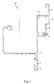
- Fig. 1 shows the profile of an embodiment according to the invention a strip 10.
- the profile of the strip is preferred homogeneous, i.e. it does not change along the length the bar.
- the bar is used for film house construction and in particular greenhouse construction. It can be a hollow profile which has, for example, aluminum and / or plastic.
- Individual strips 10 can have lengths of, for example, 6 m to have. They can be connected to one another using suitable connectors be joined at the joint so that any length of greenhouse can be covered.
- the bar can turn on or below the eaves edge of the greenhouse / foil house are located.
- the profile has a first groove 1 or 3.
- groove 1, 3 a film or a fabric can be attached.
- the groove can be a welt groove (drawn at reference number 3), in which is pressed into a keder cord, which is firmly attached to a Foil can be welded. It may be the groove also act as a clamping chamber 1, into which the film by means a clamping body is clamped. More details on this will be described with reference to FIG. 4.
- the first groove 1, 3 can be in the lower half of the strip 10 or be provided at the bottom of the bar 10.
- a second groove 2 can be provided, on the one second film 12 (see Fig. 2) is attachable.
- the second Groove 2 can also be in the longitudinal direction of the bar extending clamping chamber.
- the second slide can, if it is built in, horizontally or more vertically than horizontally extend. In particular, it can also be vertical run until they start from the second groove 2 Eaves edge has reached. From there it runs at an angle above to the ridge of the roof of the film house.
- the second Groove 2 can be in the upper half of the bar 10 or above be intended for her.
- the profile 10 has an area which is open at the top 4 on. It is a gutter, which absorbs the water running down from the roof and controlled laxation. In the vertical direction, the open area or the gutter 4 between the first groove 1, 3 (bottom) and second groove 2 (top). In horizontal Direction, the central area of the gutter 4 can continue are outside as the first groove 1, 3 and / or the second groove 2.
- the groove in the top left of the profile of the gutter 4 is used Stabilization of the side wall or the entire profile.
- the strip 10 may have a third groove 1, 3, which are provided in addition to the first groove 1, 3 is.
- the third groove is used to hold one down running foil or a downward running fabric.
- both first and third grooves can, for example, a closed film in one be attached. It can be a double-walled film or a bubble film (with individual air chambers). This film can be in a welt groove 3 or by means of a Clamping body in the clamping chamber 1 are attached.
- the other of the two grooves 1, 3 can be, for example Tissues are attached, especially an insect screen fabric or grid. It can be Saran fabric.
- the two grooves 1, 3 can (as shown in Fig. 1) vertically be attached spaced apart.
- the one designed as a clamping chamber can Groove 1 should also be open on the inside.
- a welt groove 3 can also be open to the side.
- the bar has a first area 5 for fastening the List on a support structure of the film house.
- a so-called binder 14 are attached.
- the attachment can be done by screwing.
- the first area 5 can be a vertical section in profile that is as wide as possible is inside. It can, as shown in Fig. 1, in Profile of the bar in the upper half or above.
- the first area 5 can be a closed wall Chamber 9 of the profile.
- the first area 5 can also be a wall of the second groove 2.
- the inner wall of the gutter 4 can also be a wall of the closed Chamber 9 of the profile.
- the inside wall of the gutter 4 can be an opposite one with respect to the chamber 9 Wall to the wall that forms the first area 5.
- the profile can have a second region 6, which is below is the first area 5 and laterally against this is offset.
- the lateral offset can be 5 mm or more.
- the second area 6 extends downwards.
- the vertical extension can be at least 1.5 cm, preferably be at least 2.5 cm.
- the second area 6 can System or attachment of a sealing lip 8 can be designed.
- Fig. 1 shows an embodiment in which in the second area 6 a sealing lip 8 is provided. It is about for example, a flexible plastic material that in a guide in the profile of the bar 10 is pressed.
- the purpose of the second area 6 is referred to Fig. 2b explained.
- the strip 10 can also have a contact area 7 Have contact of a film lip 18a.
- a contact area 7 Preferably lies the investment area 7 under the first area 5 or below the second area 6. It can be against the first area 5 and also against the second area 6 in the horizontal direction be offset. The horizontal offset can be opposite the first area 5 is 2 cm or more.
- the investment area can run downwards or vertically. Its vertical extension can be 4 cm or more, preferably 6 cm or more.
- the contact area 7 can be a wall of the form the first and / or the third groove 1, 3. Preferably it then forms an inner wall of this groove.
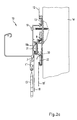
- Fig. 2a shows a first type of use of those designated in Fig. 1 Bar 10.
- 14 denotes a vertically extending support or truss Foil house.
- the bar 10 is, for example attached by screws 19.
- Over the side wall of a greenhouse For example, a binder can be distributed every 2 m 14 stand.
- One screw 19 for the binder Bar 10 may be provided. If a bar is 10 6 m long it would span three trusses.
- the top is by means of a clamping body 15 in the as a clamping chamber laid out second groove a film 12 clamped. She runs up to the eaves edge and from there at an angle up to the ridge.
- a film 13 and a network 11 attached 13 can for example be a keder studded film that is in the top of the keder groove 3 is attached and the bottom from the bottom by one suitable mechanism, not shown, rolled up can be, so that there is a ventilation slot on the bottom results.
- 11 denotes another film or Grid, for example an insect screen, which in the groove 1 designed as a clamping chamber by means of a clamping body 16 is jammed. This results in a combination from fixed insect screen 11 and from below roll-up foil wall 13.
- FIG. 2b shows a further use of the bar 10, which, regardless of or in whole or in part, combined with the use from Fig. 2a is possible.
- bar 10 is another bar 20, which is already at the beginning so-called ventilation profile mentioned and shown in FIG. 4, intended. It can be moved vertically. It can be done by one Mechanism (not shown), for example a cable mechanism, from the floor up to the position shown to be pulled. It can be in any vertical Be held in position.
- the profile has two grooves 21, 22, into each of which films can be clamped.
- With the ventilation profile 20, which is on the outside of the Binders 14 runs, so that one or more films from are pulled upwards. If the profile 20 completely Above as shown in Fig. 2b, the side wall is closed. If, on the other hand, it is lowered, the result is Slit in the side wall that extends from the bar 10 extends downward.
- 2b shows the sealing lip 8, which on a contact area of the ventilation profile 20 is present. This results in the tight fit between profile 10 and ventilation profile 20 and thus an overall tight side wall of the film house. Overall, however, it should be noted that the film lengths themselves due to different temperatures and thus change associated with different thermal expansions can. The difference in length can be a few centimeters depending on whether, for example, -10 ° or + 20 ° to rule. It is therefore desirable that the sealing lip 8 from the side on a vertical, itself in a vertical Area of the sealing profile 20, so that due to the vertical extension of this Range of different lengths of the foils caught can be.
- 2b shows an embodiment in which the sealing lip 8 is attached to the profile 10 and on one vertical area of the ventilation profile 20 is present. The ratios can also be chosen the other way around.
- the Profile 10 then has no sealing lip in the second area 6 8 on. The second area 6 is only for creating one Designed sealing lip that attaches to the ventilation profile 20 is.
- the contact area 7 of the profile 10 on the inside the profile is provided with a film lip 18a a film 18 cooperate as shown.
- the foil lip 18a bears against the contact area 7 and thus has a similar effect like the sealing lip 8.
- the advantage will be noticeable especially in the case of extreme temperature fluctuations. If, for example, due to extremely low temperatures the slides have been shortened considerably, it may be that the contact area of the ventilation strip 20, the sealing lip 8 in Profile 10 no longer reached. If the investment area 7 is sufficiently large, it will still be reached by the film lip 18a, so that despite missing Function of the sealing lip 8 is still a seal.
- a partial one Combination can look like that in the first An insect screen is clamped in the groove of the profile 10 (insect screen 11 and clamping body 16 in Fig. 2a), while a movable foil wall using a ventilation profile 20 is moved or held.
- FIG. 2c shows a further combined mode of use.
- two films 18, 18 'clamped by means of the ventilation profile can be lowered.
- Another slide 13 is attached to the first groove 3 of the strip 10, in the shown Embodiment using a welt.
- the film 13 can be an insulating film, for example around a bubble wrap.
- the film 13 can be double-walled and with be fixed air chambers equipped. The usage can be done here so that the attached to the bar 10 Foil is permanently rolled up during summer it is lowered in winter and so becomes a good one thermal insulation and thus contributes to energy saving. For the sake of completeness it is independent of the level described connection to the modified in Fig. 2c groove 1 'shown.
- the film 13 to rolled up under the bar 10 and the ventilation profile 20 according to the desired opening in the wall under the resulting roll 33 of the film 13 can be lowered. If the film 13 would not be rolled up as far as possible accordingly the ventilation profile 20 and thus the foils 18, 18 'to lower further.
- 3a shows the use of the strip 10 according to FIG. 2a.
- 31 is the ground, 32 indicates plants, 14 are (not Binder to scale.
- 35 symbolizes the Eaves edge. It can be formed by a round profile over which the film is redirected (above the Eaves edge 35 obliquely upwards to the roof ridge (not shown), below the eaves edge 35 more or less vertical down to the bar 10). The distance between the eaves edge 35 and bar 10 can be 50 cm or less.
- the bar 10 extends downwards Slide 13, but from the bottom 31 away from the top is rolled up. Halfway up the roll 33 is rolled up Slide 13 held. Over the entire height of the side wall away, for example, the insect screen 11 lie.
- 36 denotes joints on which individual strips meet and mechanically using a connector and are functionally linked.
- FIG. 3b shows the way in which the strip 10 according to FIG. 2 B.
- the binders 14 stand on the ground 31.
- the vent profile 20 is through a mechanism (not shown) lowered and is kept at a certain height. From the ventilation strip 20 extends downwards the film 18 on the floor outside the truss 14 rests on the accordion.
- an insect screen for example 11 may be provided that in the first groove 1 is attached.
- the strip 10 total height> 12 cm and / or ⁇ 25 cm, preferably between 15 and 20 cm, total width ⁇ 20 cm and / or> 8 cm, preferably between 10 and 15 cm, width of the gutter between 6 and 12 cm, width the chamber 9 between 2 and 4 cm, the height of the chamber 9 between 3 and 7 cm, vertical dimension of the first area 5 > 1.5 cm and / or ⁇ 3 cm.
- Fig. 4 shows a ventilation strip 20, as seen from the EP 0 331 810 B1 is known. It is described here because the principle of the clamping chamber also used in the bar 10 can be.
- the profile 20 has two clamping chambers 21, 22 on. It has a closed chamber 41 for stabilization of the profile over its length.
- a Clamping chamber (e.g. 22) has end walls 43 and 44, one closed side wall 42 and a partially open side wall 45 on.
- the end wall facing the outgoing film 44 can be rounded or semicircular at least on the inside his.
- the partially open side wall 45 can be a first Have approach 45, the one facing the outgoing film End wall 44 attaches.
- On the other end wall 43 a second approach 49 can be provided.
- the film is fastened by means of a clamping body 47 pressed into the groove 22 or clamping chamber 22.
- the clamping body is dimensioned so that it is in the clamping chamber 22 can be inserted. He then pushes the film 46 in this into it.
- the length of the film is such that it the clamp body along the first approach 45, the rounded End wall 44, the closed side wall 42, the End wall 43 and the second approach 49 surrounds. It can then a film lip 46a protrude, which if appropriate Dimensioning of the film lip 46a or attachment the groove or clamp chamber 22 for further sealing as referring described on Fig. 2b can serve.
- a clamping chamber 1, 3 or 2 (groove 1 to 3) of the profile 10 can be constructed like the clamping chamber just described.
- Typical or preferred dimensions of the ventilation profile 20 or a clamping chamber can be individually as follows:
- the vertical dimension of the clamping body 47 results from the vertical dimension of the clamping chamber (internal dimension) reduced by the measure of the second approach 49.
- a film house wall can be designed so that whose lower edge is vertically movable.
- the top edge of one or more of the films of the film house wall can then for example one designed as described above Profile 10 are held. It can all slides or just individual foils of the wall on its lower edge be agile.
- the wall can be more or less vertical run. It can be the vertical side wall or a part of it, or it can be part of the roof.
- the wall area, whose at least one film is away from below is movable, can be built on the inside or outside of the slide house to be built lie.
Landscapes
- Life Sciences & Earth Sciences (AREA)
- Environmental Sciences (AREA)
- Greenhouses (AREA)
Priority Applications (1)
| Application Number | Priority Date | Filing Date | Title |
|---|---|---|---|
| EP00103475A EP1129613A1 (fr) | 2000-03-01 | 2000-03-01 | Rail pour la construction d'une serre en feuilles |
Applications Claiming Priority (1)
| Application Number | Priority Date | Filing Date | Title |
|---|---|---|---|
| EP00103475A EP1129613A1 (fr) | 2000-03-01 | 2000-03-01 | Rail pour la construction d'une serre en feuilles |
Publications (1)
| Publication Number | Publication Date |
|---|---|
| EP1129613A1 true EP1129613A1 (fr) | 2001-09-05 |
Family
ID=8167892
Family Applications (1)
| Application Number | Title | Priority Date | Filing Date |
|---|---|---|---|
| EP00103475A Withdrawn EP1129613A1 (fr) | 2000-03-01 | 2000-03-01 | Rail pour la construction d'une serre en feuilles |
Country Status (1)
| Country | Link |
|---|---|
| EP (1) | EP1129613A1 (fr) |
Citations (4)
| Publication number | Priority date | Publication date | Assignee | Title |
|---|---|---|---|---|
| DE2059832A1 (de) * | 1970-12-04 | 1972-06-22 | Lemfoerder Orchideenzucht Erik | Gewaechshaus mit einem Traggeruest und zumindest ueberwiegend durchsichtigen oder durchscheinenden Wand- und/oder Bedachungselementen |
| US4316308A (en) * | 1977-03-28 | 1982-02-23 | Brave Trading Limited | Retaining and stretching element for a film supporting framework |
| EP0331810A1 (fr) * | 1988-03-10 | 1989-09-13 | Friedrich Fälschle | Cadre en profilé |
| WO1993000796A1 (fr) * | 1991-07-05 | 1993-01-21 | Floralink Horticulture Limited | Systeme de construction de structures a toiture telles que les serres |
-
2000
- 2000-03-01 EP EP00103475A patent/EP1129613A1/fr not_active Withdrawn
Patent Citations (4)
| Publication number | Priority date | Publication date | Assignee | Title |
|---|---|---|---|---|
| DE2059832A1 (de) * | 1970-12-04 | 1972-06-22 | Lemfoerder Orchideenzucht Erik | Gewaechshaus mit einem Traggeruest und zumindest ueberwiegend durchsichtigen oder durchscheinenden Wand- und/oder Bedachungselementen |
| US4316308A (en) * | 1977-03-28 | 1982-02-23 | Brave Trading Limited | Retaining and stretching element for a film supporting framework |
| EP0331810A1 (fr) * | 1988-03-10 | 1989-09-13 | Friedrich Fälschle | Cadre en profilé |
| WO1993000796A1 (fr) * | 1991-07-05 | 1993-01-21 | Floralink Horticulture Limited | Systeme de construction de structures a toiture telles que les serres |
Similar Documents
| Publication | Publication Date | Title |
|---|---|---|
| DE69725421T2 (de) | Gewächshausdach | |
| DE3431208A1 (de) | Dachbelueftungsfuehrung | |
| DE102007053373A1 (de) | Befestigungsbügel | |
| DE202018106248U1 (de) | Eindeckteil für ein Dachelement, wie z. B. ein Dachfenster, und Eindecksatz | |
| DE4429457A1 (de) | Rinnenkörper | |
| DE19708130C2 (de) | Traufenabschlußelement | |
| DE69309756T2 (de) | Anschlusselement für Bauprofile und Konstruktionen, die mittels solcher Anschlusselemente verbundene Bauprofile enthalten | |
| DE69000195T2 (de) | Lattenvorrichtung, insbesondere fuer ueberdeckung von geneigten daechern. | |
| DE69920327T2 (de) | Bedachung aus gefaltetem Metallblech | |
| DE8531994U1 (de) | Eindeckrahmen für Dachfenster | |
| DE29511369U1 (de) | Führungsleiste zur Befestigung von Dachzubehörteilen | |
| DE102016007242B4 (de) | Vorrichtung zum Abdecken des äußeren Bereichs der unteren Begrenzung einer Gebäudeöffnung | |
| EP0786568B1 (fr) | Elément d'aération pour toitures | |
| EP1129613A1 (fr) | Rail pour la construction d'une serre en feuilles | |
| DE102007053376B4 (de) | Befestigungsbügel | |
| EP2439464A2 (fr) | Profilé d'insertion pour le montage de profilés de retenue pour modules sous forme de plaques et cadre en plusieurs parties comprenant celui-ci | |
| DE2950045C2 (de) | Dacheindeckungsplatte mit Wärmeleitblech | |
| EP0495805B1 (fr) | Ventilation faitiere | |
| EP0863271A2 (fr) | Recouvrement de noue de toiture | |
| DE102012025362B4 (de) | Firstprofilelement für ein Satteldach und Verfahren zum Montieren eines Satteldachs | |
| DE20020354U1 (de) | Bausatz für ein Gartenhaus | |
| DE29611015U1 (de) | Traufenabschlußelement | |
| DE7623676U1 (de) | Umsetzbare, transparente, tunnelfoermige abdeckhaube | |
| DE29614812U1 (de) | Befestigungsvorrichtung | |
| EP2372049A1 (fr) | Pavillon transportable doté d'un rigole d'écoulement |
Legal Events
| Date | Code | Title | Description |
|---|---|---|---|
| PUAI | Public reference made under article 153(3) epc to a published international application that has entered the european phase |
Free format text: ORIGINAL CODE: 0009012 |
|
| AK | Designated contracting states |
Kind code of ref document: A1 Designated state(s): AT BE CH CY DE DK ES FI FR GB GR IE IT LI LU MC NL PT SE |
|
| AX | Request for extension of the european patent |
Free format text: AL;LT;LV;MK;RO;SI |
|
| 17P | Request for examination filed |
Effective date: 20020204 |
|
| AKX | Designation fees paid |
Free format text: AT DE |
|
| 17Q | First examination report despatched |
Effective date: 20040730 |
|
| STAA | Information on the status of an ep patent application or granted ep patent |
Free format text: STATUS: THE APPLICATION IS DEEMED TO BE WITHDRAWN |
|
| 18D | Application deemed to be withdrawn |
Effective date: 20051001 |