EP1129650A1 - Dispositif de présentation - Google Patents
Dispositif de présentation Download PDFInfo
- Publication number
- EP1129650A1 EP1129650A1 EP01301270A EP01301270A EP1129650A1 EP 1129650 A1 EP1129650 A1 EP 1129650A1 EP 01301270 A EP01301270 A EP 01301270A EP 01301270 A EP01301270 A EP 01301270A EP 1129650 A1 EP1129650 A1 EP 1129650A1
- Authority
- EP
- European Patent Office
- Prior art keywords
- wall
- display apparatus
- upstanding
- module
- protruding
- Prior art date
- Legal status (The legal status is an assumption and is not a legal conclusion. Google has not performed a legal analysis and makes no representation as to the accuracy of the status listed.)
- Granted
Links
- 230000001419 dependent effect Effects 0.000 claims description 2
- 238000004519 manufacturing process Methods 0.000 description 8
- 239000000463 material Substances 0.000 description 6
- 238000001125 extrusion Methods 0.000 description 4
- 239000004417 polycarbonate Substances 0.000 description 4
- 229920000515 polycarbonate Polymers 0.000 description 4
- NIXOWILDQLNWCW-UHFFFAOYSA-N acrylic acid group Chemical group C(C=C)(=O)O NIXOWILDQLNWCW-UHFFFAOYSA-N 0.000 description 3
- 239000004033 plastic Substances 0.000 description 3
- 229920003023 plastic Polymers 0.000 description 3
- 238000012986 modification Methods 0.000 description 2
- 230000004048 modification Effects 0.000 description 2
- 230000000007 visual effect Effects 0.000 description 2
- 230000015572 biosynthetic process Effects 0.000 description 1
- 238000010276 construction Methods 0.000 description 1
- 238000001816 cooling Methods 0.000 description 1
- 230000001627 detrimental effect Effects 0.000 description 1
- 230000000694 effects Effects 0.000 description 1
- 238000005516 engineering process Methods 0.000 description 1
- 238000003780 insertion Methods 0.000 description 1
- 230000037431 insertion Effects 0.000 description 1
- 230000014759 maintenance of location Effects 0.000 description 1
- 239000002184 metal Substances 0.000 description 1
- 238000000034 method Methods 0.000 description 1
- 238000007639 printing Methods 0.000 description 1
- 238000003860 storage Methods 0.000 description 1
- 238000002604 ultrasonography Methods 0.000 description 1
- 238000003466 welding Methods 0.000 description 1
Images
Classifications
-
- A—HUMAN NECESSITIES
- A47—FURNITURE; DOMESTIC ARTICLES OR APPLIANCES; COFFEE MILLS; SPICE MILLS; SUCTION CLEANERS IN GENERAL
- A47F—SPECIAL FURNITURE, FITTINGS, OR ACCESSORIES FOR SHOPS, STOREHOUSES, BARS, RESTAURANTS OR THE LIKE; PAYING COUNTERS
- A47F7/00—Show stands, hangers, or shelves, adapted for particular articles or materials
- A47F7/14—Show stands, hangers, or shelves, adapted for particular articles or materials for pictures, e.g. in combination with books or seed-bags ; for cards, magazines, newspapers, books or booklike articles, e.g. audio/video cassettes
- A47F7/144—Show stands, hangers, or shelves, adapted for particular articles or materials for pictures, e.g. in combination with books or seed-bags ; for cards, magazines, newspapers, books or booklike articles, e.g. audio/video cassettes the show stands or the like being provided with trays, shelves or adjustable partitioning means therefor
- A47F7/145—Terraced shelves
Definitions
- This invention relates to a display apparatus, in particular but not exclusively for use in retail environments such as shops.
- the display apparatus of the invention may also be used e.g. in banks, hospitals, offices and indeed virtually anywhere that it is required to provide an attractive display of articles.
- EP-A-0 295 869 discloses a display apparatus intended primarily for the displaying of laminar articles such as cards, leaflets, sheets, brochures and magazines.
- EP-A-0 295 869 discloses a plurality of elongate channels, fabricated from a plastics material such as polycarbonate; suspended one below another. Each channel is of generally J-shaped cross section for supporting articles in the trough thereby formed.
- Each J-shaped trough has a longer arm and a shorter arm.
- the apparatus includes a support for supporting each lower J-shaped channel on the next higher J-shaped channel.
- the support includes a hook, which is provided on the longer arm of each lower J-shaped channel and which hooks over the shorter arm of the next higher J-shaped channel whereby each lower J-shaped channel is suspended from the shorter, forward arm of the next higher J-shaped channel so as to provide a suspended tiered display.
- the apparatus of EP-A-0 295 869 may be dismantled for transportation, storage and replacement.
- each lower J-shaped channel is suspended from the shorter arm (i.e. the front arm) of the upwardly adjacent J-shaped channel. This means that, in order to provide a visually attractive display, all the J-shaped channels must have longer and shorter arms of the same respective lengths.
- the formation of the upper end of the longer arm of each J-shaped channel as a hook, that hooks over the shorter arm of the next upwardly adjacent J-shaped channel means that some of the space, between the shorter and longer arms defining the trough for displaying articles, is occupied by the material of the hook. This limits the available distance between the front and rear arms, and hence the quantity of articles that can be displayed in the apparatus of EP-A-0 295 869. This is important when the articles displayed are, e.g. greetings cards.
- the known display It is also known to provide an apparatus (herein “the known display") that defines a cascading series of U-shaped channels. The upper edge of the rear limb of a lower said channel is connected to the underside of the next upwardly adjacent channel.
- the known display also permits the creation of visual effects in the apparatus, that appear not to be possible in the EP-A-0 295 869 apparatus.
- the upper edge of each front wall of each module is free. This in turn means that at least the front wall of the known display may be decorated e.g. by means of the addition of embellishments, or by virtue of having a non-rectilinear upper edge.
- the known display remains readily dismantleable and reassemblable.
- the known display may require modification in order to display tall, flexible, items, such as magazines. This is because the upstanding front wall, of each U-shaped channel, that supports the upper parts of articles in the adjacent lower channel, is not generally tall enough to prevent magazines and similar articles from flopping over in the display. This is of course undesirable since in this condition the advertising effect of the magazine covers may be lost; the magazines may become damaged and unsaleable; and the stocked display is unsightly.
- an apparatus as defined in Claim 1.
- a preferred feature of the shape of the apparatus is defined in Claim 2.
- This apparatus enjoys the same advantages, over the apparatus of EP-A-0 295 869, as the known apparatus. It additionally may be manufactured having dimensions (in particular, a height) suitable for supporting magazines and tall leaflets.
- an apparatus as aforesaid including a further, lower module including a further, lower upstanding wall and a third protruding wall protruding therefrom, the further, lower upstanding wall being connectable, at a point below its uppermost edge, to the second protruding wall whereby, on connection of the third protruding wall and the further, lower, upstanding wall together, a portion of the further, lower, upstanding wall extends above the second protruding wall to define, with the walls of the first, lower module a further said channel, that is open along at least one edge for display and dispensing of articles therein.
- the apparatus includes a plurality of the further lower modules supported one beneath another, by virtue of connection of the upstanding wall of each lower module to the protruding wall of the adjacent, higher module, whereby to define a series of the preferably generally U- or J-shaped modules one beneath another.
- the display apparatus of the invention may be configured as a descending series of virtually any number of receptacles or channels that are suitable for supporting magazines, leaflets or similar articles.
- Claims 5 to 9 define features that permit the ready connecting together, in a tiered display, of more than two of the modules of the apparatus.
- Claim 10 defines a terminating wall that with the lowermost module of the display or recess defines a lowermost U- or J-shaped channel, for displaying more of the magazines or leaflets.
- Claim 11 defines advantageous features of the terminating wall, that permit its ready attachment to the lowermost module of the display.
- Claims 12 to 16 advantageously define means for supporting and bracing the apparatus relative to a fixed, preferably vertical surface such as a wall.
- the upstanding wall of the or each lower module is generally parallel to the upstanding wall of the upwardly adjoining module when the modules are connected together. However, this need not necessarily be so.
- the upstanding walls of the respective modules are of generally equal heights. This allows the manufacture of a standard module size, that may be used to build up a tiered display of virtually any preferred depth.
- a display apparatus may if desired may include a mix of the aforesaid types of module.
- the upstanding wall of a said module may include ornamental features.
- An example of such an ornamental feature is that of a non-rectilinear free edge to the upstanding wall of a module.
- the said upper edge may include cut-outs or recesses to define a preferred image, pattern or message.
- the said front wall to include eg. indicia, embossments, apertures and/or recesses, to enhance the appearance of the display, display a message or for other purposes as disclosed hereinbelow.
- Claim 22 defines a further feature that advantageously assists in the display of thin, laminar items.
- Claim 23 defines a moveable divider for sub-dividing the interior of a said receptacle in more detail.
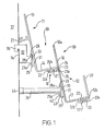
- a modular display apparatus 10 that in its simple form includes upper 11 and lower 12 modules joined together to define the display apparatus 10.
- Upper module 11 includes an upper upstanding wall 13 and, in the embodiment shown, protruding at right angles thereto a first protruding wall 14.
- Protruding wall 14 may in other embodiments protrude at other angles than the right angle shown.
- Lower module 12 is in the embodiment shown identical to upper module 11.
- lower module includes a lower upstanding wall 16 and a second protruding wall 17 protruding at right angles to lower upstanding wall 16.
- Second protruding wall 17 may also protrude at angles other than ninety degrees.
- Lower upstanding wall 16 is connected, at a point 18 on its rear face below its upper, free edge 16a, to the underside of first protruding wall 14.
- the modules 11, 12 define a display apparatus 10 in which the portion of lower upstanding wall 16 protruding above connection 18 defines, with the walls 13, 14 of the upper module 11, a J-shaped channel 19 that is open along at least one edge.
- each upstanding wall 13, 16 and the width of each module 11, 12, in the direction perpendicular to Figure 1 are sufficient, the resulting J-shaped channel 19 is suitable for displaying tall, flexible items, such as magazines, in an attractive way that minimises damage to the articles.
- module 12 is identical to module 11, it includes part of a connector, such as connector 18, in the underside of second protruding wall 17.
- lower upstanding wall may if desired be arranged to extend above the second protruding wall 17 and define, with the walls 16, 17 of module 12, a further J-shaped channel.
- a downwardly extending series of the J-shaped channels may be formed by securing a series of the modules such as modules 11, 12 one beneath another in a manner analogous to the arrangement of modules 11, 12.
- connection 18 The parts of the modules 11, 12 defining the connection 18 will now be described in more detail.
- Connector 18 includes a slot 21 protruding from approximately half way down the rear face of each upstanding wall 13, 16.
- the underside of each protruding wall 14, 17 includes protruding therefrom a pair of members 22, 23 that are form-lockingly engageable with an adjacent slot 21 to connect the modules 11, 12 together.
- both the slot 21 and the members 22, 23 are elongate in the direction perpendicular to the plane of Figure 1, whereby on connection of the modules together each lower module is suspended from the adjacent upper module along most of or all its width.
- the members 22, 23 define an essentially T-section arrangement; and the slot 21 is of a correspondingly sized T-section.
- the members 22, 23 are mutually parallel, elongate, L-section members 22, 23 spaced from one another and protruding downwardly from the undersides of the protruding walls 14, 17 to define the essentially T-section shape. This is achieved by virtue of divergence of the free limbs 22a, 23a of the L-sections from one another as shown.
- the T-slot 21 is constituted by a first top wall 24 protruding at right angles from the rear side of each upstanding wall 14, 17; and, spaced below the first top wall 24, a J-section member 26 whose straight end 26a protrudes at right angles to the said rear side. Consequently the free, curved end 26b of J-section member 26 is juxtaposed to and spaced laterally from the free end of the first top wall 24.
- the members 24, 26 define the T-slot, with the portion of the J-section member 26 adjacent the end 26b defining a second top wall parallel to and spaced from first top wall 24.
- the T-slot is open along its upper side, to accommodate the stems of the L-section members 22, 23.
- the essentially T-section member and the T-slot may be formed in other ways than those described herein. Also it is not essential to employ T-section members and slots to achieve the desired releasable connection between adjacent modules in a display 10. However, the components described herein provide firm support for suspended modules along the active width of a display 10, while also being easy to manufacture by extrusion.
- Module 12 of Figure 1 shows a means of terminating a cascade of the modules 14, 17 defining a display 10. This is through use of an upwardly extending end wall 27 that is secured to the underside of second protruding wall 17. Wall 27 is of comparable width to wall 17 in a direction perpendicular to the plane of Figure 1.
- end wall 27 when secured to second protruding wall 17 extends only slightly lower than the underside of wall 17; whereas the top of wall 27 protrudes above wall 17 by a comparable distance to the extent of protrusion of wall 16 above first protruding wall 14. Consequently end wall 27 defines, with the walls of module 12, a J-shaped channel.
- Wall 27 includes, protruding at right angles to its lowermost end 27a, a T-slot arrangement 121 that in the embodiment shown is of the same construction as T-slot 21 described hereinabove.
- T-slot 121 includes a first top wall 124 and a J-section member 126 arranged analogously to members 24 and 26. Consequently end wall 27 may be slid into engagement along its length with the L-section members 22, 23 extending along the underside of the module requiring termination by means of wall 27.
- end wall 27 is shown secured to the lowermost module of a pair 11, 12 of modules, it may of course be secured, in the manner described, to a display apparatus comprising any number of the modules suspended in a downwardly extending series.
- T-slot 121 of wall 27 may if desired be formed in other ways than the one described. Indeed it is not essential that a T-slot per se be used for securing the end wall 27, numerous functional equivalents to the described T-slot being possible. However, a T-slot of the kind described herein has been found to be particularly suitable for manufacture by extrusion.
- the display apparatus 10 is supported in use as follows:
- each upstanding wall 13, 16 has extending therefrom a pair of L-section members 28, 29 arranged so that a free end 28a of one of the members is juxtaposed to the free end 29a of the other member 29.
- the stem of each member 28, 29 is secured to the upstanding wall 13, 16 as appropriate, whereby the L-section members 28, 29 define a channel 31.
- the L-section members 28, 29 extend perpendicular to the plane of Figure 1 for the width of the display apparatus 10, whereby the channel 31 extends for the same distance.
- a support member 32 having a T-profile head 33 is slideably receivable in the channel 31 of the uppermost module 11 of a plurality of modules defining a display apparatus 10 according to the invention.
- Support member 32 includes spaced rearwardly from channel 31 in use of the apparatus 10 a reaction surface 34; and spaced rearwardly and upwardly from channel 31 a hook 36.
- Hook 36 is dimensioned to fit into eg. a standard size of shopfitting slot formed eg. in a rail 37 secured to a building wall.
- the mass of the lower portion of apparatus 10 is supported by a rod or tube 38 having at one end a T-profile head 39 and at the other end a foot 41.
- T-profile head 39 may be formed, when member 38 is a hollow tube open at at least one end, from a top hat section member, the protruding, cylindrical (non-flanged) part 39a of which is inserted into the open end of the tube 38 as shown in Figure 4.
- cylindrical part 39a has formed protruding therefrom a series of elongate ribs 40 that ensure secure retention of part 39a within tube 38 when the components are pushed together by hand.
- T-profile head 39 is receivable in a channel 31 (described below) to allow member 38 to support the display apparatus and space it from eg. rail 37.
- the stems of the L-section members 28, 29 while parallel to one another, are not perpendicular to the rear face of each upstanding member 13, 16. Also the length of the stem of each lower L-section member 29 is longer than the stem of each upper L-section member 28.
- each channel 31 is of generally triangular profile, thereby permitting suspending of the apparatus 10 in a range of orientations.
- the flange 39b of T-profile head 39 is square in the preferred embodiment shown, to assist sliding of flange 39b into slot 31.
- Slot 31 is open at either end to facilitate insertion of the head 39.
- the angle between the planes of the T-profile heads 33, 39 and the upstanding walls 13, 16 is at a maximum, whereby the apparatus 10 is tilted backwards relative to rail 37.
- This orientation which is ideal for displaying magazines in a retail environment, is achieved by virtue of a downwardly depending lug 42 formed protruding from the rear face of the flange of T-profile head 39.
- Lug 42 includes a wall extending downwardly parallel to the flange of T-profile head 39, whereby the lip 43 of L-section member 29 may be sandwiched, on sliding of T-profile head 39 into channel 31, between wall 42 and the flange of member 39. This ensures that the apparatus does not rotate to an orientation other than that shown.
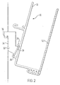
- Figure 2 shows how this may be achieved through use of an elongate version 127, of the same height as upstanding wall 13, of the end wall 27 described hereinabove.
- the upper portions of the lower upstanding walls 16 of the lower modules 12 could if desired be similarly elongate in order to achieve the U-shape channel desired in the forwardly tilted embodiment shown.
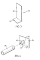
- Figure 3 shows one form of moveable divider 51 that is insertable into the channel defined by the upstanding walls.
- Divider 51 includes a laminar upstand 52 that is connected to a laminar foot member 53 to form a generally L-shaped configuration.
- Divider 51 is dimensioned to fit into the U- or J-shaped channels with the upstand uppermost and the foot member 53 slideably moveable along the bottom of the channel.
- the laminar upstand 52 thus extends upwards, between and generally parallel to the side walls 13 and 16 of the module in which it is positioned.
- the upstand 52 preferably is approximately the same length as the articles (eg. magazines) displayed in the apparatus.
- the modules are manufactured from a material such as polycarbonate or acrylic, which may readily be self-coloured or transparent, depending on the precise requirements for the display.
- each module may easily be manufactured as an elongate extrusion. Consequently, the manufacture of each module is advantageously quick to achieve. Also, through use of per se known extrusion technology, the quality and integrity of the modules may be assured.
- modules are manufactured from acrylic or polycarbonate, they may be fabricated from a series of acrylic or polycarbonate panels that can be welded together, e.g. by heat or ultrasound welding. Alternatively the modules of the invention may be manufactured from other plastics materials, from metal, or even from formable natural materials such as timber.
Landscapes
- Display Racks (AREA)
- Devices For Indicating Variable Information By Combining Individual Elements (AREA)
- Fittings On The Vehicle Exterior For Carrying Loads, And Devices For Holding Or Mounting Articles (AREA)
- Toys (AREA)
- Burglar Alarm Systems (AREA)
Applications Claiming Priority (2)
| Application Number | Priority Date | Filing Date | Title |
|---|---|---|---|
| GB0005115 | 2000-03-03 | ||
| GB0005115A GB2359730B (en) | 2000-03-03 | 2000-03-03 | A display apparatus |
Publications (2)
| Publication Number | Publication Date |
|---|---|
| EP1129650A1 true EP1129650A1 (fr) | 2001-09-05 |
| EP1129650B1 EP1129650B1 (fr) | 2007-05-09 |
Family
ID=9886871
Family Applications (1)
| Application Number | Title | Priority Date | Filing Date |
|---|---|---|---|
| EP01301270A Expired - Lifetime EP1129650B1 (fr) | 2000-03-03 | 2001-02-14 | Dispositif de présentation |
Country Status (7)
| Country | Link |
|---|---|
| US (1) | US6422403B1 (fr) |
| EP (1) | EP1129650B1 (fr) |
| AT (1) | ATE361689T1 (fr) |
| CA (1) | CA2337459A1 (fr) |
| DE (1) | DE60128278T2 (fr) |
| ES (1) | ES2287079T3 (fr) |
| GB (1) | GB2359730B (fr) |
Cited By (1)
| Publication number | Priority date | Publication date | Assignee | Title |
|---|---|---|---|---|
| GB2378121A (en) * | 2001-06-14 | 2003-02-05 | Eml Ltd | A module unit for displaying CD or DVD cases on a shelf |
Families Citing this family (10)
| Publication number | Priority date | Publication date | Assignee | Title |
|---|---|---|---|---|
| GB2351224B (en) * | 1999-06-25 | 2004-03-31 | Eml Ltd | A display apparatus |
| US6942108B2 (en) * | 2002-06-19 | 2005-09-13 | Anderson News Company | Display rack |
| US7775379B2 (en) * | 2006-10-03 | 2010-08-17 | American Greetings Corporation | Retail display for greeting cards |
| US8157109B2 (en) * | 2007-12-12 | 2012-04-17 | Deflecto, LLC | Mountable storage apparatus with retractable linking mechanism and method |
| US7987999B2 (en) * | 2009-01-16 | 2011-08-02 | American Greetings Corporation | Product display highlighter |
| US9451838B2 (en) | 2014-06-20 | 2016-09-27 | Hallmark Cards, Incorporated | Snap-in card top riser |
| US9668593B2 (en) | 2014-06-20 | 2017-06-06 | Hallmark Cards, Incorporated | Modular display tower |
| US10010197B1 (en) * | 2017-05-26 | 2018-07-03 | W.A. Krapf, Inc. | Document holding apparatus |
| US10952550B2 (en) * | 2018-04-09 | 2021-03-23 | American Greetings Corporation | Flexible row count card tier |
| US11291315B2 (en) * | 2020-01-28 | 2022-04-05 | American Greetings Corporation | Greeting card displayer |
Citations (7)
| Publication number | Priority date | Publication date | Assignee | Title |
|---|---|---|---|---|
| US3198340A (en) * | 1963-07-24 | 1965-08-03 | Stephen G Tokash | Extruded display rack riser |
| US3926314A (en) * | 1974-02-08 | 1975-12-16 | Ferrero & C Spa P | Vacuum molded column-type display device for parallelepiped-shaped objects |
| EP0295869A2 (fr) | 1987-06-15 | 1988-12-21 | Forfas | Unité de présentation |
| GB2241155A (en) * | 1990-01-11 | 1991-08-28 | Glazer Plastics Limited | Racking system |
| GB2279554A (en) * | 1993-07-08 | 1995-01-11 | Glazer Plastics Limited | Tiered display systems |
| US5513745A (en) * | 1994-10-26 | 1996-05-07 | Gibson Greetings, Inc. | Shipment and display fixture for greeting cards |
| WO1998054688A1 (fr) * | 1997-05-30 | 1998-12-03 | Checkmate International Pty. Ltd. | Appareil permettant d'exposer des articles |
Family Cites Families (21)
| Publication number | Priority date | Publication date | Assignee | Title |
|---|---|---|---|---|
| DE516656C (de) | 1924-09-09 | 1931-01-26 | Gewerkschaft Wallram | Verfahren zur Herstellung von Gusskoerpern aus Karbiden schwer schmelzbarer Metalle oder Metalloide, z. B. Wolfram |
| DE478143C (de) | 1928-01-20 | 1929-06-18 | Hanseatische Appbau Ges Vorm L | Sammelbriefkastenanlage |
| US2532600A (en) * | 1948-01-19 | 1950-12-05 | Henry T Parker | Display rack |
| US2886182A (en) * | 1956-03-29 | 1959-05-12 | Stamford Metal Specialty Co In | Counter rack |
| DE1911331A1 (de) * | 1969-03-06 | 1970-10-01 | Felix Zock | Fachboden,insbesondere fuer Stufenregale |
| GB1337194A (en) * | 1971-02-17 | 1973-11-14 | Hallmark Cards | Merchandise display unit |
| GB1482997A (en) * | 1975-10-31 | 1977-08-17 | Cooper Ltd P | Display racks for greeting cards records stationery and the like |
| US4149630A (en) | 1977-05-02 | 1979-04-17 | Felix Transport | Collapsible easel support |
| DE8016255U1 (de) | 1980-06-20 | 1980-09-11 | Woeber, Irmfried, Wuermla (Oesterreich) | Behaelter fuer schriftgut, papierwaren o.dgl. |
| GB2121273B (en) | 1982-06-05 | 1986-09-10 | Linvar Ltd | Shelf dividers and clamps |
| US4598504A (en) * | 1983-03-03 | 1986-07-08 | Tamatoshi Industries Ltd. | Wall display structure |
| US4630731A (en) | 1985-02-08 | 1986-12-23 | The Cooperative Marketing Co. | Brochure holder and blank therefor |
| US4613047A (en) * | 1985-03-25 | 1986-09-23 | Hallmark Cards, Incorporated | Small article display assembly |
| DE3542850A1 (de) | 1985-12-04 | 1987-06-11 | Werner Schenk | Verkaufsmoebel und warenfach fuer ein derartiges moebel |
| EP0295859B1 (fr) | 1987-06-15 | 1994-11-17 | Southern Cross Biotech Pty.Ltd. | Préparation de protéines dans les formes actives |
| GB8724686D0 (en) | 1987-10-21 | 1987-11-25 | Johnson B T | Article display apparatus |
| US4796764A (en) | 1987-10-22 | 1989-01-10 | American Greetings Corporation | Divider for merchandise display |
| NL8801136A (nl) * | 1988-05-02 | 1989-12-01 | Robert Gerard Cornelis Jonker | Inrichting voor het uitstallen van platte voorwerpen. |
| GB2244978B (en) | 1990-02-16 | 1994-02-16 | Earley Marketing Ltd | Receptacle and mould for making the same |
| GB2317328B (en) | 1994-08-16 | 1998-12-02 | Barkston Plastics Display Limi | Display apparatus |
| US5938048A (en) | 1994-11-30 | 1999-08-17 | Carroll Products And Designs Limited | Modular tiered rack assembly |
-
2000
- 2000-03-03 GB GB0005115A patent/GB2359730B/en not_active Expired - Fee Related
- 2000-06-02 US US09/586,434 patent/US6422403B1/en not_active Expired - Fee Related
-
2001
- 2001-02-14 ES ES01301270T patent/ES2287079T3/es not_active Expired - Lifetime
- 2001-02-14 AT AT01301270T patent/ATE361689T1/de not_active IP Right Cessation
- 2001-02-14 DE DE60128278T patent/DE60128278T2/de not_active Expired - Fee Related
- 2001-02-14 EP EP01301270A patent/EP1129650B1/fr not_active Expired - Lifetime
- 2001-02-16 CA CA002337459A patent/CA2337459A1/fr not_active Abandoned
Patent Citations (7)
| Publication number | Priority date | Publication date | Assignee | Title |
|---|---|---|---|---|
| US3198340A (en) * | 1963-07-24 | 1965-08-03 | Stephen G Tokash | Extruded display rack riser |
| US3926314A (en) * | 1974-02-08 | 1975-12-16 | Ferrero & C Spa P | Vacuum molded column-type display device for parallelepiped-shaped objects |
| EP0295869A2 (fr) | 1987-06-15 | 1988-12-21 | Forfas | Unité de présentation |
| GB2241155A (en) * | 1990-01-11 | 1991-08-28 | Glazer Plastics Limited | Racking system |
| GB2279554A (en) * | 1993-07-08 | 1995-01-11 | Glazer Plastics Limited | Tiered display systems |
| US5513745A (en) * | 1994-10-26 | 1996-05-07 | Gibson Greetings, Inc. | Shipment and display fixture for greeting cards |
| WO1998054688A1 (fr) * | 1997-05-30 | 1998-12-03 | Checkmate International Pty. Ltd. | Appareil permettant d'exposer des articles |
Cited By (1)
| Publication number | Priority date | Publication date | Assignee | Title |
|---|---|---|---|---|
| GB2378121A (en) * | 2001-06-14 | 2003-02-05 | Eml Ltd | A module unit for displaying CD or DVD cases on a shelf |
Also Published As
| Publication number | Publication date |
|---|---|
| GB2359730B (en) | 2004-06-23 |
| GB2359730A (en) | 2001-09-05 |
| DE60128278T2 (de) | 2008-01-10 |
| ES2287079T3 (es) | 2007-12-16 |
| EP1129650B1 (fr) | 2007-05-09 |
| US6422403B1 (en) | 2002-07-23 |
| ATE361689T1 (de) | 2007-06-15 |
| CA2337459A1 (fr) | 2001-09-03 |
| DE60128278D1 (de) | 2007-06-21 |
| GB0005115D0 (en) | 2000-04-26 |
Similar Documents
| Publication | Publication Date | Title |
|---|---|---|
| EP1062896B1 (fr) | Présentoir | |
| CA2245208C (fr) | Presentoir modulaire de produits de consommation | |
| CA2298218C (fr) | Systeme de plateaux de maintien | |
| US6837384B2 (en) | Storage track | |
| EP1129650B1 (fr) | Dispositif de présentation | |
| US7743933B2 (en) | Display system | |
| US9357859B2 (en) | Apparatus for supporting and displaying paint color cards | |
| US20050224437A1 (en) | Shelf display device | |
| CA2096387C (fr) | Support a journaux | |
| US4265038A (en) | Display assembly having overlapping and removable sample holders | |
| US20020023991A1 (en) | Channel member | |
| US6484894B2 (en) | Merchandiser display fixture | |
| EP3573498B1 (fr) | Système de présentoir à rayonnage | |
| US6837387B2 (en) | Modular product display | |
| US6439399B1 (en) | Molded display rack with snap-in retainer and hinged mold insert tool | |
| US20170105553A1 (en) | Decorative article with receiving member | |
| GB2279554A (en) | Tiered display systems | |
| US5626246A (en) | Modular display rack | |
| WO2015161875A1 (fr) | Système de présentation modulaire | |
| EP1760679A1 (fr) | Support de document emboîtable horizontalement | |
| GB2139086A (en) | A display assembly | |
| GB2241426A (en) | Display apparatus | |
| IE883699L (en) | Merchandising shelf | |
| GB2375948A (en) | Modular display apparatus | |
| MXPA97006269A (en) | Modular exhibitor of cons products |
Legal Events
| Date | Code | Title | Description |
|---|---|---|---|
| PUAI | Public reference made under article 153(3) epc to a published international application that has entered the european phase |
Free format text: ORIGINAL CODE: 0009012 |
|
| AK | Designated contracting states |
Kind code of ref document: A1 Designated state(s): AT BE CH CY DE DK ES FI FR GB GR IE IT LI LU MC NL PT SE TR |
|
| AX | Request for extension of the european patent |
Free format text: AL;LT;LV;MK;RO;SI |
|
| AKX | Designation fees paid | ||
| REG | Reference to a national code |
Ref country code: DE Ref legal event code: 8566 |
|
| RAX | Requested extension states of the european patent have changed |
Free format text: AL PAYMENT 20020305;LT PAYMENT 20020305;LV PAYMENT 20020305;MK PAYMENT 20020305;RO PAYMENT 20020305;SI PAYMENT 20020305 |
|
| RBV | Designated contracting states (corrected) |
Designated state(s): AT BE CH CY DE DK ES FI FR GB GR IE IT LI LU MC NL PT SE TR |
|
| 17P | Request for examination filed |
Effective date: 20020305 |
|
| GRAP | Despatch of communication of intention to grant a patent |
Free format text: ORIGINAL CODE: EPIDOSNIGR1 |
|
| RAP1 | Party data changed (applicant data changed or rights of an application transferred) |
Owner name: EML LIMITED |
|
| GRAS | Grant fee paid |
Free format text: ORIGINAL CODE: EPIDOSNIGR3 |
|
| RBV | Designated contracting states (corrected) |
Designated state(s): AT BE CH CY DE DK ES FI FR GR IE IT LI LU MC NL PT SE TR |
|
| GRAA | (expected) grant |
Free format text: ORIGINAL CODE: 0009210 |
|
| AK | Designated contracting states |
Kind code of ref document: B1 Designated state(s): AT BE CH CY DE DK ES FI FR GR IE IT LI LU MC NL PT SE TR |
|
| AX | Request for extension of the european patent |
Extension state: AL LT LV MK RO SI |
|
| PG25 | Lapsed in a contracting state [announced via postgrant information from national office to epo] |
Ref country code: FI Free format text: LAPSE BECAUSE OF FAILURE TO SUBMIT A TRANSLATION OF THE DESCRIPTION OR TO PAY THE FEE WITHIN THE PRESCRIBED TIME-LIMIT Effective date: 20070509 Ref country code: CH Free format text: LAPSE BECAUSE OF FAILURE TO SUBMIT A TRANSLATION OF THE DESCRIPTION OR TO PAY THE FEE WITHIN THE PRESCRIBED TIME-LIMIT Effective date: 20070509 Ref country code: LI Free format text: LAPSE BECAUSE OF FAILURE TO SUBMIT A TRANSLATION OF THE DESCRIPTION OR TO PAY THE FEE WITHIN THE PRESCRIBED TIME-LIMIT Effective date: 20070509 |
|
| REG | Reference to a national code |
Ref country code: CH Ref legal event code: EP |
|
| REG | Reference to a national code |
Ref country code: IE Ref legal event code: FG4D |
|
| REF | Corresponds to: |
Ref document number: 60128278 Country of ref document: DE Date of ref document: 20070621 Kind code of ref document: P |
|
| PG25 | Lapsed in a contracting state [announced via postgrant information from national office to epo] |
Ref country code: SE Free format text: LAPSE BECAUSE OF FAILURE TO SUBMIT A TRANSLATION OF THE DESCRIPTION OR TO PAY THE FEE WITHIN THE PRESCRIBED TIME-LIMIT Effective date: 20070809 |
|
| ET | Fr: translation filed | ||
| LTIE | Lt: invalidation of european patent or patent extension |
Effective date: 20070509 |
|
| REG | Reference to a national code |
Ref country code: CH Ref legal event code: PL |
|
| PG25 | Lapsed in a contracting state [announced via postgrant information from national office to epo] |
Ref country code: AT Free format text: LAPSE BECAUSE OF FAILURE TO SUBMIT A TRANSLATION OF THE DESCRIPTION OR TO PAY THE FEE WITHIN THE PRESCRIBED TIME-LIMIT Effective date: 20070509 |
|
| REG | Reference to a national code |
Ref country code: ES Ref legal event code: FG2A Ref document number: 2287079 Country of ref document: ES Kind code of ref document: T3 |
|
| PG25 | Lapsed in a contracting state [announced via postgrant information from national office to epo] |
Ref country code: PT Free format text: LAPSE BECAUSE OF FAILURE TO SUBMIT A TRANSLATION OF THE DESCRIPTION OR TO PAY THE FEE WITHIN THE PRESCRIBED TIME-LIMIT Effective date: 20071009 |
|
| PLBE | No opposition filed within time limit |
Free format text: ORIGINAL CODE: 0009261 |
|
| STAA | Information on the status of an ep patent application or granted ep patent |
Free format text: STATUS: NO OPPOSITION FILED WITHIN TIME LIMIT |
|
| 26N | No opposition filed |
Effective date: 20080212 |
|
| PG25 | Lapsed in a contracting state [announced via postgrant information from national office to epo] |
Ref country code: GR Free format text: LAPSE BECAUSE OF FAILURE TO SUBMIT A TRANSLATION OF THE DESCRIPTION OR TO PAY THE FEE WITHIN THE PRESCRIBED TIME-LIMIT Effective date: 20070810 |
|
| PG25 | Lapsed in a contracting state [announced via postgrant information from national office to epo] |
Ref country code: MC Free format text: LAPSE BECAUSE OF NON-PAYMENT OF DUE FEES Effective date: 20080228 |
|
| PGFP | Annual fee paid to national office [announced via postgrant information from national office to epo] |
Ref country code: ES Payment date: 20090317 Year of fee payment: 9 Ref country code: IE Payment date: 20090216 Year of fee payment: 9 |
|
| PGFP | Annual fee paid to national office [announced via postgrant information from national office to epo] |
Ref country code: DE Payment date: 20090213 Year of fee payment: 9 Ref country code: NL Payment date: 20090203 Year of fee payment: 9 |
|
| PG25 | Lapsed in a contracting state [announced via postgrant information from national office to epo] |
Ref country code: CY Free format text: LAPSE BECAUSE OF FAILURE TO SUBMIT A TRANSLATION OF THE DESCRIPTION OR TO PAY THE FEE WITHIN THE PRESCRIBED TIME-LIMIT Effective date: 20070509 |
|
| PGFP | Annual fee paid to national office [announced via postgrant information from national office to epo] |
Ref country code: BE Payment date: 20090225 Year of fee payment: 9 |
|
| PGFP | Annual fee paid to national office [announced via postgrant information from national office to epo] |
Ref country code: IT Payment date: 20090212 Year of fee payment: 9 |
|
| PGFP | Annual fee paid to national office [announced via postgrant information from national office to epo] |
Ref country code: FR Payment date: 20090213 Year of fee payment: 9 |
|
| PG25 | Lapsed in a contracting state [announced via postgrant information from national office to epo] |
Ref country code: DK Free format text: LAPSE BECAUSE OF FAILURE TO SUBMIT A TRANSLATION OF THE DESCRIPTION OR TO PAY THE FEE WITHIN THE PRESCRIBED TIME-LIMIT Effective date: 20070509 |
|
| PG25 | Lapsed in a contracting state [announced via postgrant information from national office to epo] |
Ref country code: LU Free format text: LAPSE BECAUSE OF NON-PAYMENT OF DUE FEES Effective date: 20080214 |
|
| BERE | Be: lapsed |
Owner name: EML LTD Effective date: 20100228 |
|
| PG25 | Lapsed in a contracting state [announced via postgrant information from national office to epo] |
Ref country code: TR Free format text: LAPSE BECAUSE OF FAILURE TO SUBMIT A TRANSLATION OF THE DESCRIPTION OR TO PAY THE FEE WITHIN THE PRESCRIBED TIME-LIMIT Effective date: 20070509 |
|
| REG | Reference to a national code |
Ref country code: NL Ref legal event code: V1 Effective date: 20100901 |
|
| REG | Reference to a national code |
Ref country code: FR Ref legal event code: ST Effective date: 20101029 |
|
| PG25 | Lapsed in a contracting state [announced via postgrant information from national office to epo] |
Ref country code: IE Free format text: LAPSE BECAUSE OF NON-PAYMENT OF DUE FEES Effective date: 20100215 Ref country code: FR Free format text: LAPSE BECAUSE OF NON-PAYMENT OF DUE FEES Effective date: 20100301 Ref country code: NL Free format text: LAPSE BECAUSE OF NON-PAYMENT OF DUE FEES Effective date: 20100901 |
|
| PG25 | Lapsed in a contracting state [announced via postgrant information from national office to epo] |
Ref country code: BE Free format text: LAPSE BECAUSE OF NON-PAYMENT OF DUE FEES Effective date: 20100228 Ref country code: DE Free format text: LAPSE BECAUSE OF NON-PAYMENT OF DUE FEES Effective date: 20100901 |
|
| REG | Reference to a national code |
Ref country code: ES Ref legal event code: FD2A Effective date: 20110330 |
|
| PG25 | Lapsed in a contracting state [announced via postgrant information from national office to epo] |
Ref country code: IT Free format text: LAPSE BECAUSE OF NON-PAYMENT OF DUE FEES Effective date: 20100214 |
|
| PG25 | Lapsed in a contracting state [announced via postgrant information from national office to epo] |
Ref country code: ES Free format text: LAPSE BECAUSE OF NON-PAYMENT OF DUE FEES Effective date: 20110317 |
|
| PG25 | Lapsed in a contracting state [announced via postgrant information from national office to epo] |
Ref country code: ES Free format text: LAPSE BECAUSE OF NON-PAYMENT OF DUE FEES Effective date: 20100215 |