EP1129655A1 - Eine tragbare Heisswassererhitzungsflasche - Google Patents
Eine tragbare Heisswassererhitzungsflasche Download PDFInfo
- Publication number
- EP1129655A1 EP1129655A1 EP01104823A EP01104823A EP1129655A1 EP 1129655 A1 EP1129655 A1 EP 1129655A1 EP 01104823 A EP01104823 A EP 01104823A EP 01104823 A EP01104823 A EP 01104823A EP 1129655 A1 EP1129655 A1 EP 1129655A1
- Authority
- EP
- European Patent Office
- Prior art keywords
- heat
- water
- fuel
- hot water
- heat source
- Prior art date
- Legal status (The legal status is an assumption and is not a legal conclusion. Google has not performed a legal analysis and makes no representation as to the accuracy of the status listed.)
- Granted
Links
- XLYOFNOQVPJJNP-UHFFFAOYSA-N water Substances O XLYOFNOQVPJJNP-UHFFFAOYSA-N 0.000 title claims abstract description 97
- 239000000446 fuel Substances 0.000 claims description 36
- 239000003054 catalyst Substances 0.000 claims description 13
- 239000007788 liquid Substances 0.000 abstract description 9
- ATUOYWHBWRKTHZ-UHFFFAOYSA-N Propane Chemical compound CCC ATUOYWHBWRKTHZ-UHFFFAOYSA-N 0.000 abstract description 6
- 239000001294 propane Substances 0.000 abstract description 3
- 238000010438 heat treatment Methods 0.000 description 29
- 229910052751 metal Inorganic materials 0.000 description 12
- 239000002184 metal Substances 0.000 description 11
- 239000007789 gas Substances 0.000 description 10
- 230000000694 effects Effects 0.000 description 7
- 239000000463 material Substances 0.000 description 5
- 239000002828 fuel tank Substances 0.000 description 4
- 241000282414 Homo sapiens Species 0.000 description 2
- 239000001273 butane Substances 0.000 description 2
- 239000012774 insulation material Substances 0.000 description 2
- 238000000034 method Methods 0.000 description 2
- IJDNQMDRQITEOD-UHFFFAOYSA-N n-butane Chemical compound CCCC IJDNQMDRQITEOD-UHFFFAOYSA-N 0.000 description 2
- OFBQJSOFQDEBGM-UHFFFAOYSA-N n-pentane Natural products CCCCC OFBQJSOFQDEBGM-UHFFFAOYSA-N 0.000 description 2
- RYGMFSIKBFXOCR-UHFFFAOYSA-N Copper Chemical compound [Cu] RYGMFSIKBFXOCR-UHFFFAOYSA-N 0.000 description 1
- 229910000831 Steel Inorganic materials 0.000 description 1
- 229910052782 aluminium Inorganic materials 0.000 description 1
- XAGFODPZIPBFFR-UHFFFAOYSA-N aluminium Chemical compound [Al] XAGFODPZIPBFFR-UHFFFAOYSA-N 0.000 description 1
- QVGXLLKOCUKJST-UHFFFAOYSA-N atomic oxygen Chemical compound [O] QVGXLLKOCUKJST-UHFFFAOYSA-N 0.000 description 1
- 230000036760 body temperature Effects 0.000 description 1
- 235000020682 bottled natural mineral water Nutrition 0.000 description 1
- 230000009194 climbing Effects 0.000 description 1
- 238000007796 conventional method Methods 0.000 description 1
- 229910052802 copper Inorganic materials 0.000 description 1
- 239000010949 copper Substances 0.000 description 1
- 235000020188 drinking water Nutrition 0.000 description 1
- 239000003651 drinking water Substances 0.000 description 1
- 238000004880 explosion Methods 0.000 description 1
- 239000008236 heating water Substances 0.000 description 1
- 239000011344 liquid material Substances 0.000 description 1
- 239000007769 metal material Substances 0.000 description 1
- 239000008267 milk Substances 0.000 description 1
- 210000004080 milk Anatomy 0.000 description 1
- 235000013336 milk Nutrition 0.000 description 1
- 230000000474 nursing effect Effects 0.000 description 1
- 239000001301 oxygen Substances 0.000 description 1
- 229910052760 oxygen Inorganic materials 0.000 description 1
- 239000007787 solid Substances 0.000 description 1
- 229910001220 stainless steel Inorganic materials 0.000 description 1
- 239000010935 stainless steel Substances 0.000 description 1
- 239000010959 steel Substances 0.000 description 1
Images


Classifications
-
- F—MECHANICAL ENGINEERING; LIGHTING; HEATING; WEAPONS; BLASTING
- F24—HEATING; RANGES; VENTILATING
- F24H—FLUID HEATERS, e.g. WATER OR AIR HEATERS, HAVING HEAT-GENERATING MEANS, e.g. HEAT PUMPS, IN GENERAL
- F24H1/00—Water heaters, e.g. boilers, continuous-flow heaters or water-storage heaters
- F24H1/22—Water heaters other than continuous-flow or water-storage heaters, e.g. water heaters for central heating
-
- A—HUMAN NECESSITIES
- A47—FURNITURE; DOMESTIC ARTICLES OR APPLIANCES; COFFEE MILLS; SPICE MILLS; SUCTION CLEANERS IN GENERAL
- A47J—KITCHEN EQUIPMENT; COFFEE MILLS; SPICE MILLS; APPARATUS FOR MAKING BEVERAGES
- A47J41/00—Thermally-insulated vessels, e.g. flasks, jugs, jars
- A47J41/0038—Thermally-insulated vessels, e.g. flasks, jugs, jars comprising additional heating or cooling means, i.e. use of thermal energy in addition to stored material
- A47J41/005—Thermally-insulated vessels, e.g. flasks, jugs, jars comprising additional heating or cooling means, i.e. use of thermal energy in addition to stored material comprising heat or cold producing means, i.e. energy transfer from outside the vessel
Definitions
- the present invention relates to a hot water making bottle which makes liquid hot instantly. More specifically, the present invention relates to a portable hot water making bottle which makes liquid hot with heat that is transmitted from a heat source through a heat pipe which is a heat transmitting means.
- the heat transmitting means is installed inside the hot water making bottle and it works by a simple button operation.
- Water is one of the most important source and material for human beings and human life. Water is essential for all activities in our lives such as traveling, sports, fishing, climbing and etc. In general, the temperature of water is similar to that of its surrounding environment and this is particularly true with drinking water. Therefore, natural mineral water is cold in winter and warm in summer. When we are in an environment where the temperature is below our normal body temperature, we feel the need of hot or warm water in order to maintain the temperature of our body and get over the cold feeling.
- the hot water making bottle according to the invention is preferably provided with a portable heat source, in particular with a portable oil or gas burner device.
- a preferred gas burner device uses liquid standard gases such as liquid propane or butane gas.
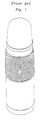
- Fig. 2 is a cross-section view illustrating an example of a portable hot water making bottle according to the present invention.
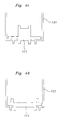
- Fig. 4 shows few examples of structures of the heat pipe applied to hot water making bottles according to the present invention.
- Fig. 5 is a cross-sectional view showing the structure of a portable hot water making bottle which is divided into a water containing means and a water heating means according to the present invention.
- Fig. 2 is a cross-sectional view showing an example of a portable hot water making bottle.
- the portable hot water making bottle can have various sizes according to the amount of water to be contained.
- the portable hot water making bottle can be a small size containing 250ml ⁇ 500ml of water, a medium size containing 500ml ⁇ 700ml of water and a large size containing 500ml ⁇ 1500ml of water. It can also have various types such as cylindrical type like the conventional vacuum insulated bottle or a kettle type.
- the body of the portable hot water making bottle includes a water containing part 100, a heating part 200 which includes a heating means and a fuel containing part 300 in which fuel provided to the heating part 200 is contained.
- the water containing part 100 has an opening portion 101 at its upper end portion, through which opening portion 101 water flows in and out.
- a cap 102 is included in the opening portion 101 in order to open and close the opening portion.
- the cap 102 is provided with an inner thread and is screwed on the upper end portion of the water containing part 100, which upper end portion is provided with a corresponding outside thread.
- the water containing part 100 is in a hollow cylindrical shape.
- a middle portion adjacent to the upper end portion of the water containing part 100 is provided with another outside thread, and a cup-shaped cover 103 provided with an inner thread is screwed onto said threaded middle portion, thereby covering the whole upper part of the water containing part 100 including the opening portion 101 and the cap 102.
- a U-shaped heat pipe 111 is installed at the water containing part 100.
- the heat pipe 111 is formed to contact the water contained in the water containing part 100 in maximum.
- One end portion of the heat pipe 111 is located in the water containing part 100 and the rest of the heat pipe is located in the heating part 200.
- the water containing part 100 comprises a bottom having a through hole through which the heat pipe extends towards the heating part 200.
- the heat pipe 111 is sealed against the inner wall of the through hole in order to prevent water from flowing from the water containing part 100 to the heating part 200.
- a heat source is installed in the heating part 200 and gas fuel such as liquid propane gas or butane gas is used as fuel for the heat source in this invention.
- An ignition portion 203 is installed at the end of a nozzle 201 and an ignition button 205 which operates the ignition portion 203 is installed at the outer surface of the body of the portable hot water making bottle.
- An ignition guide 211 forming an ignition space covers the nozzle 201 and the ignition portion 203.
- a Flame formed at the end of the nozzle 201 directly contacts the end portion of the heat pipe 111 located in the heating part 200, thereby directly heating the heat pipe 111 which itself transfers heat to the water contained in the water containing part 100 via thermal conduction.
- the ignition guide 211 and, thus, the ignition portion 203 may also be provided such that the flame only contacts the ignition guide 211 via which heat is then transferred to the heat pipe 111.
- the underside of the heat pipe 111 is formed with a recess into which the upper part of the ignition guide 211 is tightly fitted.
- the ignition guide 211 according to this embodiment is formed as hollow cylindrical body.
- the ignition guide 211 is preferably formed of metal and/or insulation material and is preferably in a mesh type. Further, the ignition guide 211 and, thus, the ignition space are insulated from a casing surrounding the heat source via an air gap so that the thermal energy from the heat source is substantially transferred to the heat pipe 111.
- the casing of heating part 200 has a cylindrical shape and is co-axially arranged with the cylindrical water containing part 100. The casing of the heating part 200 and the water containing part 100 are fixedly connected to each other at opposed axial ends.
- a fuel pipe 231 which provides fuel is connected to the nozzle 201 and the other end of the fuel pipe 231 is connected to the fuel containing part 300 which is located at the lower part of the heating part 200.
- a small fuel tank 310 is installed at the fuel containing part 300. When the small fuel tank 310 is mounted in the fuel containing part 300, one end of the fuel pipe 231 fits the outlet of the fuel tank 310. The fuel tank 310 can be changed into a new one after usage.
- the heat energy of the heating part 200 should not contact the body of the portable hot water making bottle as the heat might melt the material composing the portable hot water making bottle. Therefore, the thermal energy used in heating liquid should be exposed outwards and it is preferable to form air holes 221 around the body of the hot water making bottle. In this embodiment, there exists a sufficient gap between the ignition guide 211 and the casing of the heating part 200, so that the casing is prevented from being directly heated by the heat source, thereby avoiding loss of thermal energy.
- the heat pipe 111 is directly heated up by the flame that is made from burning the gas fuel sprayed out from the nozzle 201 at the ignition portion 203.
- direct heat from the flame may over heat the nozzle 201 and the fuel pipe 231 which may cause explosion or fire. Therefore, the embodiment according to Fig. 3 suggests a portable hot water making bottle using a low temperature thermal catalyst or thermal catalyst as a heat source without making flame.
- a low temperature thermal catalyst 213 of a meshed cylindrical sheet type is placed between the nozzle 201 and heat pipe 111.
- spark is formed at the ignition part 203 and flame is made from burning the gas sprayed out from the nozzle 201.
- the low temperature thermal catalyst 213 is heated as the flame contacts the low temperature thermal catalyst directly.
- the nozzle 201 or the fuel pipe 231 is closed to eliminate the flame and the nozzle 201 or the fuel pipe 231 is re-opened without making any spark.
- the fuel is burnt on the surface of the thermal catalyst 213 without making any flame and a bi-metal 217 can be used for controlling flame.
- One end of the flame controlling bi-metal 217 is located on the nozzle 201 at which the flame is made when the spark is generated.
- the other end of the flame controlling bi-metal 217 is located on the fuel controlling lever 209. Once the flame is generated, the flame controlling bi-metal 217 is activated at the predetermined temperature. Then the flame controlling bi-metal 217 operates the fuel controlling lever 209 to block the fuel from being supplied and the flame is eliminated.
- the fuel providing lever 209 is operated again and only the fuel is supplied to the thermal catalyst 213 again. Then, the fuel is burnt at the thermal catalyst 213 so that the thermal catalyst 213 becomes the heat source.
- the thermal catalyst should fully contact the heat pipe 111 in order to transmit the thermal energy of the heat source(or thermal catalyst 213) to the heat pipe 111 effectively.
- the embodiment 2 is similar to the embodiment 1, so that a further description of the already described parts is omitted.
- the heat pipe 111 should transmit the thermal energy from the heat source to the water effectively. Therefore, the heat pipe 111 should be designed with a certain shape in which the area of the heat pipe in contact with the water is maximized. As shown in Fig. 4a, it is preferable that the heat pipe 111 is in a U-shape like a bowl or cup and the volume of the heat pipe 111 is smaller than the volume of the water containing part 100.
- the heat pipe 111 according to Fig. 4a is provided in the embodiments according to Fig. 2 and 3.
- the heat pipe 111 according to Fig. 4a can be formed by adhering two metal plates with a gap therebetween having width of around 3mm.
- the heat pipe 111 can be made to have various shapes. It can be designed so that the inner surface of the water containing part 100 is in contact with water only as shown in Fig. 4b. In this case, the thermal energy can be transmitted to the hands of users directly so, it is preferable to cover the outer surface of the heat pipe 111 with a heat insulation material 121.
- the heat pipe 111 shown in Fig. 4c is in a cylindrical shape which is projected outwards in the center.
- the heat pipe in Fig. 4d is a in disk shape like a thin plate in which the edge part is projected.
- the heat pipe 111 of these two shapes can be used in situations like preparing milk for babies where water needs to be heated up to only about 30 to 40 centigrade.
- the heat pipe 111 in Fig. 4e is in a screw or coil shape, here, the heat pipe 111 is thin enough to be bent and is formed on the plane surface.
- the inside of the heat pipe is in a vacuumed state which has low air pressure than the outside and is filled with a liquid type material for transmitting heat.
- a liquid type material for transmitting heat.
- the liquid material inside the pipe is heated and vaporizes. Eventually, the heat is transmitted to the other end of the pipe.
Landscapes
- Engineering & Computer Science (AREA)
- Physics & Mathematics (AREA)
- Thermal Sciences (AREA)
- Food Science & Technology (AREA)
- Chemical & Material Sciences (AREA)
- Combustion & Propulsion (AREA)
- Mechanical Engineering (AREA)
- General Engineering & Computer Science (AREA)
- Cookers (AREA)
- Thermally Insulated Containers For Foods (AREA)
- Thermotherapy And Cooling Therapy Devices (AREA)
Applications Claiming Priority (2)
| Application Number | Priority Date | Filing Date | Title |
|---|---|---|---|
| KR2000010147 | 2000-02-29 | ||
| KR10-2000-0010147A KR100370373B1 (ko) | 2000-02-29 | 2000-02-29 | 휴대용 순간 온수기 |
Publications (2)
| Publication Number | Publication Date |
|---|---|
| EP1129655A1 true EP1129655A1 (de) | 2001-09-05 |
| EP1129655B1 EP1129655B1 (de) | 2004-05-12 |
Family
ID=19651167
Family Applications (1)
| Application Number | Title | Priority Date | Filing Date |
|---|---|---|---|
| EP01104823A Expired - Lifetime EP1129655B1 (de) | 2000-02-29 | 2001-02-27 | Eine tragbare Heisswassererhitzungsflasche |
Country Status (9)
| Country | Link |
|---|---|
| US (1) | US6431124B2 (de) |
| EP (1) | EP1129655B1 (de) |
| JP (1) | JP2001269269A (de) |
| KR (1) | KR100370373B1 (de) |
| CN (1) | CN1148143C (de) |
| AT (1) | ATE266347T1 (de) |
| AU (1) | AU1000301A (de) |
| CA (1) | CA2327537A1 (de) |
| DE (1) | DE60103196T2 (de) |
Cited By (1)
| Publication number | Priority date | Publication date | Assignee | Title |
|---|---|---|---|---|
| FR2867264A1 (fr) | 2004-03-04 | 2005-09-09 | Claude Godet | Dispositif autonome de chauffage d'un liquide et procede de chauffage d'un liquide |
Families Citing this family (15)
| Publication number | Priority date | Publication date | Assignee | Title |
|---|---|---|---|---|
| SE0201926D0 (sv) * | 2002-06-18 | 2002-06-18 | Lennart Rantzen | Anordning vid ett hetluftsaggregat |
| AU2003245665A1 (en) * | 2002-06-25 | 2004-01-06 | Jetboil, Inc. | Heating vessel |
| US8474648B1 (en) * | 2005-01-03 | 2013-07-02 | Bic Corporation | Thermos and cup combination |
| WO2009003481A2 (en) * | 2007-07-03 | 2009-01-08 | Heatgear Professional Aps | Catalytic heater |
| US8558145B2 (en) | 2008-01-16 | 2013-10-15 | Chien-Cheng Lin | Heat retaining bottle |
| US8844513B2 (en) * | 2008-07-07 | 2014-09-30 | John Stock LaMunyon, III | Apparatus, system and method for heating a ventilation system |
| US9648970B2 (en) | 2012-09-13 | 2017-05-16 | Simon Sung Lee | Impact-resistant portable liquid container protector with cooling and heating capability |
| CA2889221A1 (en) * | 2012-11-06 | 2014-05-15 | Heatgenie, Inc. | Heating devices and methods with auto-shutdown |
| CN104083051A (zh) * | 2014-06-30 | 2014-10-08 | 南京信息工程大学 | 摩擦加热保温杯 |
| CN104083286A (zh) * | 2014-08-04 | 2014-10-08 | 刘影 | 一种便携式奶瓶加热座 |
| WO2017219129A1 (en) | 2016-06-21 | 2017-12-28 | John Robert Mumford | Beverage containers, heat transfer pad, and related system and methods |
| CN105942878A (zh) * | 2016-07-16 | 2016-09-21 | 史宪文 | 一种快速饮料加热器 |
| DE102016012323A1 (de) * | 2016-10-17 | 2018-04-19 | Frank Pelzer | Tragbare Handvorrichtung zum Aufnehmen und Transportieren einer Speise oder eines Getränks und Verfahren zum Temperieren |
| CN109077612A (zh) * | 2017-06-13 | 2018-12-25 | 乐山加兴科技有限公司 | 带有雾化器的智能电加热式开水瓶 |
| KR20250032486A (ko) * | 2023-08-31 | 2025-03-07 | 이장근 | 휴대용 가스버너 |
Citations (6)
| Publication number | Priority date | Publication date | Assignee | Title |
|---|---|---|---|---|
| DE338680C (de) * | 1919-01-30 | 1921-06-29 | Nuernberger Metall Und Lackier | Isoliergefaess mit Vakuummantel und elektrischer Beheizung |
| US3804076A (en) * | 1973-03-30 | 1974-04-16 | J Fant | Baby bottle warmer |
| US4675508A (en) * | 1984-06-29 | 1987-06-23 | Nippon Sanso Kabushiki Kaisha | Electrically heated vacuum bottle |
| EP0790027A1 (de) * | 1996-02-15 | 1997-08-20 | Nissho Corporation | Wärmeisolierter elektrischer Kochtopf |
| JPH10179390A (ja) * | 1996-12-26 | 1998-07-07 | Matsushita Electric Ind Co Ltd | 加熱機能付き保温ポット |
| JPH10179391A (ja) * | 1996-12-26 | 1998-07-07 | Matsushita Electric Ind Co Ltd | 加熱機能付き保温ポット |
Family Cites Families (8)
| Publication number | Priority date | Publication date | Assignee | Title |
|---|---|---|---|---|
| US3709198A (en) * | 1971-07-22 | 1973-01-09 | G Williams | Liquid heater and storage means |
| US4495404A (en) * | 1982-09-27 | 1985-01-22 | Carmichael Wayne E | Self-contained compact electric beverage brewing travel kit |
| AU3574193A (en) * | 1992-02-12 | 1993-09-03 | Tokai Corporation | Portable heater |
| DE29501228U1 (de) * | 1995-01-26 | 1995-05-04 | Timm Eberhard | Vorrichtung zum Erhitzen einer trinkbaren Flüssigkeit |
| JP3533855B2 (ja) * | 1996-12-26 | 2004-05-31 | 松下電器産業株式会社 | 加熱機能付き保温ポット |
| JPH10314025A (ja) * | 1997-05-16 | 1998-12-02 | Matsushita Electric Ind Co Ltd | 触媒燃焼装置およびこれを有する保温ポットおよびこれを有する加熱調理器 |
| KR200164865Y1 (ko) * | 1998-02-26 | 2000-01-15 | 유재원 | 가스버너의 가스 차단장치 |
| US6086216A (en) * | 1998-12-22 | 2000-07-11 | Goldfarb; Eric A. | Bottle lantern |
-
2000
- 2000-02-29 KR KR10-2000-0010147A patent/KR100370373B1/ko not_active Expired - Fee Related
- 2000-12-05 CA CA002327537A patent/CA2327537A1/en not_active Abandoned
- 2000-12-13 CN CNB001282344A patent/CN1148143C/zh not_active Expired - Fee Related
-
2001
- 2001-01-04 AU AU10003/01A patent/AU1000301A/en not_active Abandoned
- 2001-02-26 JP JP2001050347A patent/JP2001269269A/ja active Pending
- 2001-02-27 AT AT01104823T patent/ATE266347T1/de not_active IP Right Cessation
- 2001-02-27 EP EP01104823A patent/EP1129655B1/de not_active Expired - Lifetime
- 2001-02-27 DE DE60103196T patent/DE60103196T2/de not_active Expired - Fee Related
- 2001-02-28 US US09/794,141 patent/US6431124B2/en not_active Expired - Fee Related
Patent Citations (6)
| Publication number | Priority date | Publication date | Assignee | Title |
|---|---|---|---|---|
| DE338680C (de) * | 1919-01-30 | 1921-06-29 | Nuernberger Metall Und Lackier | Isoliergefaess mit Vakuummantel und elektrischer Beheizung |
| US3804076A (en) * | 1973-03-30 | 1974-04-16 | J Fant | Baby bottle warmer |
| US4675508A (en) * | 1984-06-29 | 1987-06-23 | Nippon Sanso Kabushiki Kaisha | Electrically heated vacuum bottle |
| EP0790027A1 (de) * | 1996-02-15 | 1997-08-20 | Nissho Corporation | Wärmeisolierter elektrischer Kochtopf |
| JPH10179390A (ja) * | 1996-12-26 | 1998-07-07 | Matsushita Electric Ind Co Ltd | 加熱機能付き保温ポット |
| JPH10179391A (ja) * | 1996-12-26 | 1998-07-07 | Matsushita Electric Ind Co Ltd | 加熱機能付き保温ポット |
Non-Patent Citations (1)
| Title |
|---|
| PATENT ABSTRACTS OF JAPAN vol. 1998, no. 12 31 October 1998 (1998-10-31) * |
Cited By (2)
| Publication number | Priority date | Publication date | Assignee | Title |
|---|---|---|---|---|
| FR2867264A1 (fr) | 2004-03-04 | 2005-09-09 | Claude Godet | Dispositif autonome de chauffage d'un liquide et procede de chauffage d'un liquide |
| EP1570775A3 (de) * | 2004-03-04 | 2006-04-26 | Claude Godet | Autonome Wärmevorrichtung für Flüssigkeit und Verfahren zum Erwärmen einer Flüssigkeit |
Also Published As
| Publication number | Publication date |
|---|---|
| KR100370373B1 (ko) | 2003-01-29 |
| DE60103196D1 (de) | 2004-06-17 |
| US6431124B2 (en) | 2002-08-13 |
| US20010023693A1 (en) | 2001-09-27 |
| CN1148143C (zh) | 2004-05-05 |
| AU1000301A (en) | 2001-08-30 |
| KR20000071923A (ko) | 2000-12-05 |
| CN1310977A (zh) | 2001-09-05 |
| DE60103196T2 (de) | 2005-05-19 |
| EP1129655B1 (de) | 2004-05-12 |
| JP2001269269A (ja) | 2001-10-02 |
| CA2327537A1 (en) | 2001-08-29 |
| ATE266347T1 (de) | 2004-05-15 |
Similar Documents
| Publication | Publication Date | Title |
|---|---|---|
| EP1129655B1 (de) | Eine tragbare Heisswassererhitzungsflasche | |
| US5690094A (en) | Gas flame kettle | |
| US20100175637A1 (en) | Catalytic heater | |
| US4793321A (en) | Self-priming alcohol stove | |
| US4829981A (en) | Portable warming apparatus for a cup | |
| WO1983000425A1 (en) | Heating device | |
| US20140197180A1 (en) | Heated mug | |
| JP2868066B2 (ja) | 即熱式貯湯型電気温水器 | |
| AU687898B2 (en) | Gas-flame kettle | |
| JP3130671B2 (ja) | 容器の保持装置 | |
| HK1039042A (en) | An instant portable hot making bottle | |
| US20090090353A1 (en) | Apparatus and Method for a Self-Contained Heating Vessel | |
| US20070107715A1 (en) | Apparatus and Method for a Self-Contained Heating Vessel | |
| KR200240774Y1 (ko) | 화로형 맥반석 난로 | |
| KR20010000510U (ko) | 휴대용 가스버너의 가스통 온도조절장치와 열감지 안전장치 | |
| JPH05269044A (ja) | 加熱器具における外筒体の構造 | |
| JP2001004109A (ja) | 触媒燃焼器 | |
| KR200218985Y1 (ko) | 온수관이 구비된 가스화덕 | |
| KR200263678Y1 (ko) | 휴대용 가스버너의 안전장치 | |
| KR102071030B1 (ko) | 휴대용 가스레인지 및 그에 이용되는 열전달수단 | |
| KR20040006076A (ko) | 히터용 포트장치 | |
| JPH0614692Y2 (ja) | 湯沸かし容器 | |
| JPS58412Y2 (ja) | 保温式ガス炊飯器の排気構造 | |
| JP2563399Y2 (ja) | 保温式ガス炊飯器 | |
| JPS5935611B2 (ja) | ガス炊飯電気保温ジヤ− |
Legal Events
| Date | Code | Title | Description |
|---|---|---|---|
| PUAI | Public reference made under article 153(3) epc to a published international application that has entered the european phase |
Free format text: ORIGINAL CODE: 0009012 |
|
| AK | Designated contracting states |
Kind code of ref document: A1 Designated state(s): AT BE CH CY DE DK ES FI FR GB GR IE IT LI LU MC NL PT SE TR |
|
| AX | Request for extension of the european patent |
Free format text: AL;LT;LV;MK;RO;SI |
|
| RIN1 | Information on inventor provided before grant (corrected) |
Inventor name: KWON, YUN SANG |
|
| 17P | Request for examination filed |
Effective date: 20020305 |
|
| AKX | Designation fees paid |
Free format text: AT BE CH CY DE DK ES FI FR GB GR IE IT LI LU MC NL PT SE TR |
|
| 17Q | First examination report despatched |
Effective date: 20020701 |
|
| GRAP | Despatch of communication of intention to grant a patent |
Free format text: ORIGINAL CODE: EPIDOSNIGR1 |
|
| GRAS | Grant fee paid |
Free format text: ORIGINAL CODE: EPIDOSNIGR3 |
|
| GRAA | (expected) grant |
Free format text: ORIGINAL CODE: 0009210 |
|
| AK | Designated contracting states |
Kind code of ref document: B1 Designated state(s): AT BE CH CY DE DK ES FI FR GB GR IE IT LI LU MC NL PT SE TR |
|
| PG25 | Lapsed in a contracting state [announced via postgrant information from national office to epo] |
Ref country code: IT Free format text: LAPSE BECAUSE OF FAILURE TO SUBMIT A TRANSLATION OF THE DESCRIPTION OR TO PAY THE FEE WITHIN THE PRESCRIBED TIME-LIMIT;WARNING: LAPSES OF ITALIAN PATENTS WITH EFFECTIVE DATE BEFORE 2007 MAY HAVE OCCURRED AT ANY TIME BEFORE 2007. THE CORRECT EFFECTIVE DATE MAY BE DIFFERENT FROM THE ONE RECORDED. Effective date: 20040512 Ref country code: LI Free format text: LAPSE BECAUSE OF FAILURE TO SUBMIT A TRANSLATION OF THE DESCRIPTION OR TO PAY THE FEE WITHIN THE PRESCRIBED TIME-LIMIT Effective date: 20040512 Ref country code: NL Free format text: LAPSE BECAUSE OF FAILURE TO SUBMIT A TRANSLATION OF THE DESCRIPTION OR TO PAY THE FEE WITHIN THE PRESCRIBED TIME-LIMIT Effective date: 20040512 Ref country code: AT Free format text: LAPSE BECAUSE OF FAILURE TO SUBMIT A TRANSLATION OF THE DESCRIPTION OR TO PAY THE FEE WITHIN THE PRESCRIBED TIME-LIMIT Effective date: 20040512 Ref country code: FI Free format text: LAPSE BECAUSE OF FAILURE TO SUBMIT A TRANSLATION OF THE DESCRIPTION OR TO PAY THE FEE WITHIN THE PRESCRIBED TIME-LIMIT Effective date: 20040512 Ref country code: BE Free format text: LAPSE BECAUSE OF FAILURE TO SUBMIT A TRANSLATION OF THE DESCRIPTION OR TO PAY THE FEE WITHIN THE PRESCRIBED TIME-LIMIT Effective date: 20040512 Ref country code: CH Free format text: LAPSE BECAUSE OF FAILURE TO SUBMIT A TRANSLATION OF THE DESCRIPTION OR TO PAY THE FEE WITHIN THE PRESCRIBED TIME-LIMIT Effective date: 20040512 Ref country code: TR Free format text: LAPSE BECAUSE OF FAILURE TO SUBMIT A TRANSLATION OF THE DESCRIPTION OR TO PAY THE FEE WITHIN THE PRESCRIBED TIME-LIMIT Effective date: 20040512 |
|
| REG | Reference to a national code |
Ref country code: GB Ref legal event code: FG4D |
|
| REG | Reference to a national code |
Ref country code: CH Ref legal event code: EP |
|
| REG | Reference to a national code |
Ref country code: IE Ref legal event code: FG4D |
|
| REF | Corresponds to: |
Ref document number: 60103196 Country of ref document: DE Date of ref document: 20040617 Kind code of ref document: P |
|
| PG25 | Lapsed in a contracting state [announced via postgrant information from national office to epo] |
Ref country code: GR Free format text: LAPSE BECAUSE OF FAILURE TO SUBMIT A TRANSLATION OF THE DESCRIPTION OR TO PAY THE FEE WITHIN THE PRESCRIBED TIME-LIMIT Effective date: 20040812 Ref country code: DK Free format text: LAPSE BECAUSE OF FAILURE TO SUBMIT A TRANSLATION OF THE DESCRIPTION OR TO PAY THE FEE WITHIN THE PRESCRIBED TIME-LIMIT Effective date: 20040812 Ref country code: SE Free format text: LAPSE BECAUSE OF FAILURE TO SUBMIT A TRANSLATION OF THE DESCRIPTION OR TO PAY THE FEE WITHIN THE PRESCRIBED TIME-LIMIT Effective date: 20040812 |
|
| PG25 | Lapsed in a contracting state [announced via postgrant information from national office to epo] |
Ref country code: ES Free format text: LAPSE BECAUSE OF FAILURE TO SUBMIT A TRANSLATION OF THE DESCRIPTION OR TO PAY THE FEE WITHIN THE PRESCRIBED TIME-LIMIT Effective date: 20040823 |
|
| NLV1 | Nl: lapsed or annulled due to failure to fulfill the requirements of art. 29p and 29m of the patents act | ||
| REG | Reference to a national code |
Ref country code: CH Ref legal event code: PL |
|
| PG25 | Lapsed in a contracting state [announced via postgrant information from national office to epo] |
Ref country code: CY Free format text: LAPSE BECAUSE OF FAILURE TO SUBMIT A TRANSLATION OF THE DESCRIPTION OR TO PAY THE FEE WITHIN THE PRESCRIBED TIME-LIMIT Effective date: 20050227 Ref country code: LU Free format text: LAPSE BECAUSE OF NON-PAYMENT OF DUE FEES Effective date: 20050227 |
|
| PG25 | Lapsed in a contracting state [announced via postgrant information from national office to epo] |
Ref country code: MC Free format text: LAPSE BECAUSE OF NON-PAYMENT OF DUE FEES Effective date: 20050228 Ref country code: IE Free format text: LAPSE BECAUSE OF NON-PAYMENT OF DUE FEES Effective date: 20050228 |
|
| PGFP | Annual fee paid to national office [announced via postgrant information from national office to epo] |
Ref country code: DE Payment date: 20050228 Year of fee payment: 5 |
|
| PLBE | No opposition filed within time limit |
Free format text: ORIGINAL CODE: 0009261 |
|
| STAA | Information on the status of an ep patent application or granted ep patent |
Free format text: STATUS: NO OPPOSITION FILED WITHIN TIME LIMIT |
|
| 26N | No opposition filed |
Effective date: 20050215 |
|
| EN | Fr: translation not filed | ||
| REG | Reference to a national code |
Ref country code: FR Ref legal event code: FC Ref country code: FR Ref legal event code: RN |
|
| PGFP | Annual fee paid to national office [announced via postgrant information from national office to epo] |
Ref country code: GB Payment date: 20050713 Year of fee payment: 5 |
|
| ET | Fr: translation filed | ||
| REG | Reference to a national code |
Ref country code: IE Ref legal event code: MM4A |
|
| PG25 | Lapsed in a contracting state [announced via postgrant information from national office to epo] |
Ref country code: GB Free format text: LAPSE BECAUSE OF NON-PAYMENT OF DUE FEES Effective date: 20060227 |
|
| PG25 | Lapsed in a contracting state [announced via postgrant information from national office to epo] |
Ref country code: DE Free format text: LAPSE BECAUSE OF NON-PAYMENT OF DUE FEES Effective date: 20060901 |
|
| GBPC | Gb: european patent ceased through non-payment of renewal fee |
Effective date: 20060227 |
|
| PG25 | Lapsed in a contracting state [announced via postgrant information from national office to epo] |
Ref country code: PT Free format text: LAPSE BECAUSE OF NON-PAYMENT OF DUE FEES Effective date: 20041012 |
|
| PG25 | Lapsed in a contracting state [announced via postgrant information from national office to epo] |
Ref country code: FR Free format text: LAPSE BECAUSE OF NON-PAYMENT OF DUE FEES Effective date: 20050228 |
|
| REG | Reference to a national code |
Ref country code: FR Ref legal event code: ST Effective date: 20111209 |