EP1129682A2 - Device for liquid balancing for enteral nutrition of patients - Google Patents
Device for liquid balancing for enteral nutrition of patients Download PDFInfo
- Publication number
- EP1129682A2 EP1129682A2 EP01104773A EP01104773A EP1129682A2 EP 1129682 A2 EP1129682 A2 EP 1129682A2 EP 01104773 A EP01104773 A EP 01104773A EP 01104773 A EP01104773 A EP 01104773A EP 1129682 A2 EP1129682 A2 EP 1129682A2
- Authority
- EP
- European Patent Office
- Prior art keywords
- shut
- container
- distributor device
- connecting line
- distributor
- Prior art date
- Legal status (The legal status is an assumption and is not a legal conclusion. Google has not performed a legal analysis and makes no representation as to the accuracy of the status listed.)
- Withdrawn
Links
Images


Classifications
-
- A—HUMAN NECESSITIES
- A61—MEDICAL OR VETERINARY SCIENCE; HYGIENE
- A61J—CONTAINERS SPECIALLY ADAPTED FOR MEDICAL OR PHARMACEUTICAL PURPOSES; DEVICES OR METHODS SPECIALLY ADAPTED FOR BRINGING PHARMACEUTICAL PRODUCTS INTO PARTICULAR PHYSICAL OR ADMINISTERING FORMS; DEVICES FOR ADMINISTERING FOOD OR MEDICINES ORALLY; BABY COMFORTERS; DEVICES FOR RECEIVING SPITTLE
- A61J15/00—Feeding-tubes for therapeutic purposes
- A61J15/0026—Parts, details or accessories for feeding-tubes
-
- A—HUMAN NECESSITIES
- A61—MEDICAL OR VETERINARY SCIENCE; HYGIENE
- A61M—DEVICES FOR INTRODUCING MEDIA INTO, OR ONTO, THE BODY; DEVICES FOR TRANSDUCING BODY MEDIA OR FOR TAKING MEDIA FROM THE BODY; DEVICES FOR PRODUCING OR ENDING SLEEP OR STUPOR
- A61M39/00—Tubes, tube connectors, tube couplings, valves, access sites or the like, specially adapted for medical use
- A61M39/22—Valves or arrangement of valves
- A61M39/223—Multiway valves
-
- A—HUMAN NECESSITIES
- A61—MEDICAL OR VETERINARY SCIENCE; HYGIENE
- A61M—DEVICES FOR INTRODUCING MEDIA INTO, OR ONTO, THE BODY; DEVICES FOR TRANSDUCING BODY MEDIA OR FOR TAKING MEDIA FROM THE BODY; DEVICES FOR PRODUCING OR ENDING SLEEP OR STUPOR
- A61M5/00—Devices for bringing media into the body in a subcutaneous, intra-vascular or intramuscular way; Accessories therefor, e.g. filling or cleaning devices, arm rests
- A61M5/14—Infusion devices, e.g. infusing by gravity; Blood infusion; Accessories therefor
- A61M5/1407—Infusion of two or more substances
- A61M5/1408—Infusion of two or more substances in parallel, e.g. by manifolds or with sequencing valves
-
- A—HUMAN NECESSITIES
- A61—MEDICAL OR VETERINARY SCIENCE; HYGIENE
- A61J—CONTAINERS SPECIALLY ADAPTED FOR MEDICAL OR PHARMACEUTICAL PURPOSES; DEVICES OR METHODS SPECIALLY ADAPTED FOR BRINGING PHARMACEUTICAL PRODUCTS INTO PARTICULAR PHYSICAL OR ADMINISTERING FORMS; DEVICES FOR ADMINISTERING FOOD OR MEDICINES ORALLY; BABY COMFORTERS; DEVICES FOR RECEIVING SPITTLE
- A61J15/00—Feeding-tubes for therapeutic purposes
-
- A—HUMAN NECESSITIES
- A61—MEDICAL OR VETERINARY SCIENCE; HYGIENE
- A61M—DEVICES FOR INTRODUCING MEDIA INTO, OR ONTO, THE BODY; DEVICES FOR TRANSDUCING BODY MEDIA OR FOR TAKING MEDIA FROM THE BODY; DEVICES FOR PRODUCING OR ENDING SLEEP OR STUPOR
- A61M39/00—Tubes, tube connectors, tube couplings, valves, access sites or the like, specially adapted for medical use
- A61M39/22—Valves or arrangement of valves
- A61M39/229—Single-way cut-off valves
Definitions
- the invention relates to a device for Fluid balance in enterally fed patients with a first container and a second container, each with a connecting line leading to the patient via a Connect the connector, taking the container different content, like food and liquid, different liquids or foods or the like included.
- the invention is based on the object Device with the above-mentioned features train that simple and quick handling is possible.
- connection piece as a shut-off distributor device with several Functional positions is formed with which Flow connection between the first and / or second Container and the connecting line optionally manufactured and is interrupted
- the shut-off distributor device has three functional positions on, with only the first in a first functional position Containers in flow communication and in a second Function position only the second container in Flow connection with the connecting line and in a third functional position the flow connection of first and second container to the connecting line interrupted is. Because of this measure, the contents of the container by setting the Shut-off distributor device to the patient via the Connection line can be supplied alternatively, but also it is possible to supply the contents of the container to prevent from both containers.
- the shut-off distributor device is according to another advantageous embodiment of the invention essentially according kind of a three-way cock trained and the chick by means a hand bolt or similar actuating means in the respective functional position can be transferred. It is an advantage Chick rotatable in the housing of the shutoff manifold stored and it has the actuating means, if it is manually operated, a hand bolt in the form of a T-piece or Y-piece.
- the Actuating means for example the hand latch or the like, one on the shutoff manifold arranged stop is assigned to the pivot angle of the hand bolt to an angle of preferably approximately 180 ° or also limited somewhat below.
- the hand latch as a T-piece formed, so the end pieces of the substantially the axis of rotation of the chick arranged free ends of the Strike the T-cross leg against the stop and thus the Limit swivel angle to approx. 180 ° or a little less.
- the T-longitudinal leg is designed such that this is pivotable over the stop, whereby in particular an intermediate position of the hand latch for the User can be made visible or made clear.
- the first or third functional position of the shut-off distributor device that in one of the two angular end positions of the swivel angle positioned actuating means is determined.
- the second functional position is advantageous Shut-off device in one between the two Angular end positions, preferably in a middle angular position positioned, preferably in this functional position lockable actuating means determined.
- This middle one Angular position can be assumed, for example, when the T-longitudinal leg is above the stop.
- Another embodiment is particularly advantageous the invention the first container of food and the second Container filled with liquid. Because of this measure made sure that the Flow connection from the first and second container to Connection line first from the supply of food to the Liquid supply must be switched over until then the locking position is reached. This is ensures that when the supply of Food before completely blocking the flow connection first switch to the supply of liquid must, causing forced flushing of the shut-off distributor device with liquid before switching off completely is achieved.
- the shut-off distributor device is in the locked position for first connector on which the liquid container connected, open.
- the locked position is in the third functional position in which the Flow connection from the first and second container to Connection line is interrupted.
- the Shut-off distributor device closed.
- the first Container via an insert part of the Shut-off distributor device, the second container via a Supply line and a first connection piece and the Connection line via a second connecting piece, preferred with pressure bush and seal, with the Shut-off distributor device connected.
- the second An external thread can be used, for example, for connecting pieces have, so that the connecting line, for example by means of a union nut securely on the shut-off distributor device is to be attached.
- the plug-in part and the second connecting piece essentially are arranged coaxially adjacent to each other and the first Connecting piece with the second connecting piece at an angle, for example of about 60 °.
- the channels of the Insert part and the two connecting pieces meet in a central area of the housing Shut-off distributor device in which the chick is pivoted is recorded.
- the positioning of Insert part and connecting pieces of the Storage distributor device in a top view of a Y-shape.
- the contents of the container contacting walls of the Shut-off distributor device in particular its Channel inner walls in the area of the plug-in part, the first and second connecting piece and the chick respectively the pot-shaped receptacle for the chick does not have dead spaces.
- care is taken to ensure that when inserting or connecting the supply lines or connecting lines or the container there are no dead spaces in which bacteria or could form the like.
- the Device preferably an integral part of the Transfer system, for example the connecting line. So can provide the end of the device with an external thread and be shaped as a tube seat.
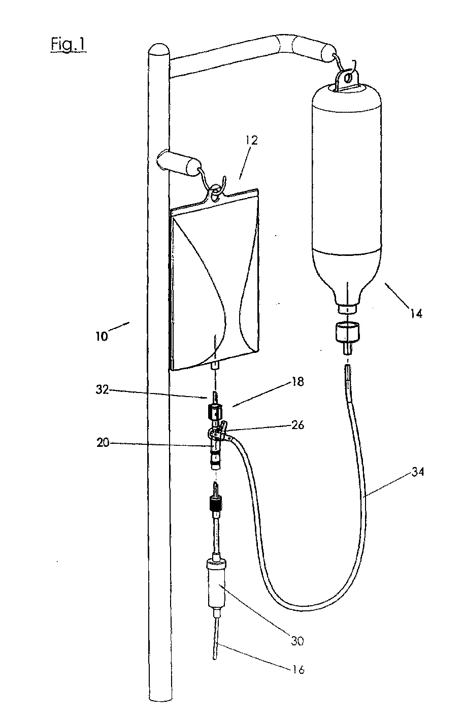
- the device 10 shown in Figure 1 for Fluid balancing in enterally nourished patients a first container 12 and a second container 14. These containers 12, 14 are each one with the patient leading connecting line 16 via a connector 18th connected.
- the containers 12, 14 are different Content, such as different foods, different liquids or food or liquid or the like filled.
- the Connector 18 is as a shut-off manifold 20 trained several functional positions. About these Shut-off manifold 20 can flow connection between the first and / or second container 12, 14 and the Connection line 16 optionally manufactured or to be interrupted.
- the shutoff distributor device 20 has three Functional positions, being in a first Functional position, which is clear, for example, from FIGS. 2, 4 5 and 5, only the first container 12 in Flow connection with the connecting line 16 is.
- a second functional position in which the actuating means 26 the barrier manifold 20 counterclockwise only 90 ° or a little less, only the second one stands Container 14 in flow connection with connecting line 16.
- a third functional position is provided at the actuating means 26 with respect to the first Functional position by approx. 180 ° or a little less against the Is adjusted clockwise. In this position Flow connection from the first and second containers 12, 14 to Connection line 16 or the second connecting piece 38 interrupted. How the Shut-off manifold 20 is particularly by the Sectional illustration of Figure 4 illustrates.
- the shutoff manifold 20 is substantially after Type of a three-way valve 22 is formed, the plug 24 of the Hahns by means of a latch or the like Actuating means 26 in the respective functional position transferable. Furthermore, the actuating means 26 for Example the hand latch or the like, one on the Shut-off distributor device 20 arranged stop 28 assigned, as can be seen particularly clearly from FIG. 5 can be seen.
- the stop 28 limits the pivoting angle of the actuating means 26 to an angular range of preferably about 180 ° or slightly less.
- the first and third functional position of the shut-off distributor device 20 by the in one of the two angular end positions Determined pivoting actuating means 26.
- the second functional position of the shut-off distributor device 20 is by the in one between the two angular end positions, preferably positioned in a middle angular position, and in this position lockable actuating means 26 defined.
- first container 12 with food and the second Container 14 is filled with liquid so that in front of one completely blocking the flow connection between the two Containers 12 and 14 and the connecting line 16 in any case a flow connection between the second, with liquid filled container 14 and the connecting line 16 created is, so that a forced rinsing with liquid before complete shutdown of the device takes place.
- the third functional position is Shut-off distributor device 20 shown, which for the first Connection piece 36 on which the second filled with liquid Container 14 is connected, is open. Second Connection piece 38 out, on which the leading to the patient Connection line 16 is attached, and the insertion part 32nd which is filled with the first container 12 is connected, the shut-off manifold 20 is against it closed.
- the shut-off distributor device 20 is thus in their locked position always filled with liquid, so that a Loosening or caking of solid foods Substances that are not removed by forced rinsing could, is prevented.
- the device 10 has a only metering device 30, such as an overflow system or a pump or the like, with the metering device 30 in the from the shutoff manifold 20 to the patient leading connecting line 16 is arranged.
- a only metering device 30, such as an overflow system or a pump or the like with the metering device 30 in the from the shutoff manifold 20 to the patient leading connecting line 16 is arranged.
- the shut-off distributor device 20 or its Actuating means 26 can be manual, electromotive or else electronically controlled in the different Functional positions are transferred.
- the first container 12 is via an insert 32 Shut-off manifold 20 connected to this while the second container 14 via a supply line 34 and one first connection piece 36 with the shut-off distributor device 20 communicates.
- the connecting line 16, however, is via a second connecting piece 38, preferably with Pressure sleeve 40 and seal 42 to which Shut-off distributor device 20 connected.
- the insert part 32 and the second connecting piece 38 are essentially arranged coaxially adjacent to each other, the first Connection piece 36 with the second connection piece 38 a Includes angle 44 of approximately 60 °.
Landscapes
- Health & Medical Sciences (AREA)
- Life Sciences & Earth Sciences (AREA)
- Veterinary Medicine (AREA)
- Public Health (AREA)
- General Health & Medical Sciences (AREA)
- Heart & Thoracic Surgery (AREA)
- Animal Behavior & Ethology (AREA)
- Anesthesiology (AREA)
- Hematology (AREA)
- Biomedical Technology (AREA)
- Engineering & Computer Science (AREA)
- Vascular Medicine (AREA)
- Pulmonology (AREA)
- Infusion, Injection, And Reservoir Apparatuses (AREA)
- Medical Preparation Storing Or Oral Administration Devices (AREA)
Abstract
Es wird eine Vorrichtung (10) zur Flüssigkeitsbilanzierung bei
enteral ernährten Patienten mit einem ersten Behälter (12) und
einem zweiten Behälter (14) beschrieben, die jeweils mit einer
zum Patienten führenden Anschlußleitung (16) über ein
Anschlußstück (18) in Verbindung stehen, wobei die Behälter
(12, 14) unterschiedliche Inhalte aufweisen können. Das
Anschlußstück (18) ist als Absperrverteilervorrichtung (20)
mit mehreren Funktionsstellungen ausgebildet, wobei mit der
Absperrverteilervorrichtung (20) die Strömungsverbindung
zwischen dem ersten und/oder zweiten Behälter (12, 14) und der
Anschlußleitung (16) wahlweise hergestellt und unterbrochen
wird (Figur 1).
Description
Die Erfindung betrifft eine Vorrichtung zur Flüssigkeitsbilanzierung bei enteral ernährten Patienten mit einem ersten Behälter und einem zweiten Behälter, die jeweils mit einer zum Patienten führenden Anschlußleitung über ein Anschlußstück in Verbindung stehen, wobei die Behälter unterschiedliche Inhalte, wie Nahrung und Flüssigkeit, unterschiedliche Flüssigkeiten beziehungsweise Nahrungen oder dergleichen enthalten.The invention relates to a device for Fluid balance in enterally fed patients with a first container and a second container, each with a connecting line leading to the patient via a Connect the connector, taking the container different content, like food and liquid, different liquids or foods or the like included.
Die bislang eingesetzten Vorrichtungen zur Flüssigkeitsbilanzierung bei enteral ernährten Patienten weisen den Nachteil einer komplizierten Handhabung auf. Die beiden Behälter werden jeweils über separate Zufuhrleitungen mit einem Anschlußstück verbunden, wobei dann vom Anschlußstück eine Anschlußleitung hin zum Patienten geführt ist. In jeder der Zufuhrleitungen zum Anschlußstück ist eine Dosiervorrichtung vorgesehen, so daß zum einen jede der Dosiervorrichtungen separat eingestellt werden muß. Zum anderen ist es bei den bekannten Vorrichtungen erforderlich, bei dem Anschluß eines Behälters die jeweilige Zufuhrleitung zu diskonektieren. Insgesamt lassen sich die bekannten Vorrichtungen nur umständlich und aufwendig bedienen.The devices used to date Fluid balance in enterally fed patients have the disadvantage of complicated handling. The both tanks are each via separate feed lines connected to a connector, then from Connection piece led a connecting line to the patient is. There is one in each of the supply lines to the connector Dosing device provided so that on the one hand each of the Dosing devices must be set separately. To the others it is necessary in the known devices the respective supply line when a container is connected to disconect. Overall, the well-known Operate devices only cumbersome and complex.
Demgegenüber liegt der Erfindung die Aufgabe zugrunde, eine Vorrichtung mit den eingangs genannten Merkmalen dahingehend weiterzubilden, daß eine einfache und rasche Handhabung ermöglicht ist.In contrast, the invention is based on the object Device with the above-mentioned features train that simple and quick handling is possible.
Diese Aufgabe wird bei der Vorrichtung mit den eingangs genannten Merkmalen im wesentlichen dadurch gelöst, daß das Anschlußstück als Absperrverteilervorrichtung mit mehreren Funktionsstellungen ausgebildet ist, mit der die Strömungsverbindung zwischen dem ersten und/oder zweiten Behälter und der Anschlußleitung wahlweise hergestellt und unterbrochen wirdThis task is the device with the above mentioned features essentially solved in that the Connection piece as a shut-off distributor device with several Functional positions is formed with which Flow connection between the first and / or second Container and the connecting line optionally manufactured and is interrupted
Aufgrund dieser Maßnahme ist es nicht mehr erforderlich, die Zufuhrleitung zu dem jeweiligen Behälter zu diskonektieren, um diesen Behälter anzuschließen. Weiterhin kann aufgrund dieser Maßnahme die Vorrichtung unter Einsatz einer einzigen Dosiervorrichtung betrieben werden, wodurch der Handhabungsbeziehungsweise Einstellungsaufwand weiter reduziert wird.Because of this measure, it is no longer necessary to Disconnect supply line to the respective container in order to to connect this container. Furthermore, due to this Measure the device using a single one Dosing device are operated, which makes the handling or Hiring effort is further reduced.
Nach einer ersten vorteilhaften Weiterbildung der Erfindung weist die Absperrverteilervorrichtung drei Funktionsstellungen auf, wobei in einer ersten Funktionsstellung nur der erste Behälter in Strömungsverbindung und in einer zweiten Funktionsstellung nur der zweite Behälter in Strömungsverbindung mit der Anschlußleitung stehen und in einer dritten Funktionsstellung die Strömungsverbindung von erstem und zweiten Behälter zur Anschlußleitung unterbrochen ist. Aufgrund dieser Maßnahme kann der Inhalt der Behälter durch entsprechende Einstellung der Absperrverteilervorrichtung dem Patienten über die Anschlußleitung alternativ zugeführt werden, wobei jedoch auch die Möglichkeit gegeben ist, die Zufuhr des Behälterinhaltes aus beiden Behältern zu unterbinden.After a first advantageous development of the invention the shut-off distributor device has three functional positions on, with only the first in a first functional position Containers in flow communication and in a second Function position only the second container in Flow connection with the connecting line and in a third functional position the flow connection of first and second container to the connecting line interrupted is. Because of this measure, the contents of the container by setting the Shut-off distributor device to the patient via the Connection line can be supplied alternatively, but also it is possible to supply the contents of the container to prevent from both containers.
Die Absperrverteilervorrichtung ist nach einer weiteren vorteilhaften Ausgestaltung der Erfindung im wesentlichen nach Art eines Dreiwegehahns ausgebildet und das Küken mittels eines Handriegels oder dergleichen Betätigungsmittel in die jeweilige Funktionsstellung überführbar. Von Vorteil ist das Küken drehbar in dem Gehäuse der Absperrverteilervorrichtung gelagert und es weist das Betätigungsmittel, sofern es handbetätigt ist, einen Handriegel in Form eines T-Stücks oder Y-Stückes auf. The shut-off distributor device is according to another advantageous embodiment of the invention essentially according Kind of a three-way cock trained and the chick by means a hand bolt or similar actuating means in the respective functional position can be transferred. It is an advantage Chick rotatable in the housing of the shutoff manifold stored and it has the actuating means, if it is manually operated, a hand bolt in the form of a T-piece or Y-piece.
Weiterhin hat es sich als vorteilhaft erwiesen, daß dem Betätigungsmittel, beispielsweise dem Handriegel oder dergleichen, ein an der Absperrverteilervorrichtung angeordneter Anschlag zugeordnet ist, der dem Verschwenkwinkel des Handriegels auf einen Winkel von bevorzugt ca. 180° oder auch etwas darunter begrenzt. Ist der Handriegel als T-Stück ausgebildet, so können die Endstücke des im wesentlichen auf der Drehachse des Kükens angeordneten freien Enden des T-Querschenkels gegen den Anschlag anschlagen und somit den Verschwenkwinkel auf ca. 180° oder etwas weniger begrenzen. Der T-Längsschenkel ist jedoch derart ausgebildet, daß dieser über den Anschlag hinweg verschwenkbar ist, wodurch insbesondere eine Zwischenstellung des Handriegels für den Anwender sichtbar gemacht oder verdeutlicht werden kann.Furthermore, it has proven advantageous that the Actuating means, for example the hand latch or the like, one on the shutoff manifold arranged stop is assigned to the pivot angle of the hand bolt to an angle of preferably approximately 180 ° or also limited somewhat below. Is the hand latch as a T-piece formed, so the end pieces of the substantially the axis of rotation of the chick arranged free ends of the Strike the T-cross leg against the stop and thus the Limit swivel angle to approx. 180 ° or a little less. The T-longitudinal leg is designed such that this is pivotable over the stop, whereby in particular an intermediate position of the hand latch for the User can be made visible or made clear.
Dabei bietet es sich nach der Erfindung an, daß die erste oder dritte Funktionsstellung der Absperrverteilervorrichtung durch das in einer der beiden Winkelendlagen des Verschwenkwinkels positionierten Betätigungsmittels bestimmt ist. Im Falle der Ausgestaltung des Betätigungsmittels als T-Stück sind dies die Anschlagspunkte der freien Enden des T-Querschenkels an den Anschlag.It is advisable according to the invention that the first or third functional position of the shut-off distributor device that in one of the two angular end positions of the swivel angle positioned actuating means is determined. In case of Design of the actuator as a T-piece, these are the Anchor points of the free ends of the T-cross leg on the Attack.
Von Vorteil ist die zweite Funktionsstellung der Absperrvorrichtung durch das in eine zwischen den beiden Winkelendlagen, bevorzugt in einer mittleren Winkellage positionierte, vorzugsweise in dieser Funktionsstellung verrastbare Betätigungsmittel bestimmt. Diese mittlere Winkellage kann beispielsweise dann eingenommen sein, wenn der T-Längsschenkel sich oberhalb des Anschlages befindet.The second functional position is advantageous Shut-off device in one between the two Angular end positions, preferably in a middle angular position positioned, preferably in this functional position lockable actuating means determined. This middle one Angular position can be assumed, for example, when the T-longitudinal leg is above the stop.
Von besonderem Vorteil ist nach einer anderen Ausgestaltung der Erfindung der erste Behälter mit Nahrung und der zweite Behälter mit Flüssigkeit gefüllt. Aufgrund dieser Maßnahme ist dafür Sorge getragen, daß vor einem gänzlichen Sperren der Strömungsverbindung von erstem und zweiten Behälter zur Anschlußleitung zunächst von der Zufuhr von Nahrung auf die Zufuhr von Flüssigkeit übergegangen werden muß, bis anschließend die Sperrstellung erreicht wird. Hierdurch ist sichergestellt, daß bei zunächst eingestellter Zufuhr von Nahrung vor dem gänzlichen Sperren der Strömungsverbindung zunächst auf die Zufuhr von Flüssigkeit übergegangen werden muß, wodurch eine Zwangsdurchspülung der Absperrverteilervorrichtung mit Flüssigkeit vor dem gänzlichen Abschalten erreicht wird.Another embodiment is particularly advantageous the invention the first container of food and the second Container filled with liquid. Because of this measure made sure that the Flow connection from the first and second container to Connection line first from the supply of food to the Liquid supply must be switched over until then the locking position is reached. This is ensures that when the supply of Food before completely blocking the flow connection first switch to the supply of liquid must, causing forced flushing of the shut-off distributor device with liquid before switching off completely is achieved.
Nach einer weiteren vorteilhaften Ausgestaltung der Erfindung ist die Absperrverteilervorrichtung in Sperrstellung zum ersten Anschlußstutzen, an dem der Flüssigkeitsbehälter angeschlossen ist, geöffnet. Die Sperrstellung ist in der dritten Funktionsstellung verwirklicht, in welcher die Strömungsverbindung von erstem und zweitem Behälter zur Anschlußleitung unterbrochen ist. Zum zweiten Anschlußstutzen hin, an dem die zum Patienten führende Anschlußleitung angeschlossen ist, und zum Einsteckteil hin, das mit dem Nahrungsbehälter in Verbindung steht, ist die Absperrverteilervorrichtung geschlossen. Durch diese Maßnahme wird erreicht, daß in Sperrstellung für beide Behälter die Absperrverteilervorrichtung mit Flüssigkeit gefüllt ist. Ein Anlösen oder Anbacken von festen Substanzen der Nahrung, die durch die Zwangsspülung nicht entfernt werden konnten, ist somit verhindert.According to a further advantageous embodiment of the invention the shut-off distributor device is in the locked position for first connector on which the liquid container connected, open. The locked position is in the third functional position in which the Flow connection from the first and second container to Connection line is interrupted. To the second connector towards the connection line leading to the patient is connected, and towards the plug-in part, which with the Connected food container is the Shut-off distributor device closed. By this measure is achieved that in the locked position for both containers Shut-off distributor device is filled with liquid. On Dissolving or baking on solid substances of the food could not be removed by the forced flushing thus prevented.
Von besonderem Vorteil ist eine einzige Dosiervorrichtung, wie ein Überlaufsystem oder eine Pumpe oder dergleichen, an der Vorrichtung vorgesehen, die in der von der Absperrverteilervorrichtung zum Patienten führenden Anschlußleitung angeordnet ist. Aufgrund dieser Maßnahme wird die Dosierung der unterschiedlichen Inhalte der beiden Behälter mittels einer einzigen Dosiervorrichtung gewährleistet, so daß ein mitunter umständliches Einstellen von zwei Dosiervorrichtungen, die jeweils einem der Behälter zugeordnet sind, vermieden ist.Of particular advantage is a single metering device, such as an overflow system or a pump or the like on which Device provided in the by the Shutoff manifold leading to patient Connection line is arranged. Because of this measure dosing the different contents of the two Container using a single dosing device guaranteed, so that a sometimes cumbersome setting of two dosing devices, each one of the containers are assigned is avoided.
Nach einer anderen Weiterbildung der Erfindung ist die Absperrverteilervorrichtung beziehungsweise deren Betätigungsmittel manuell, elektromotorisch oder elektrisch gesteuert, in die verschiedenen Funktionsstellungen überführbar.According to another development of the invention Shut-off distributor device or their Manual, electric motor or electrical actuating means controlled, in the various functional positions transferable.
Nach einer anderen Ausgestaltung der Erfindung sind der erste Behälter über ein Einsteckteil der Absperrverteilervorrichtung, der zweite Behälter über eine Zufuhrleitung und einen ersten Anschlußstutzen und die Anschlußleitung über einen zweiten Anschlußstutzten, bevorzugt mit Druckbuchse und Dichtung, mit der Absperrverteilervorrichtung verbunden. Der zweite Anschlußstutzten kann beispielsweise ein Außengewinde aufweisen, so daß die Anschlußleitung, beispielsweise mittels einer Überwurfmutter sicher an der Absperrverteilervorrichtung zu befestigen ist.According to another embodiment of the invention, the first Container via an insert part of the Shut-off distributor device, the second container via a Supply line and a first connection piece and the Connection line via a second connecting piece, preferred with pressure bush and seal, with the Shut-off distributor device connected. The second An external thread can be used, for example, for connecting pieces have, so that the connecting line, for example by means of a union nut securely on the shut-off distributor device is to be attached.
Aus konstruktiver Sicht hat es sich als vorteilhaft erwiesen, das Einsteckteil und zweiter Anschlußstutzen im wesentlichen koaxial benachbart zueinander angeordnet sind und der erste Anschlußstutzen mit dem zweiten Anschlußstutzen einen Winkel, beispielsweise von etwa 60°, einschließt. Die Kanäle des Einsteckteils sowie der beiden Anschlußstutzen treffen sich in einem mittleren Bereich des Gehäuses der Absperrverteilervorrichtung, in dem das Küken drehgelagert aufgenommen ist. Insgesamt erinnert die Positionierung von Einsteckteil und Anschlußstücken der Abstellverteilervorrichtung in einer Draufsicht einer Y-Form.From a constructive point of view, it has proven to be advantageous the plug-in part and the second connecting piece essentially are arranged coaxially adjacent to each other and the first Connecting piece with the second connecting piece at an angle, for example of about 60 °. The channels of the Insert part and the two connecting pieces meet in a central area of the housing Shut-off distributor device in which the chick is pivoted is recorded. Overall, the positioning of Insert part and connecting pieces of the Storage distributor device in a top view of a Y-shape.
Von besonderem Vorteil weisen die mit dem Inhalt der Behälter in Kontakt kommenden Wandungen der Absperrverteilervorrichtung, insbesondere deren Kanalinnenwandungen im Bereich des Einsteckteils, des ersten und zweiten Anschlußstutzens sowie des Kükens beziehungsweise der topfförmigen Aufnahme für das Küken Toträume nicht auf. Insoweit ist dafür Sorge getragen, daß beim Einstecken beziehungsweise Anschließen des Zufuhrleitungen beziehungsweise Anschlußleitungen beziehungsweise der Behälter keine Toträume auftreten, in welchen sich Bakterien oder dergleichen bilden könnten.Of particular advantage are the contents of the container contacting walls of the Shut-off distributor device, in particular its Channel inner walls in the area of the plug-in part, the first and second connecting piece and the chick respectively the pot-shaped receptacle for the chick does not have dead spaces. In this respect care is taken to ensure that when inserting or connecting the supply lines or connecting lines or the container there are no dead spaces in which bacteria or could form the like.
Schließlich ist nach der Erfindung vorgesehen, daß die Vorrichtung vorzugsweise integraler Bestandteil des Überleitsystems, beispielsweise der Anschlußleitung ist. So kann das Ende der Vorrichtung mit einem Außengewinde versehen und als Schlauchsitz geformt sein.Finally, it is provided according to the invention that the Device preferably an integral part of the Transfer system, for example the connecting line. So can provide the end of the device with an external thread and be shaped as a tube seat.
Weitere Ziele, Vorteile, Merkmale und Anwendungsmöglichkeiten der vorliegenden Erfindung ergeben sich aus der nachfolgenden Beschreibung eines Ausführungsbeispieles anhand der Zeichnung. Dabei bilden alle beschriebenen und/oder bildlich dargestellten Merkmale für sich oder in beliebiger sinnvoller Kombination den Gegenstand der vorliegenden Erfindung, auch unabhängig von ihrer Zusammenfassung in den Ansprüchen oder deren Rückbeziehung.Further goals, advantages, features and possible applications of the present invention result from the following Description of an embodiment with reference to the drawing. All of them are described and / or illustrated presented features for themselves or in any more meaningful Combining the subject of the present invention, too regardless of their summary in the claims or their dependency.
Es zeigen:
Figur 1- eine Ansicht eines Ausführungsbeispiels einer erfindungsgemäßen Vorrichtung zur Flüssigkeitsbilanzierung bei enteral ernährten Patienten,
Figur 2- eine perspektivische Darstellung eines Ausführungsbeispiels einer Absperrverteilervorrichtung,
- Figur 3
- eine Seitenansicht der Absperrverteilervorrichtung
der
Figur 2, - Figur 4
- einen Schnitt durch die Absperrverteilervorrichtung der Figur 3 gemäß der Schnittlinie F-F,
- Figur 5
- eine Draufsicht auf die Absperrverteilervorrichtung
der
Figur 2, - Figur 6
- einen Schnitt durch die Absperrverteilervorrichtung der Figur 8 gemäß der Schnittlinie E-E,
- Figur 7
- einen Schnitt durch die Absperrverteilervorrichtung der Figur 3 gemäß Schnittlinie D-D,
- Figur 8
- eine Draufsicht auf die Absperrverteilervorrichtung
der
Figur 2 in axialer Richtung mit Blick auf das Einsteckteil und - Figur 9
- Absperrverteilervorrichtung gemäß Figur 4, jedoch ohne Einsteckteil, in Sperrstellung.
- Figure 1
- 1 shows a view of an exemplary embodiment of a device according to the invention for liquid balancing in enterally fed patients,
- Figure 2
- 2 shows a perspective illustration of an exemplary embodiment of a shut-off distributor device,
- Figure 3
- 3 shows a side view of the shutoff distributor device of FIG. 2,
- Figure 4
- 4 shows a section through the shutoff distributor device of FIG. 3 along the section line FF,
- Figure 5
- 3 shows a plan view of the shutoff distributor device of FIG. 2,
- Figure 6
- 7 shows a section through the shutoff distributor device of FIG. 8 along the section line EE,
- Figure 7
- 4 shows a section through the shutoff distributor device of FIG. 3 along section line DD,
- Figure 8
- a plan view of the shut-off distributor device of Figure 2 in the axial direction with a view of the insert and
- Figure 9
- Shut-off distributor device according to FIG. 4, but without a plug-in part, in the locked position.
Die in Figur 1 dargestellte Vorrichtung 10 zur
Flüssigkeitsbilanzierung bei enteral ernährten Patienten weist
einen ersten Behälter 12 und einen zweiten Behälter 14 auf.
Diese Behälter 12, 14 sind jeweils mit einer zum Patienten
führenden Anschlußleitung 16 über ein Anschlußstück 18
verbunden. Die Behälter 12, 14 sind mit unterschiedlichen
Inhalten, wie zum Beispiel unterschiedlicher Nahrung,
unterschiedlichen Flüssigkeiten oder auch Nahrung
beziehungsweise Flüssigkeit oder dergleichen, gefüllt. Das
Anschlußstück 18 ist als Absperrverteilervorrichtung 20 mit
mehreren Funktionsstellungen ausgebildet. Über diese
Absperrverteilervorrichtung 20 kann die Strömungsverbindung
zwischen dem ersten und/oder zweiten Behälter 12, 14 und der
Anschlußleitung 16 wahlweise hergestellt beziehungsweise
unterbrochen werden.The
Insbesondere weist die Absperrverteilervorrichtung 20 drei
Funktionsstellungen auf, wobei in einer ersten
Funktionsstellung, die deutlich beispielsweise aus Figur 2, 4
und 5 ersichtlich ist, nur der erste Behälter 12 in
Strömungsverbindung mit der Anschlußleitung 16 steht. In einer
zweiten Funktionsstellung, bei der das Betätigungsmittel 26
der Absperrverteilervorrichtung 20 gegen den Uhrzeigersinn um
ca. 90° oder etwas weniger verstellt ist, steht nur der zweite
Behälter 14 in Strömungsverbindung mit der Anschlußleitung 16.
Schließlich ist eine dritte Funktionsstellung vorgesehen, bei
der das Betätigungsmittel 26 gegenüber der ersten
Funktionsstellung um ca. 180° oder etwas weniger gegen den
Uhrzeigersinn verstellt ist. In dieser Stellung ist die
Strömungsverbindung von erstem und zweiten Behälter 12, 14 zur
Anschlußleitung 16 beziehungsweise dem zweiten Anschlußstutzen
38 unterbrochen. Die Funktionsweise der
Absperrverteilervorrichtung 20 wird insbesondere durch die
Schnittdarstellung der Figur 4 verdeutlicht.In particular, the
Die Absperrverteilervorrichtung 20 ist im wesentlichen nach
Art eines Dreiwegehahns 22 ausgebildet, wobei das Küken 24 des
Hahns mittels eines Handriegels oder dergleichen
Betätigungsmittel 26 in die jeweilige Funktionsstellung
überführbar. Weiterhin ist dem Betätigungsmittel 26, zum
Beispiel dem Handriegel oder dergleichen, ein an der
Absperrverteilervorrichtung 20 angeordneter Anschlag 28
zugeordnet, wie dies besonders deutlich aus Figur 5
ersichtlich ist. Der Anschlag 28 begrenzt den Verschwenkwinkel
des Betätigungsmittels 26 auf einen Winkelbereich von
bevorzugt etwa 180° oder etwas weniger. Dabei ist die erste
und dritte Funktionsstellung der Absperrverteilervorrichtung
20 durch das in einer der beiden Winkelendlagen des
Verschwenkwinkels positionierte Betätigungsmittel 26 bestimmt. The
Die zweite Funktionsstellung der Absperrverteilervorrichtung
20 ist durch das in einer zwischen den beiden Winkelendlagen,
bevorzugt in einer mittleren Winkellage positionierte, und in
dieser Stellung verrastbare Betätigungsmittel 26 definiert.The second functional position of the shut-off
Obwohl in den beiden Behältern grundsätzlich unterschiedliche
Inhalte aufgenommen sein können, bietet es sich von Vorteil
an, daß der erste Behälter 12 mit Nahrung und der zweite
Behälter 14 mit Flüssigkeit gefüllt ist, so daß vor einem
gänzlichen Sperren der Strömungsverbindung zwischen den beiden
Behältern 12 und 14 und der Anschlußleitung 16 auf jeden Fall
eine Strömungsverbindung zwischen den zweiten, mit Flüssigkeit
gefüllten Behälter 14 und der Anschlußleitung 16 geschaffen
wird, so daß eine Zwangsdurchspülung mit Flüssigkeit vor dem
gänzlichen Abschalten der Vorrichtung stattfindet.Although fundamentally different in the two containers
Content can be included, it is an advantage
indicates that the
In Figur 9 ist die dritte Funktionsstellung der
Absperrverteilervorrichtung 20 dargestellt, welche zum ersten
Anschlußstutzen 36, an dem der mit Flüssigkeit gefüllte zweite
Behälter 14 angeschlossen ist, geöffnet ist. Zum zweiten
Anschlußstutzen 38 hin, an dem die zum Patienten führende
Anschlußleitung 16 angebracht ist, sowie dem Einsteckteil 32
hin, welches mit den mit Nahrung gefüllten ersten Behälter 12
verbunden ist, ist die Absperrverteilervorrichtung 20 dagegen
geschlossen. Damit ist die Absperrverteilervorrichtung 20 in
ihrer Sperrstellung immer mit Flüssigkeit gefüllt, so daß ein
Anlösen oder Anbacken von in der Nahrung enthaltenen festen
Substanzen, die durch die Zwangsspülung nicht entfernt werden
konnten, verhindert ist.In Figure 9, the third functional position is
Shut-
Wie aus Figur 1 ersichtlich ist, weist die Vorrichtung 10 eine
einzige Dosiervorrichtung 30, wie ein Überlaufsystem oder auch
eine Pumpe oder dergleichen auf, wobei die Dosiervorrichtung
30 in der von der Absperrverteilervorrichtung 20 zum Patienten
führenden Anschlußleitung 16 angeordnet ist. As can be seen from Figure 1, the
Die Absperrverteilervorrichtung 20 beziehungsweise deren
Betätigungsmittel 26 kann manuell, elektromotorisch oder auch
elektronisch gesteuert in die unterschiedlichen
Funktionsstellungen überführt werden.The shut-off
Der erste Behälter 12 ist über ein Einsteckteil 32 der
Absperrverteilervorrichtung 20 mit dieser verbunden, während
der zweite Behälter 14 über eine Zufuhrleitung 34 und einen
ersten Anschlußstutzen 36 mit der Absperrverteilervorrichtung
20 in Verbindung steht. Die Anschlußleitung 16 ist hingegen
über einen zweiten Anschlußstutzen 38, bevorzugt mit
Druckbuchse 40 und Dichtung 42, an die
Absperrverteilervorrichtung 20 angeschlossen. Das Einsteckteil
32 und der zweite Anschlußstutzen 38 sind im wesentlichen
koaxial benachbart zueinander angeordnet, wobei der erste
Anschlußstutzen 36 mit dem zweiten Anschlußstutzen 38 einen
Winkel 44 von ungefähr 60° einschließt. Die mit dem Inhalt der
Behälter 12, 14 in Kontakt kommenden Wandungen der
Absperrverteilervorrichtung 20, insbesondere deren
Innenwandung im Bereich des Einsteckteils 32, des ersten und
zweiten Anschlußstutzens 36, 38 sowie des Kükens 24 weisen
keine Toträume auf. Insoweit wird der Gefahr einer
Bakterienbildung in etwaigen Toträumen entgegengewirkt. The
- 10 -10 -
- Vorrichtungcontraption
- 12 -12 -
- erster Behälterfirst container
- 14 -14 -
- zweiter Behältersecond container
- 16 -16 -
- AnschlußleitungConnecting cable
- 18 -18 -
- AnschlußstückConnector
- 20 -20 -
- AbsperrverteilervorrichtungShut-off distributor device
- 22 -22 -
- DreiwegehahnThree-way cock
- 24 -24 -
- Kükenchick
- 26 -26 -
- BetätigungsmittelActuating means
- 28 -28 -
- Anschlagattack
- 30 -30 -
- DosiervorrichtungDosing device
- 32 -32 -
- EinsteckteilInsert
- 34 -34 -
- ZufahrleitungAccess line
- 36 -36 -
- erster Anschlußstutzenfirst connection piece
- 38 -38 -
- zweiter Anschlußstutzensecond connecting piece
- 40 -40 -
- DruckbuchsePressure bushing
- 42 -42 -
- Dichtungpoetry
- 44 -44 -
- Winkelangle
Claims (14)
Applications Claiming Priority (4)
| Application Number | Priority Date | Filing Date | Title |
|---|---|---|---|
| DE10009806 | 2000-03-01 | ||
| DE10009806 | 2000-03-01 | ||
| DE10026120A DE10026120A1 (en) | 2000-03-01 | 2000-05-26 | Device for fluid balance in enterally fed patients |
| DE10026120 | 2000-05-26 |
Publications (2)
| Publication Number | Publication Date |
|---|---|
| EP1129682A2 true EP1129682A2 (en) | 2001-09-05 |
| EP1129682A3 EP1129682A3 (en) | 2003-03-19 |
Family
ID=26004609
Family Applications (1)
| Application Number | Title | Priority Date | Filing Date |
|---|---|---|---|
| EP01104773A Withdrawn EP1129682A3 (en) | 2000-03-01 | 2001-02-27 | Device for liquid balancing for enteral nutrition of patients |
Country Status (2)
| Country | Link |
|---|---|
| EP (1) | EP1129682A3 (en) |
| DE (1) | DE10026120A1 (en) |
Cited By (9)
| Publication number | Priority date | Publication date | Assignee | Title |
|---|---|---|---|---|
| WO2004045705A1 (en) * | 2002-11-18 | 2004-06-03 | Novartis Ag | Connector device |
| EP1535638A1 (en) * | 2003-11-28 | 2005-06-01 | Maco Pharma | Infusion device comprising a bag with a reversible closure means |
| FR2863679A1 (en) * | 2003-12-11 | 2005-06-17 | Ge Med Sys Global Tech Co Llc | Three way fluid dispensing valve e.g. for perfusion has three outlets at 120 degrees to one another round cylindrical body |
| EP1627658A1 (en) * | 2004-08-16 | 2006-02-22 | SIS-TER S.p.A. | Two-way T-like valve for an infusion line |
| EP1795169A1 (en) | 2005-12-06 | 2007-06-13 | Hildegard Fritzmeier | Enteral nutrition administration device |
| WO2008037494A1 (en) * | 2006-09-29 | 2008-04-03 | Ge Medical Systems Benelux Sa | Pressure-resistant 3-way stopcock |
| EP1570872A4 (en) * | 2002-11-26 | 2008-12-10 | Terumo Corp | LIQUID TRANSFUSION TUBE AND LIQUID TRANSFUSION TUBE ASSEMBLY |
| CN102908258A (en) * | 2012-10-30 | 2013-02-06 | 江苏康诺医疗器械有限公司 | Nutritional liquid feeding device for clinical patient |
| CN102908252A (en) * | 2012-10-30 | 2013-02-06 | 江苏康诺医疗器械有限公司 | Medical feeding bag |
Family Cites Families (8)
| Publication number | Priority date | Publication date | Assignee | Title |
|---|---|---|---|---|
| US3957082A (en) * | 1974-09-26 | 1976-05-18 | Arbrook, Inc. | Six-way stopcock |
| US3927693A (en) * | 1974-10-11 | 1975-12-23 | Minnesota Mining & Mfg | High-pressure valve |
| US4219021A (en) * | 1978-02-27 | 1980-08-26 | Fink Joseph L | Multi-position stop-cock valve for intravenous administration of multiple medications |
| DE3227703A1 (en) * | 1982-07-24 | 1984-01-26 | Harald 6670 St.Ingbert Wilke | Multi-way tap for a device for continuous intravascular blood pressure measurement for clinical purposes |
| DE3503044A1 (en) * | 1985-01-30 | 1986-07-31 | Hans-Dieter 7524 Östringen Bender | Device for the administration of infusions, transfusions or injections, as well as for the aspiration of blood |
| DE8515972U1 (en) * | 1985-05-31 | 1985-07-18 | pfm Plastik für die Medizin GmbH, 5000 Köln | Three-way cock with cone connection connections |
| US5540668A (en) * | 1995-01-20 | 1996-07-30 | Wilson, Jr.; Roland B. | Anti-cross contamination valve and fluid delivery systems using same |
| DE19702211A1 (en) * | 1997-01-23 | 1998-07-30 | Polaschegg Hans Dietrich Dr | Haemodialysis appts |
-
2000
- 2000-05-26 DE DE10026120A patent/DE10026120A1/en not_active Withdrawn
-
2001
- 2001-02-27 EP EP01104773A patent/EP1129682A3/en not_active Withdrawn
Cited By (13)
| Publication number | Priority date | Publication date | Assignee | Title |
|---|---|---|---|---|
| AU2003296582B2 (en) * | 2002-11-18 | 2007-08-02 | Nestec S.A. | Connector device |
| EP2609958A3 (en) * | 2002-11-18 | 2014-08-27 | Nestec S.A. | Connector device |
| WO2004045705A1 (en) * | 2002-11-18 | 2004-06-03 | Novartis Ag | Connector device |
| US7901386B2 (en) | 2002-11-26 | 2011-03-08 | Terumo Kabushiki Kaisha | Liquid transfusing tube and liquid transfusing tube set |
| EP1570872A4 (en) * | 2002-11-26 | 2008-12-10 | Terumo Corp | LIQUID TRANSFUSION TUBE AND LIQUID TRANSFUSION TUBE ASSEMBLY |
| FR2862880A1 (en) * | 2003-11-28 | 2005-06-03 | Maco Pharma Sa | INFUSION DEVICE COMPRISING A POCKET PROVIDED WITH REVERSIBLE SEALING MEANS |
| EP1535638A1 (en) * | 2003-11-28 | 2005-06-01 | Maco Pharma | Infusion device comprising a bag with a reversible closure means |
| FR2863679A1 (en) * | 2003-12-11 | 2005-06-17 | Ge Med Sys Global Tech Co Llc | Three way fluid dispensing valve e.g. for perfusion has three outlets at 120 degrees to one another round cylindrical body |
| EP1627658A1 (en) * | 2004-08-16 | 2006-02-22 | SIS-TER S.p.A. | Two-way T-like valve for an infusion line |
| EP1795169A1 (en) | 2005-12-06 | 2007-06-13 | Hildegard Fritzmeier | Enteral nutrition administration device |
| WO2008037494A1 (en) * | 2006-09-29 | 2008-04-03 | Ge Medical Systems Benelux Sa | Pressure-resistant 3-way stopcock |
| CN102908258A (en) * | 2012-10-30 | 2013-02-06 | 江苏康诺医疗器械有限公司 | Nutritional liquid feeding device for clinical patient |
| CN102908252A (en) * | 2012-10-30 | 2013-02-06 | 江苏康诺医疗器械有限公司 | Medical feeding bag |
Also Published As
| Publication number | Publication date |
|---|---|
| EP1129682A3 (en) | 2003-03-19 |
| DE10026120A1 (en) | 2001-09-13 |
Similar Documents
| Publication | Publication Date | Title |
|---|---|---|
| DE69528582T2 (en) | stopcock valve | |
| DE60125914T2 (en) | DISPOSABLE FLUID TRUNKING DEVICE AND DISTRIBUTION SYSTEM WITH EASILY INTERCHANGEABLE COMPONENT | |
| CH704072A1 (en) | Portable Absaugpumpeinheit | |
| EP3416890B1 (en) | Plant for producing a medical preparation | |
| WO2017140849A1 (en) | Valve unit for a system for producing a medicinal preparation | |
| DE112007003619B4 (en) | Chemical mixing tank with eccentric connection holes | |
| EP0043076A1 (en) | Mixing valve for liquids | |
| DE10026120A1 (en) | Device for fluid balance in enterally fed patients | |
| EP0305821B1 (en) | Device for sealing off a tube branch | |
| DE102013210922B4 (en) | Connecting element and connecting arrangement | |
| DE69619951T2 (en) | System for emptying and filling an anesthetic vaporizer | |
| DE4135844A1 (en) | VALVE | |
| DE69007000T2 (en) | Modular dental device. | |
| WO2013044403A1 (en) | Plug-in coupling | |
| DE102004018152B4 (en) | Connector with toothing and mating stop | |
| EP2379161B1 (en) | Device for feeding medical fluids | |
| EP1556126A1 (en) | Tap | |
| WO2019038318A1 (en) | VALVE UNIT FOR AN INSTALLATION FOR PRODUCING MEDICAL PREPARATION | |
| EP0866256B1 (en) | Clamping connection | |
| EP3209264B1 (en) | Peg-tube with protected manual valve operation | |
| DE2705323C3 (en) | Quick coupling for milking systems | |
| DE2634721A1 (en) | Liq. tap adaptor fitting - has coaxial inlet and outlet with valve between rotated to distribute flow | |
| DE4001940C2 (en) | Outlet fitting with swiveling outlet pipe | |
| EP1795169A1 (en) | Enteral nutrition administration device | |
| DE202007014342U1 (en) | Device for supplying medical fluids |
Legal Events
| Date | Code | Title | Description |
|---|---|---|---|
| PUAI | Public reference made under article 153(3) epc to a published international application that has entered the european phase |
Free format text: ORIGINAL CODE: 0009012 |
|
| AK | Designated contracting states |
Kind code of ref document: A2 Designated state(s): AT BE CH CY DE DK ES FI FR GB GR IE IT LI LU MC NL PT SE TR |
|
| AX | Request for extension of the european patent |
Free format text: AL;LT;LV;MK;RO;SI |
|
| PUAL | Search report despatched |
Free format text: ORIGINAL CODE: 0009013 |
|
| AK | Designated contracting states |
Kind code of ref document: A3 Designated state(s): AT BE CH CY DE DK ES FI FR GB GR IE IT LI LU MC NL PT SE TR Designated state(s): AT BE CH CY DE DK ES FI FR GB GR IE IT LI LU MC NL PT SE TR |
|
| AX | Request for extension of the european patent |
Extension state: AL LT LV MK RO SI |
|
| 17P | Request for examination filed |
Effective date: 20030918 |
|
| AKX | Designation fees paid |
Designated state(s): AT BE CH CY DE DK ES FI FR GB GR IE IT LI LU MC NL PT SE TR |
|
| STAA | Information on the status of an ep patent application or granted ep patent |
Free format text: STATUS: THE APPLICATION IS DEEMED TO BE WITHDRAWN |
|
| 18D | Application deemed to be withdrawn |
Effective date: 20040901 |