EP1129732A2 - Chirurgisches Flüssigkeitsbehandlungssystem mit einer dämpfenden Kammer - Google Patents
Chirurgisches Flüssigkeitsbehandlungssystem mit einer dämpfenden Kammer Download PDFInfo
- Publication number
- EP1129732A2 EP1129732A2 EP01300800A EP01300800A EP1129732A2 EP 1129732 A2 EP1129732 A2 EP 1129732A2 EP 01300800 A EP01300800 A EP 01300800A EP 01300800 A EP01300800 A EP 01300800A EP 1129732 A2 EP1129732 A2 EP 1129732A2
- Authority
- EP
- European Patent Office
- Prior art keywords
- fluid
- pressure
- vacuum
- pressure chamber
- dampener
- Prior art date
- Legal status (The legal status is an assumption and is not a legal conclusion. Google has not performed a legal analysis and makes no representation as to the accuracy of the status listed.)
- Withdrawn
Links
- 239000012530 fluid Substances 0.000 title claims abstract description 116
- 238000001356 surgical procedure Methods 0.000 claims abstract description 10
- 230000002209 hydrophobic effect Effects 0.000 claims abstract description 7
- 238000005086 pumping Methods 0.000 claims abstract description 4
- 230000003292 diminished effect Effects 0.000 claims abstract description 3
- 230000001965 increasing effect Effects 0.000 claims description 4
- 230000013011 mating Effects 0.000 claims description 4
- 230000005484 gravity Effects 0.000 claims description 2
- 238000013022 venting Methods 0.000 claims 2
- 230000001419 dependent effect Effects 0.000 claims 1
- 239000007788 liquid Substances 0.000 description 7
- 238000000034 method Methods 0.000 description 7
- 210000004291 uterus Anatomy 0.000 description 6
- 230000002572 peristaltic effect Effects 0.000 description 5
- 230000001105 regulatory effect Effects 0.000 description 5
- 230000005540 biological transmission Effects 0.000 description 4
- 238000010586 diagram Methods 0.000 description 4
- 238000001514 detection method Methods 0.000 description 3
- 239000007789 gas Substances 0.000 description 3
- 230000003287 optical effect Effects 0.000 description 3
- 239000002699 waste material Substances 0.000 description 3
- FAPWRFPIFSIZLT-UHFFFAOYSA-M Sodium chloride Chemical compound [Na+].[Cl-] FAPWRFPIFSIZLT-UHFFFAOYSA-M 0.000 description 2
- 239000008280 blood Substances 0.000 description 2
- 210000004369 blood Anatomy 0.000 description 2
- 230000008859 change Effects 0.000 description 2
- 230000001276 controlling effect Effects 0.000 description 2
- 230000003993 interaction Effects 0.000 description 2
- 201000010260 leiomyoma Diseases 0.000 description 2
- 238000005259 measurement Methods 0.000 description 2
- 239000000523 sample Substances 0.000 description 2
- 235000001674 Agaricus brunnescens Nutrition 0.000 description 1
- 206010046798 Uterine leiomyoma Diseases 0.000 description 1
- 238000010521 absorption reaction Methods 0.000 description 1
- 230000000740 bleeding effect Effects 0.000 description 1
- 238000007796 conventional method Methods 0.000 description 1
- 230000008878 coupling Effects 0.000 description 1
- 238000010168 coupling process Methods 0.000 description 1
- 238000005859 coupling reaction Methods 0.000 description 1
- 230000001627 detrimental effect Effects 0.000 description 1
- 210000000416 exudates and transudate Anatomy 0.000 description 1
- 229920001903 high density polyethylene Polymers 0.000 description 1
- 238000007373 indentation Methods 0.000 description 1
- 230000001939 inductive effect Effects 0.000 description 1
- 230000036512 infertility Effects 0.000 description 1
- 238000002955 isolation Methods 0.000 description 1
- 238000012423 maintenance Methods 0.000 description 1
- 239000000463 material Substances 0.000 description 1
- 238000012986 modification Methods 0.000 description 1
- 230000004048 modification Effects 0.000 description 1
- 238000012544 monitoring process Methods 0.000 description 1
- 230000008569 process Effects 0.000 description 1
- 230000004044 response Effects 0.000 description 1
- 238000000926 separation method Methods 0.000 description 1
- 230000007704 transition Effects 0.000 description 1
- 230000000007 visual effect Effects 0.000 description 1
- 238000012800 visualization Methods 0.000 description 1
Images



Classifications
-
- A—HUMAN NECESSITIES
- A61—MEDICAL OR VETERINARY SCIENCE; HYGIENE
- A61M—DEVICES FOR INTRODUCING MEDIA INTO, OR ONTO, THE BODY; DEVICES FOR TRANSDUCING BODY MEDIA OR FOR TAKING MEDIA FROM THE BODY; DEVICES FOR PRODUCING OR ENDING SLEEP OR STUPOR
- A61M3/00—Medical syringes, e.g. enemata; Irrigators
- A61M3/02—Enemata; Irrigators
- A61M3/0233—Enemata; Irrigators characterised by liquid supply means, e.g. from pressurised reservoirs
- A61M3/0254—Enemata; Irrigators characterised by liquid supply means, e.g. from pressurised reservoirs the liquid being pumped
- A61M3/0258—Enemata; Irrigators characterised by liquid supply means, e.g. from pressurised reservoirs the liquid being pumped by means of electric pumps
-
- A—HUMAN NECESSITIES
- A61—MEDICAL OR VETERINARY SCIENCE; HYGIENE
- A61M—DEVICES FOR INTRODUCING MEDIA INTO, OR ONTO, THE BODY; DEVICES FOR TRANSDUCING BODY MEDIA OR FOR TAKING MEDIA FROM THE BODY; DEVICES FOR PRODUCING OR ENDING SLEEP OR STUPOR
- A61M1/00—Suction or pumping devices for medical purposes; Devices for carrying-off, for treatment of, or for carrying-over, body-liquids; Drainage systems
- A61M1/71—Suction drainage systems
- A61M1/72—Cassettes forming partially or totally the fluid circuit
-
- A—HUMAN NECESSITIES
- A61—MEDICAL OR VETERINARY SCIENCE; HYGIENE
- A61M—DEVICES FOR INTRODUCING MEDIA INTO, OR ONTO, THE BODY; DEVICES FOR TRANSDUCING BODY MEDIA OR FOR TAKING MEDIA FROM THE BODY; DEVICES FOR PRODUCING OR ENDING SLEEP OR STUPOR
- A61M1/00—Suction or pumping devices for medical purposes; Devices for carrying-off, for treatment of, or for carrying-over, body-liquids; Drainage systems
- A61M1/71—Suction drainage systems
- A61M1/74—Suction control
-
- A—HUMAN NECESSITIES
- A61—MEDICAL OR VETERINARY SCIENCE; HYGIENE
- A61M—DEVICES FOR INTRODUCING MEDIA INTO, OR ONTO, THE BODY; DEVICES FOR TRANSDUCING BODY MEDIA OR FOR TAKING MEDIA FROM THE BODY; DEVICES FOR PRODUCING OR ENDING SLEEP OR STUPOR
- A61M1/00—Suction or pumping devices for medical purposes; Devices for carrying-off, for treatment of, or for carrying-over, body-liquids; Drainage systems
- A61M1/71—Suction drainage systems
- A61M1/74—Suction control
- A61M1/742—Suction control by changing the size of a vent
-
- A—HUMAN NECESSITIES
- A61—MEDICAL OR VETERINARY SCIENCE; HYGIENE
- A61M—DEVICES FOR INTRODUCING MEDIA INTO, OR ONTO, THE BODY; DEVICES FOR TRANSDUCING BODY MEDIA OR FOR TAKING MEDIA FROM THE BODY; DEVICES FOR PRODUCING OR ENDING SLEEP OR STUPOR
- A61M1/00—Suction or pumping devices for medical purposes; Devices for carrying-off, for treatment of, or for carrying-over, body-liquids; Drainage systems
- A61M1/71—Suction drainage systems
- A61M1/77—Suction-irrigation systems
-
- A—HUMAN NECESSITIES
- A61—MEDICAL OR VETERINARY SCIENCE; HYGIENE
- A61M—DEVICES FOR INTRODUCING MEDIA INTO, OR ONTO, THE BODY; DEVICES FOR TRANSDUCING BODY MEDIA OR FOR TAKING MEDIA FROM THE BODY; DEVICES FOR PRODUCING OR ENDING SLEEP OR STUPOR
- A61M1/00—Suction or pumping devices for medical purposes; Devices for carrying-off, for treatment of, or for carrying-over, body-liquids; Drainage systems
- A61M1/71—Suction drainage systems
- A61M1/77—Suction-irrigation systems
- A61M1/777—Determination of loss or gain of body fluids due to suction-irrigation, e.g. during surgery
-
- A—HUMAN NECESSITIES
- A61—MEDICAL OR VETERINARY SCIENCE; HYGIENE
- A61M—DEVICES FOR INTRODUCING MEDIA INTO, OR ONTO, THE BODY; DEVICES FOR TRANSDUCING BODY MEDIA OR FOR TAKING MEDIA FROM THE BODY; DEVICES FOR PRODUCING OR ENDING SLEEP OR STUPOR
- A61M3/00—Medical syringes, e.g. enemata; Irrigators
- A61M3/02—Enemata; Irrigators
- A61M3/0201—Cassettes therefor
-
- A—HUMAN NECESSITIES
- A61—MEDICAL OR VETERINARY SCIENCE; HYGIENE
- A61M—DEVICES FOR INTRODUCING MEDIA INTO, OR ONTO, THE BODY; DEVICES FOR TRANSDUCING BODY MEDIA OR FOR TAKING MEDIA FROM THE BODY; DEVICES FOR PRODUCING OR ENDING SLEEP OR STUPOR
- A61M3/00—Medical syringes, e.g. enemata; Irrigators
- A61M3/02—Enemata; Irrigators
- A61M3/0202—Enemata; Irrigators with electronic control means or interfaces
-
- A—HUMAN NECESSITIES
- A61—MEDICAL OR VETERINARY SCIENCE; HYGIENE
- A61M—DEVICES FOR INTRODUCING MEDIA INTO, OR ONTO, THE BODY; DEVICES FOR TRANSDUCING BODY MEDIA OR FOR TAKING MEDIA FROM THE BODY; DEVICES FOR PRODUCING OR ENDING SLEEP OR STUPOR
- A61M3/00—Medical syringes, e.g. enemata; Irrigators
- A61M3/02—Enemata; Irrigators
- A61M3/0204—Physical characteristics of the irrigation fluid, e.g. conductivity or turbidity
- A61M3/0208—Physical characteristics of the irrigation fluid, e.g. conductivity or turbidity before use
-
- A—HUMAN NECESSITIES
- A61—MEDICAL OR VETERINARY SCIENCE; HYGIENE
- A61M—DEVICES FOR INTRODUCING MEDIA INTO, OR ONTO, THE BODY; DEVICES FOR TRANSDUCING BODY MEDIA OR FOR TAKING MEDIA FROM THE BODY; DEVICES FOR PRODUCING OR ENDING SLEEP OR STUPOR
- A61M3/00—Medical syringes, e.g. enemata; Irrigators
- A61M3/02—Enemata; Irrigators
- A61M3/0204—Physical characteristics of the irrigation fluid, e.g. conductivity or turbidity
- A61M3/0212—Physical characteristics of the irrigation fluid, e.g. conductivity or turbidity after use
-
- A—HUMAN NECESSITIES
- A61—MEDICAL OR VETERINARY SCIENCE; HYGIENE
- A61M—DEVICES FOR INTRODUCING MEDIA INTO, OR ONTO, THE BODY; DEVICES FOR TRANSDUCING BODY MEDIA OR FOR TAKING MEDIA FROM THE BODY; DEVICES FOR PRODUCING OR ENDING SLEEP OR STUPOR
- A61M3/00—Medical syringes, e.g. enemata; Irrigators
- A61M3/02—Enemata; Irrigators
- A61M3/0204—Physical characteristics of the irrigation fluid, e.g. conductivity or turbidity
- A61M3/0216—Pressure
-
- A—HUMAN NECESSITIES
- A61—MEDICAL OR VETERINARY SCIENCE; HYGIENE
- A61M—DEVICES FOR INTRODUCING MEDIA INTO, OR ONTO, THE BODY; DEVICES FOR TRANSDUCING BODY MEDIA OR FOR TAKING MEDIA FROM THE BODY; DEVICES FOR PRODUCING OR ENDING SLEEP OR STUPOR
- A61M3/00—Medical syringes, e.g. enemata; Irrigators
- A61M3/02—Enemata; Irrigators
- A61M3/0204—Physical characteristics of the irrigation fluid, e.g. conductivity or turbidity
- A61M3/022—Volume; Flow rate
-
- A—HUMAN NECESSITIES
- A61—MEDICAL OR VETERINARY SCIENCE; HYGIENE
- A61M—DEVICES FOR INTRODUCING MEDIA INTO, OR ONTO, THE BODY; DEVICES FOR TRANSDUCING BODY MEDIA OR FOR TAKING MEDIA FROM THE BODY; DEVICES FOR PRODUCING OR ENDING SLEEP OR STUPOR
- A61M1/00—Suction or pumping devices for medical purposes; Devices for carrying-off, for treatment of, or for carrying-over, body-liquids; Drainage systems
- A61M1/71—Suction drainage systems
- A61M1/73—Suction drainage systems comprising sensors or indicators for physical values
- A61M1/732—Visual indicating means for vacuum pressure
-
- A—HUMAN NECESSITIES
- A61—MEDICAL OR VETERINARY SCIENCE; HYGIENE
- A61M—DEVICES FOR INTRODUCING MEDIA INTO, OR ONTO, THE BODY; DEVICES FOR TRANSDUCING BODY MEDIA OR FOR TAKING MEDIA FROM THE BODY; DEVICES FOR PRODUCING OR ENDING SLEEP OR STUPOR
- A61M1/00—Suction or pumping devices for medical purposes; Devices for carrying-off, for treatment of, or for carrying-over, body-liquids; Drainage systems
- A61M1/71—Suction drainage systems
- A61M1/73—Suction drainage systems comprising sensors or indicators for physical values
- A61M1/734—Visual indicating means for flow
-
- A—HUMAN NECESSITIES
- A61—MEDICAL OR VETERINARY SCIENCE; HYGIENE
- A61M—DEVICES FOR INTRODUCING MEDIA INTO, OR ONTO, THE BODY; DEVICES FOR TRANSDUCING BODY MEDIA OR FOR TAKING MEDIA FROM THE BODY; DEVICES FOR PRODUCING OR ENDING SLEEP OR STUPOR
- A61M2205/00—General characteristics of the apparatus
- A61M2205/12—General characteristics of the apparatus with interchangeable cassettes forming partially or totally the fluid circuit
- A61M2205/123—General characteristics of the apparatus with interchangeable cassettes forming partially or totally the fluid circuit with incorporated reservoirs
-
- A—HUMAN NECESSITIES
- A61—MEDICAL OR VETERINARY SCIENCE; HYGIENE
- A61M—DEVICES FOR INTRODUCING MEDIA INTO, OR ONTO, THE BODY; DEVICES FOR TRANSDUCING BODY MEDIA OR FOR TAKING MEDIA FROM THE BODY; DEVICES FOR PRODUCING OR ENDING SLEEP OR STUPOR
- A61M2205/00—General characteristics of the apparatus
- A61M2205/33—Controlling, regulating or measuring
- A61M2205/3331—Pressure; Flow
- A61M2205/3341—Pressure; Flow stabilising pressure or flow to avoid excessive variation
-
- A—HUMAN NECESSITIES
- A61—MEDICAL OR VETERINARY SCIENCE; HYGIENE
- A61M—DEVICES FOR INTRODUCING MEDIA INTO, OR ONTO, THE BODY; DEVICES FOR TRANSDUCING BODY MEDIA OR FOR TAKING MEDIA FROM THE BODY; DEVICES FOR PRODUCING OR ENDING SLEEP OR STUPOR
- A61M2205/00—General characteristics of the apparatus
- A61M2205/33—Controlling, regulating or measuring
- A61M2205/3331—Pressure; Flow
- A61M2205/3355—Controlling downstream pump pressure
-
- A—HUMAN NECESSITIES
- A61—MEDICAL OR VETERINARY SCIENCE; HYGIENE
- A61M—DEVICES FOR INTRODUCING MEDIA INTO, OR ONTO, THE BODY; DEVICES FOR TRANSDUCING BODY MEDIA OR FOR TAKING MEDIA FROM THE BODY; DEVICES FOR PRODUCING OR ENDING SLEEP OR STUPOR
- A61M2205/00—General characteristics of the apparatus
- A61M2205/33—Controlling, regulating or measuring
- A61M2205/3379—Masses, volumes, levels of fluids in reservoirs, flow rates
-
- A—HUMAN NECESSITIES
- A61—MEDICAL OR VETERINARY SCIENCE; HYGIENE
- A61M—DEVICES FOR INTRODUCING MEDIA INTO, OR ONTO, THE BODY; DEVICES FOR TRANSDUCING BODY MEDIA OR FOR TAKING MEDIA FROM THE BODY; DEVICES FOR PRODUCING OR ENDING SLEEP OR STUPOR
- A61M2205/00—General characteristics of the apparatus
- A61M2205/50—General characteristics of the apparatus with microprocessors or computers
-
- A—HUMAN NECESSITIES
- A61—MEDICAL OR VETERINARY SCIENCE; HYGIENE
- A61M—DEVICES FOR INTRODUCING MEDIA INTO, OR ONTO, THE BODY; DEVICES FOR TRANSDUCING BODY MEDIA OR FOR TAKING MEDIA FROM THE BODY; DEVICES FOR PRODUCING OR ENDING SLEEP OR STUPOR
- A61M2205/00—General characteristics of the apparatus
- A61M2205/75—General characteristics of the apparatus with filters
- A61M2205/7536—General characteristics of the apparatus with filters allowing gas passage, but preventing liquid passage, e.g. liquophobic, hydrophobic, water-repellent membranes
-
- A—HUMAN NECESSITIES
- A61—MEDICAL OR VETERINARY SCIENCE; HYGIENE
- A61M—DEVICES FOR INTRODUCING MEDIA INTO, OR ONTO, THE BODY; DEVICES FOR TRANSDUCING BODY MEDIA OR FOR TAKING MEDIA FROM THE BODY; DEVICES FOR PRODUCING OR ENDING SLEEP OR STUPOR
- A61M2206/00—Characteristics of a physical parameter; associated device therefor
- A61M2206/10—Flow characteristics
- A61M2206/14—Static flow deviators in tubes disturbing laminar flow in tubes, e.g. archimedes screws
-
- Y—GENERAL TAGGING OF NEW TECHNOLOGICAL DEVELOPMENTS; GENERAL TAGGING OF CROSS-SECTIONAL TECHNOLOGIES SPANNING OVER SEVERAL SECTIONS OF THE IPC; TECHNICAL SUBJECTS COVERED BY FORMER USPC CROSS-REFERENCE ART COLLECTIONS [XRACs] AND DIGESTS
- Y10—TECHNICAL SUBJECTS COVERED BY FORMER USPC
- Y10T—TECHNICAL SUBJECTS COVERED BY FORMER US CLASSIFICATION
- Y10T137/00—Fluid handling
- Y10T137/2931—Diverse fluid containing pressure systems
- Y10T137/3115—Gas pressure storage over or displacement of liquid
Definitions
- the present invention relates to medical procedures and devices, more particularly to those devices used to infuse and remove fluids from the body of a patient during a surgical procedure.
- Endoscopic/laproscopic surgical procedures have grown significantly in popularity over the years due to the fact that they are minimally invasive and the miniature, remotely-controlled surgical instruments used have improved. To allow such procedures to be undertaken, means are frequently required to distend the patient's body cavity at the site of surgery to allow for surgical implement manipulation and visualization. Gasous or liquid insulflatants are used for this purpose depending upon the operation. Certain procedures also utilize a liquid insulflatant as a lavage for removing blood and excised tissue from the surgical site to maintain visibility and to clean the area.
- the uterus is flooded with a clear liquid, e.g., isotonic saline solution, under sufficient pressure to separate the walls of the uterus to permit the surgical site to be viewed with an endoscope.
- a surgical tool such as an electrocautery tool or resectoscope, may be positioned within the uterus to remove the fibroids which are vaporized at its cutting surface.
- fluid flow out of the uterus is maintained and the severed tissue and electro surgical debris are removed from the uterus with the outflowing fluid.
- an object of the present invention is to provide for simpler, more accurate and more reliable fluid flow control during surgical procedures.
- the present invention which includes a fluid pump for pumping surgical fluid to the cavity via a conduit.
- a dampener is disposed between the pump and the cavity, the dampener receiving the fluid output of the pump and having a pressure sensitive volumetric capacity therefor such that variations in output volume of the pump are diminished by the dampener, the output of which is directed to the cavity.
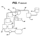
- FIG. 1 shows a fluid management system 10' in accordance with the prior art and includes those components necessary to simultaneously fill and drain a body cavity 12', such as the uterus, with a liquid for distending the body cavity.
- the liquid may also be used for removing surgical debris, blood and exudate from the cavity 12' during surgery via a continuous flow into and out of the cavity 12'.
- the fluid is pumped to the cavity 12' by a pump 14' which is fed by a suitable reservoir 16' of sterile fluid, such as isotonic saline solution. Fluid pumped to the cavity 12' fills and distends it to facilitate performing a surgical procedure therein.
- a vacuum source 18' provides suction under the control of a vacuum regulator 20' to aid in withdrawing fluid from the cavity 12'.
- the regulator 20' acts through a flow-back filter 22' which prevents fluid withdrawn from the cavity 12' from flowing into the vacuum regulator 20' or the vacuum source 18'.
- the foregoing arrangement is used to establish a constant flow of fluid to and from the cavity 12' and thereby establishes an equilibrium fluid level and pressure in the cavity 12'.
- a plurality of receptacles 24', 26' may be provided to receive waste fluid that has been withdrawn from the cavity 12'.
- these fluid receptacles are arranged in series and provide some convenient and sanitary method and apparatus for disposal of the wasted surgical fluid, such as by using removable plastic liners and the like.
- the present invention is shown to include a fluid management system 30 having a pump 32 preferably controlled by a feedback control loop as described below. Fluid is drawn from the reservoir 16 and pumped through a flow dampener 34 which smooths the output pressure variations of the pump 32.
- Pump 32 is typically a peristaltic type pump utilizing a plurality of rollers that sequentially compress a tube to impart motion to the fluid while preserving sterility of the fluid.
- the flow dampener 34 preferably includes a pressure sensor 36 for sensing pressure within the flow dampener 34 and a flow sensor 38 to sense the presence of fluid passing through the flow dampener 34.
- Both sensors 36, 38 preferably communicate their data output to a microprocessor controller 40 that may then utilize that sensor information to control the speed and/or cycle time of the pump 32.
- pressure and flow data may be displayed on a visual indicator to cue an operator to adjust the pump 32.
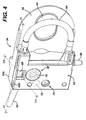
- the pump 32 may be equipped with its own pressure sensing probe and pressure responsive controller as more fully described in reference to FIG. 4.
- a user interface 42 is preferably provided which may include a monitor to display the pressure and flow sensed by the pressure sensor 36 and flow sensor 38, as well as the present output volume of the pump 32.
- the user interface 42 would typically also include a keyboard or other input device for setting the parameters of system 30 operation.
- a plurality of receptacles 24, 26 receive the waste fluid from the cavity 12 for temporary storage and disposal.
- a flow-back filter 23 is provided in the vacuum line drawing fluid from the cavity 12 and a separate flow-back filter 25 is provided in the drape vacuum line.
- a regulator valve 44 which may be manually or automatically controlled by the controller 40, controls the presence of vacuum on the vacuum side of the system by connecting or disconnecting with the vacuum source 18. Vacuum present when the valve 44 is open is regulated by the vacuum controller 46 which will be described further below.
- the vacuum controller 46 acts in cooperation with a vacuum sensor 48 and a vent valve 50 to provide the appropriate amount of vacuum required to maintain the desired fluid level and pressure in the cavity 12, given the inflow established by the pump 32.
- the vacuum sensor 48 preferably provides vacuum data to the controller 40 which then controls the operation of the vacuum controller 46 and vent valve 50, e.g., by varying the time that vacuum is applied to the flow-back filters 23 and 25 as shall be described further below.
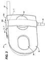
- FIG. 3 shows the flow dampener 34 having a pressure chamber 52 which is supplied with fluid by inlet tube 54. Fluid exiting the pressure chamber 52 does so via outlet fitting 56.
- the pressure chamber 52 is formed by joining a pair of hollow mating members 52a and 52b and includes on the face thereof an indentation 62 to enable the user thereof to grip the flow dampener 34.
- the flow dampener 34 Distal to the pressure chamber 52, the flow dampener 34 has a coupling plate 58 and a rotor opening 60 that enables the dampener to be fitted to a standard peristaltic pump as can be appreciated more fully in reference to FIGS. 4 and 6.
- the flow dampener 34 includes a tubing section 64 having a u-shaped configuration that communicates with the inlet tube 54.
- the u-shaped section 64 interacts with the rollers 66 of a peristaltic pump, as shown diagrammatically in FIG. 6.
- a window 60 permits the rollers 66 to engage tubing 64.
- the pressure sensor 36 includes a pressure sensing diaphragm 70 that is distended or displaced outwardly by pressure internal to pressure chamber 52. The external distension of the pressure sensing diaphragm 70 is sensed by a pressure probe shaft 72 associated with the peristaltic pump to which the dampener 34 is fitted.
- the sensed pressure is used for controlling the motor of the pump to maintain a particular pressure automatically, viz., if sensed pressure drops below the setpoint, the pump 32 is turned on. If sensed pressure exceeds the setpoint, the pump 32 is turned off.
- the foregoing pressure sensing and control feedback arrangement operates either in isolation or in cooperation with the digital controller 40 of FIG. 2.
- a fluid detection window 68 is provided in an upper portion of the pressure chamber shell 52b proximate to the inlet tube 54 which is preferably clear or light transmissive material.
- the fluid detection window 68 is utilized with an optical sensor described further below for determining if fluid fills the inlet tube 54.
- the pressure chamber 52 has an air vent 74 that is used to vent the chamber 52 of excess air and to allow the fluid to rise to a specific level within the chamber 52, as described further below.
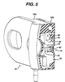
- FIG. 5 shows a first dampener 34 embodiment with an air vent 74 for maintaining a predetermined fluid level within the pressure chamber 52.
- a hydrophobic micropore filter 76 permits air to flow therethrough allowing the fluid 78 level to rise to just cover the hydrophobic filter 76.
- a one way valve 80 e.g., a mushroom valve, prevents air from entering the pressure chamber 52 in response to negative pressure therein.
- the fluid 78 traps a pocket of air 86 thereabove, with gravity maintaining this stratified air/fluid separation.
- the pocket of air 86 exhibits the expected pressure/volume relationship at room temperature in accordance with Boyle's law.
- the air pocket 86 With increased fluid input, the air pocket 86 becomes pressurized and this pressure is transmitted to the pressure sensor 36 (i.e., the pressure sensing diaphragm 70). Because the air pocket 86 is compressible, unlike the fluid 78, variations in output volume from the pump 32 (i.e., due to turning rollers 66 which sequentially squeeze down upon the u-shaped section 64) are smoothed by the air pocket 86, which acts like a cushion. More specifically, the fluid exiting the pressure chamber 52 is propelled therefrom by the pressure prevailing in the air pocket 86. Small variations in pump 32 output volume to the pressure chamber 52 do not cause significant variations in pressure in the air pocket 86. As a consequence, fluid output from the pressure chamber 52 is more constant. The air pocket 86 also retains gases that are contained in the fluid, thereby avoiding pumping gases in the fluid to the surgical site.
- FIG. 6 shows the interaction of the rollers 66 of a peristaltic pump 32 with the u-shaped section 64 of tubing, such interaction inducing a flow of fluid in the direction of the arrows shown.
- fluid flows into the inlet tube 54 and through the u-shaped section 64 into the pressure chamber 52.
- a pair of baffles 82, 84 are shown positioned around a fluid inlet 85 of the pressure chamber 52.
- the baffles 82, 84 induce a fluid flow in an upward direction and prevent the in-flowing fluid to flow out the outlet directly, thereby permitting air or other gases entrained in the fluid to rise through the fluid 78 into the upper portion of the pressure chamber 52 (i.e., into the air pocket 86).
- FIG. 7 shows how a flow sensor 38 (see FIG. 2) may be incorporated into the flow dampener 34 of the present invention.
- a light-emitting element 90 such as a light bulb or LED
- the light emitted by the element 90 is transmitted through the light-transmissive tubing 88 and strikes a reflective surface or mirror 94 on the other side of the tubing 88.
- Light reflected from the mirror 94 is retransmitted through the tubing 88 and strikes a light-sensing element 92, such as a photodiode or phototransistor, that converts the incoming light signal to a voltage level or current flow.
- the foregoing light sensing arrangement will operate, namely, that light emitted by the element 90 will pass through the tubing 88, if it is empty, in a diffuse manner and will strike the mirror 94 and diffuse even further, such that the return signal to the light-sensing element 92 will be weak (see FIG. 9).
- the tubing 88 is filled with fluid as shown in FIG. 8, it will act as a lens, focusing the light signal from the light-emitting element 90 on the reflective surface 94 such that the signal retransmitted from the mirror 94 will be likewise focused on the light-sensing element 92 and will have a much greater magnitude than if the tubing 88 were empty.
- the light signal received at the light-sensing element 92 can then be processed by suitable circuitry, e.g., like that shown in FIG. 10, to interpret the variation in light magnitude to indicate the presence of fluid in the tubing 88 or the lack of fluid.
- FIG. 10 shows a circuit 91 having a light-emitting element 90 (in the form of a light-emitting diode) and a light-sensing element 92 (in the form of a phototransistor), which would by physically juxtaposed as shown in FIG. 7.
- the voltage at point 93 will vary depending on the current flow through the light-sensing element (i.e., phototransistor) 92 as determined by the presence or absence of fluid in tubing 88 (see FIG. 7) and the corresponding magnitude of light transmitted to the light-sensing element (i.e., phototransistor) 92.
- the voltage level at 93 is compared with a reference voltage and the difference amplified by operational amplifier 95, the output of which is the signal representing the presence or absence of fluid in the tubing 88.
- FIG. 11 shows an alternative embodiment for a fluid detector 96 in accordance with the present invention which includes a body 98 having a tube receptacle 100 formed therein.
- the tube receptacle 100 slidably receives a tube (not shown) which can be flattened slightly and inserted into the narrowed portion of the tube receptacle 100 and then allowed to relax and assume its normal cylindrical shape.
- a light-emitting element 90 can be placed on one side of the tubing.
- the light-sensing elements 92a, 92b spatially separated such that if a diffuse transmission of light through the tube results, namely if the tube is empty, then both of the spaced light-sensing elements 92a, 92b will receive the light transmission. Otherwise, if the transmission is focused due to the presence of fluid in the tube, then only the light-sensing element 92b will be exposed to the light transmission.
- the signals received by the light-sensing elements 92a, 92b can be compared, amplified, etc. in order to convey a signal indicative of the presence or absence of fluid in a tube about which the detector 96 is positioned.
- FIGS. 12, 13 and 14 show variations of the flow dampener 34 described above, with FIG. 12 having a modified baffle 182 which causes the input flow to reverse direction.
- a hydrophobic micropore filter 174 determines fluid level in the pressure chamber 152.
- the hydrophobic micropore filter of the previous embodiments has been replaced by an upper air vent orifice 274 which is stoppered and unstoppered depending upon the fluid level 278 within the pressure chamber 252 which lifts float 277 and plug 279 to close the air vent 274.
- the hydrophobic micropore filter has been replaced with an air vent 374 that is controlled by a needle valve 379, the position of which is responsive to fluid level 378 which urges float 377 up and down.
- the buoyancy of float 377 is counterbalanced by a pair of pistons 381, 383, each having different cross-sectional areas and thereby applying different counteracting forces on a shaft 389 that couples the pistons 381, 383 and attaches to the float 377.
- a common cylinder sleeve 385 which includes upper and lower mating cylinder bores, vents centrally to the atmosphere via a vent 387.
- a mechanical vacuum regulator regulates a pressure common to multiple fluid receptacles, i.e., those going to the fluid receptacles 24', 26', as well as to the drape system 28'.
- the large volume of flow attributable to the drape system 28' overpowers the common regulator dropping the vacuum level to the fluid receptacles 24', 26' until the drape suction is turned off.
- vacuum regulators are sometimes ineffective in supplying a well-regulated high volume flow and often vent very slowly if the vacuum is too high.
- the vacuum level is sensed at the regulator, therefore vacuum drops through the flow-back filter 22', the receptacles 24', 26' and their associated tubing are not compensated for in regulating the vacuum.
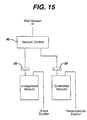
- FIG. 15 diagrammatically shows that the vacuum controller 46 of the present invention provides controlled vacuum to the body cavity 12 (resectoscope suction), but uncontrolled vacuum to the surgical drape where maintenance of controlled vacuum is less critical.
- the present invention thus utilizes prioritized vacuum sharing wherein the vacuum controller 46 maintains a regulated vacuum in the fluid receptacles 24, 26 connected to the resectoscope. Any remaining vacuum is routed to the drape suction once sufficient vacuum is directed to the fluid receptacles 24, 26. This eliminates the problem of an open drape suction overpowering the ability to maintain a good regulated vacuum.
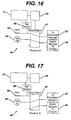
- the valve means for performing the foregoing are described below in reference to FIGS. 16 and 17.
- FIGS. 16 and 17 show the vacuum controller 46 equipped with a high capacity spool valve 47 actuated by actuator 49 under the control of microprocessor 51 based upon signals representing vacuum magnitude received from the vacuum sensor 48.
- the controlled vacuum outlet is connected to the vacuum sensor 48 and the vent valve 50.
- the vacuum appearing at regulator valve 44 is connected to the spare vacuum output connected to the flow-back filter 25 leading to the drape. If the vent valve 50 is open in this position, it will vent the controlled vacuum. If the vent valve 50 is closed, the vacuum sensor 48 can measure the vacuum in the controlled vacuum receptacles 24, 26 with no flow and therefore no erroneous vacuum readings.
- the present invention recognizes the fact that when vacuum is applied to the receptacles 24, 26, there is significant pressure drop through the flow-back filter 23 and the tubing to the receptacles 24, 26.
- the present invention samples the vacuum pressure only when the flow is stopped so that the vacuum controller 46 can operate based on a more accurate vacuum reading.
- a software algorithm in microprocessor 51 switches the spool valve 49 between position A and position B periodically, e.g., once per second.
- the amount of time the valve 47 is in position B, supplying vacuum to the controlled receptacles 24, 26, is based upon the last vacuum measurement made in position B.
- the software can determine how long to next hold the spool valve 47 in position B to achieve and maintain a given vacuum level in the controlled vacuum receptacles 24, 26.
- the low restriction spool valve 47 allows quick changes in the vacuum level in the controlled vacuum receptacles 24, 26.
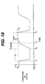
- the inclusion of the vent valve 50 makes increasing the pressure (bleeding off vacuum) quick as well. This relationship is depicted graphically in FIG. 18.
- FIG. 18 shows the vacuum present in the receptacle 26 as a function of time and as a result of the intermittent connection of the flow-back filter 23 to the vacuum source 18 via the vacuum controller 46 and more specifically the spool valve 47.
- the spool valve 47 is placed in position B (see FIG. 17), whereupon the vacuum directed to cavity 12 increases rapidly (drop in pressure).
- the spool valve 47 is held in position B until time t 2 , when it is cycled to position A (see FIG. 16).
- Time period t 1 to t 2 can be described as the time the cavity 12 suction is exposed to input vacuum or t v .
- the change of position of the spool valve 47 from position B to position A is not instantaneous but rather occurs over a transition period t trans extending from time t 2 to t 3
- the vacuum present in elements i.e., the flow-back filter 23 and the reservoirs 24, 26
- the time period from t 3 to t 4 when the vacuum source 18 is isolated from the flow-back filter 23 may be called t off .
- t off a vacuum drop (raise in pressure) ⁇ p is experienced.
- the foregoing process is repeated cyclically such that the number of complete cycles from t 1 to t 4 over a reference time period is the frequency.
- the objective then is to vary the pulse widths representing the times when the spool valve 47 is alternately in positions B and A so that the approximate average or intermediate pressure P i during t off approximates the set point pressure P s .
- This can be accomplished under algorithmic control by interactively measuring the vacuum and adjusting t v such that P i approximates P s .
- System capacity varies depending upon the number of receptacles 24, 26 chained together and the level of fluid fill in each.
- the control loop evaluates the ratio of ⁇ p/t v and uses this in a difference equation to compute the next t v in order to achieve a desired vacuum level.
- the slope of vacuum drop over time t off is a measure of air flow.
- the control algorithm preferably maintains a maximum ⁇ p difference within some minimum valve cycle time.
- variable t v is computed based on the last observed ⁇ p and the desired ⁇ p. A pulse may be skipped to vent vacuum. Maximum t v must be less than the repetition rate so that ⁇ p can be measured, i.e., a minimum t off time is required at least once per/period. Once t off is at minimum, the vacuum flow is maxed out.
Landscapes
- Health & Medical Sciences (AREA)
- Heart & Thoracic Surgery (AREA)
- General Health & Medical Sciences (AREA)
- Public Health (AREA)
- Anesthesiology (AREA)
- Hematology (AREA)
- Life Sciences & Earth Sciences (AREA)
- Animal Behavior & Ethology (AREA)
- Engineering & Computer Science (AREA)
- Biomedical Technology (AREA)
- Veterinary Medicine (AREA)
- Vascular Medicine (AREA)
- Pulmonology (AREA)
- Physics & Mathematics (AREA)
- Fluid Mechanics (AREA)
- Surgery (AREA)
- External Artificial Organs (AREA)
- Reciprocating Pumps (AREA)
Applications Claiming Priority (2)
| Application Number | Priority Date | Filing Date | Title |
|---|---|---|---|
| US497221 | 2000-01-31 | ||
| US09/497,221 US6595957B1 (en) | 2000-01-31 | 2000-01-31 | Surgical fluid management system with a dampening chamber |
Publications (2)
| Publication Number | Publication Date |
|---|---|
| EP1129732A2 true EP1129732A2 (de) | 2001-09-05 |
| EP1129732A3 EP1129732A3 (de) | 2003-07-16 |
Family
ID=23975953
Family Applications (1)
| Application Number | Title | Priority Date | Filing Date |
|---|---|---|---|
| EP01300800A Withdrawn EP1129732A3 (de) | 2000-01-31 | 2001-01-30 | Chirurgisches Flüssigkeitsbehandlungssystem mit einer dämpfenden Kammer |
Country Status (2)
| Country | Link |
|---|---|
| US (1) | US6595957B1 (de) |
| EP (1) | EP1129732A3 (de) |
Cited By (2)
| Publication number | Priority date | Publication date | Assignee | Title |
|---|---|---|---|---|
| WO2006059189A1 (en) * | 2004-11-30 | 2006-06-08 | Atul Kumar | A system of dampening pressure pulsations caused by a positive displacement pump in endoscopic surgery |
| WO2025101948A1 (en) * | 2023-11-09 | 2025-05-15 | Boston Scientific Scimed, Inc. | Disposable fluid cassette for fluid management system |
Families Citing this family (60)
| Publication number | Priority date | Publication date | Assignee | Title |
|---|---|---|---|---|
| US6673098B1 (en) * | 1998-08-24 | 2004-01-06 | Radiant Medical, Inc. | Disposable cassette for intravascular heat exchange catheter |
| US20080154214A1 (en) * | 2006-12-22 | 2008-06-26 | Medrad, Inc. | Flow Based Pressure Isolation and Fluid Delivery System Including Flow Based Pressure Isolation |
| GB2414402B (en) | 2004-05-28 | 2009-04-22 | Cilag Ag Int | Injection device |
| GB2414409B (en) | 2004-05-28 | 2009-11-18 | Cilag Ag Int | Injection device |
| GB2414400B (en) | 2004-05-28 | 2009-01-14 | Cilag Ag Int | Injection device |
| GB2414404B (en) | 2004-05-28 | 2009-06-03 | Cilag Ag Int | Injection device |
| GB2414401B (en) | 2004-05-28 | 2009-06-17 | Cilag Ag Int | Injection device |
| GB2414399B (en) | 2004-05-28 | 2008-12-31 | Cilag Ag Int | Injection device |
| GB2414775B (en) | 2004-05-28 | 2008-05-21 | Cilag Ag Int | Releasable coupling and injection device |
| GB2414405B (en) * | 2004-05-28 | 2009-01-14 | Cilag Ag Int | Injection device |
| US7510397B2 (en) * | 2004-10-15 | 2009-03-31 | Hochman Mark N | Method and apparatus for performing maxillary sinus elevation |
| GB2424838B (en) | 2005-04-06 | 2011-02-23 | Cilag Ag Int | Injection device (adaptable drive) |
| GB2424835B (en) | 2005-04-06 | 2010-06-09 | Cilag Ag Int | Injection device (modified trigger) |
| GB2427826B (en) | 2005-04-06 | 2010-08-25 | Cilag Ag Int | Injection device comprising a locking mechanism associated with integrally formed biasing means |
| GB2425062B (en) | 2005-04-06 | 2010-07-21 | Cilag Ag Int | Injection device |
| GB2424836B (en) | 2005-04-06 | 2010-09-22 | Cilag Ag Int | Injection device (bayonet cap removal) |
| ATE452670T1 (de) | 2005-08-30 | 2010-01-15 | Cilag Gmbh Int | Nadelvorrichtung für eine vorgefüllte spritze |
| US20110098656A1 (en) | 2005-09-27 | 2011-04-28 | Burnell Rosie L | Auto-injection device with needle protecting cap having outer and inner sleeves |
| CN101370534B (zh) * | 2005-12-14 | 2012-03-07 | 史赛克公司 | 医疗/手术废物收集和处理系统 |
| EP2008591B1 (de) * | 2006-04-07 | 2015-09-09 | Hitachi Medical Corporation | Ultraschallsonde und sonografiegerät |
| GB2438593B (en) | 2006-06-01 | 2011-03-30 | Cilag Gmbh Int | Injection device (cap removal feature) |
| GB2438590B (en) | 2006-06-01 | 2011-02-09 | Cilag Gmbh Int | Injection device |
| GB2438591B (en) | 2006-06-01 | 2011-07-13 | Cilag Gmbh Int | Injection device |
| US8409441B2 (en) | 2007-02-27 | 2013-04-02 | Deka Products Limited Partnership | Blood treatment systems and methods |
| KR20230165373A (ko) | 2007-02-27 | 2023-12-05 | 데카 프로덕츠 리미티드 파트너쉽 | 혈액투석 시스템 |
| US9028691B2 (en) | 2007-02-27 | 2015-05-12 | Deka Products Limited Partnership | Blood circuit assembly for a hemodialysis system |
| WO2009094184A1 (en) | 2008-01-23 | 2009-07-30 | Deka Products Limited Partnership | Fluid volume determination for medical treatment system |
| US11833281B2 (en) | 2008-01-23 | 2023-12-05 | Deka Products Limited Partnership | Pump cassette and methods for use in medical treatment system using a plurality of fluid lines |
| TW200940119A (en) | 2008-01-25 | 2009-10-01 | Smiths Medical Asd Inc | Gas vent valve assembly |
| GB2461086B (en) | 2008-06-19 | 2012-12-05 | Cilag Gmbh Int | Injection device |
| GB2461087B (en) | 2008-06-19 | 2012-09-26 | Cilag Gmbh Int | Injection device |
| GB2461089B (en) | 2008-06-19 | 2012-09-19 | Cilag Gmbh Int | Injection device |
| GB2461084B (en) | 2008-06-19 | 2012-09-26 | Cilag Gmbh Int | Fluid transfer assembly |
| GB2461085B (en) | 2008-06-19 | 2012-08-29 | Cilag Gmbh Int | Injection device |
| US9474848B2 (en) | 2009-03-09 | 2016-10-25 | Thermedx, Llc | Fluid management system |
| CA2754773C (en) * | 2009-03-09 | 2017-06-13 | Thermedx, Llc | Surgical fluid management system having default operating parameters associated with a plurality of medical procedures |
| WO2012006425A2 (en) * | 2010-07-07 | 2012-01-12 | Deka Products Limited Partnership | Medical treatment system and methods using a plurality of fluid lines |
| JP6109819B2 (ja) | 2011-05-24 | 2017-04-05 | デカ・プロダクツ・リミテッド・パートナーシップ | 血液透析システム |
| AU2013235701B2 (en) | 2012-03-17 | 2017-02-09 | Johnson & Johnson Surgical Vision, Inc. | Surgical cassette |
| GB2517896B (en) | 2013-06-11 | 2015-07-08 | Cilag Gmbh Int | Injection device |
| GB2515038A (en) | 2013-06-11 | 2014-12-17 | Cilag Gmbh Int | Injection device |
| GB2515039B (en) | 2013-06-11 | 2015-05-27 | Cilag Gmbh Int | Injection Device |
| GB2515032A (en) | 2013-06-11 | 2014-12-17 | Cilag Gmbh Int | Guide for an injection device |
| US9770541B2 (en) | 2014-05-15 | 2017-09-26 | Thermedx, Llc | Fluid management system with pass-through fluid volume measurement |
| MX2023002575A (es) | 2014-06-05 | 2023-03-13 | Deka Products Lp | Sistema para calcular un cambio en volumen de fluido en una camara de bombeo. |
| CN109328039B (zh) | 2016-04-25 | 2022-02-22 | 英特格拉生命科技企业责任有限合伙公司 | 用于超声吸引外科手术变幅杆的流道 |
| USD820441S1 (en) | 2016-06-13 | 2018-06-12 | Integra Lifesciences Nr Ireland Limited | Surgical handpiece nosecone |
| USD819195S1 (en) * | 2016-10-11 | 2018-05-29 | Integra Lifesciences Nr Ireland Limited | Tubing cartridge for an ultrasonic surgical aspirator |
| US12109352B2 (en) | 2016-05-20 | 2024-10-08 | Integra Lifesciences Enterprises, Lllp | Ergonomic tubing attachment for medical apparatus |
| WO2017203408A1 (en) | 2016-05-24 | 2017-11-30 | Integra Lifesciences Nr Ireland Limited | Ergonomic tubing attachment for medical apparatus |
| AU2017362062B2 (en) | 2016-11-16 | 2023-03-23 | Integra Lifesciences Enterprises, Lllp | Ultrasonic surgical handpiece |
| US10687840B1 (en) | 2016-11-17 | 2020-06-23 | Integra Lifesciences Nr Ireland Limited | Ultrasonic transducer tissue selectivity |
| US11607489B2 (en) | 2017-05-26 | 2023-03-21 | Bayer Healthcare Llc | Injector state logic with hemodynamic monitoring |
| EP4115919B1 (de) | 2018-12-19 | 2024-01-31 | Boston Scientific Scimed, Inc. | Dämpfungselement für fluidverwaltungssystem |
| AU2020306056B2 (en) | 2019-06-27 | 2022-11-24 | Boston Scientific Scimed, Inc. | Detection of an endoscope to a fluid management system |
| EP3782528B1 (de) * | 2019-08-23 | 2023-04-19 | Chang Gul Hong | Fluidzuführungsvorrichtung für endoskop |
| WO2021092424A1 (en) | 2019-11-08 | 2021-05-14 | Thermedx Llc | Fluid management systems and methods |
| CN121265900A (zh) | 2020-01-30 | 2026-01-06 | 波士顿科学医学有限公司 | 流体管理系统 |
| KR20250122530A (ko) | 2020-02-27 | 2025-08-13 | 보스톤 싸이엔티픽 싸이메드 인코포레이티드 | 유체 관리 및 의료 디바이스 시스템의 파라미터를 제어하기 위한 방법 |
| USD1115053S1 (en) | 2023-11-09 | 2026-02-24 | Boston Scientific Scimed, Inc. | Fluid cassette for a fluid management system |
Family Cites Families (22)
| Publication number | Priority date | Publication date | Assignee | Title |
|---|---|---|---|---|
| US3833018A (en) | 1973-02-21 | 1974-09-03 | Pass Port Syst Corp | Low leakage vacuum valve and chamber using same |
| GB1501883A (en) | 1973-05-08 | 1978-02-22 | Nat Res Dev | Devices for use in monitoring chemical reactions |
| US4108207A (en) | 1977-04-13 | 1978-08-22 | The United States Of America As Represented By The United States Department Of Energy | Multiple-port valve |
| US4312341A (en) | 1979-12-13 | 1982-01-26 | Baxter Travenol Laboratories, Inc. | Bubble detector |
| US4344429A (en) | 1979-12-13 | 1982-08-17 | Baxter Travenol Laboratories, Inc. | Bubble detector with feedback circuit for improved sensitivity |
| US4399711A (en) | 1980-04-18 | 1983-08-23 | Beckman Instruments, Inc. | Method and apparatus ensuring full volume pickup in an automated pipette |
| DE3338758C2 (de) * | 1983-10-21 | 1986-09-11 | Hubert Dipl.-Ing. 1000 Berlin Fuchs | Vorrichtung zur Perfusion von Körperhöhlen mit einer Flüssigkeit |
| US4810242A (en) | 1985-09-26 | 1989-03-07 | Alcon Laboratories Inc. | Surgical cassette proximity sensing and latching apparatus |
| EP0222574B1 (de) | 1985-11-01 | 1996-04-03 | The Director General Of The Ministry Of Agriculture And Fisheries | Melkmaschinen |
| US5045077A (en) * | 1985-11-25 | 1991-09-03 | Blake Joseph W Iii | Body cavity drainage implement |
| US4816695A (en) * | 1987-08-31 | 1989-03-28 | Lavin Thomas N | Optical fluid detector |
| US5152746A (en) * | 1990-04-30 | 1992-10-06 | Zimmer, Inc. | Low pressure irrigation system |
| US5399160A (en) * | 1991-10-04 | 1995-03-21 | Minnesota Mining And Manufacturing Company | Irrigation tubing set having compliant sections |
| DE69432582T2 (de) | 1993-10-28 | 2003-11-27 | Medrad, Inc. | System zur Administration von Flüssigkeiten bei mehreren Patienten |
| US5520638A (en) * | 1995-03-28 | 1996-05-28 | Arthrex, Inc. | Main pump tubing for arthroscopy infusion pump |
| US5741237A (en) * | 1995-04-10 | 1998-04-21 | Walker; Kenneth Gordon | System for disposal of fluids |
| US5685851A (en) * | 1995-06-06 | 1997-11-11 | Eams Industries, Inc. | Irrigation syringe |
| DE69631068T2 (de) | 1995-11-01 | 2004-06-03 | Ethicon, Inc. | System zur regelung der flüssigkeitsrückhaltung |
| US6152902A (en) | 1997-06-03 | 2000-11-28 | Ethicon, Inc. | Method and apparatus for collecting surgical fluids |
| JP2000014693A (ja) | 1998-06-30 | 2000-01-18 | Nidek Co Ltd | 灌流吸引装置 |
| US6206014B1 (en) * | 1999-03-26 | 2001-03-27 | American Optisurgical Incorporated | Automated system for rinsing a fluid line of a medical system |
| US6396583B1 (en) | 2000-01-31 | 2002-05-28 | Ethicon, Inc. | Optical fluid sensor |
-
2000
- 2000-01-31 US US09/497,221 patent/US6595957B1/en not_active Expired - Lifetime
-
2001
- 2001-01-30 EP EP01300800A patent/EP1129732A3/de not_active Withdrawn
Cited By (3)
| Publication number | Priority date | Publication date | Assignee | Title |
|---|---|---|---|---|
| WO2006059189A1 (en) * | 2004-11-30 | 2006-06-08 | Atul Kumar | A system of dampening pressure pulsations caused by a positive displacement pump in endoscopic surgery |
| US7678070B2 (en) | 2004-11-30 | 2010-03-16 | Atul Kumar | System of dampening pressure pulsations caused by a positive displacement pump in endoscopic surgery |
| WO2025101948A1 (en) * | 2023-11-09 | 2025-05-15 | Boston Scientific Scimed, Inc. | Disposable fluid cassette for fluid management system |
Also Published As
| Publication number | Publication date |
|---|---|
| EP1129732A3 (de) | 2003-07-16 |
| US6595957B1 (en) | 2003-07-22 |
Similar Documents
| Publication | Publication Date | Title |
|---|---|---|
| US6595957B1 (en) | Surgical fluid management system with a dampening chamber | |
| US7204821B1 (en) | Surgical fluid management system with suction control | |
| US6396583B1 (en) | Optical fluid sensor | |
| EP2032185B1 (de) | KASSETTE FÜR CHIRURGISCHE EINGRIFFE AM AUGE mit mindestens einer sich verjüngenden Führungsnute | |
| US8801654B2 (en) | Method and device for irrigation of body cavities | |
| EP1996269B1 (de) | Chirurgiekassette mit mehrbereichsflüssigkeitskammer | |
| US5563584A (en) | Liquid level sensing and monitoring system for medical fluid infusion systems | |
| MX2007015969A (es) | Sistema y metodo para controlar el flujo de fluidos en una camara de aspiracion. | |
| EP1314441A1 (de) | Wegwerfbares Wasserschloss mit Vakuumregulierung für eine Thorax-Drainage | |
| EP3474916B1 (de) | Körperdrainagevorrichtung | |
| US20050245903A1 (en) | Method and apparatus for controllably aspirating fluids from surgical sites | |
| AU2013201226B2 (en) | A cassette for use with an ophthalmic surgery pump | |
| HK1130706B (en) | Ophthalmic surgical cassette comprising at least a tapered aligment slot | |
| HK1157684A (en) | Ophthalmic surgical cassette and system | |
| HK1168563B (en) | Ophthalmic surgical cassette |
Legal Events
| Date | Code | Title | Description |
|---|---|---|---|
| PUAI | Public reference made under article 153(3) epc to a published international application that has entered the european phase |
Free format text: ORIGINAL CODE: 0009012 |
|
| AK | Designated contracting states |
Kind code of ref document: A2 Designated state(s): AT BE CH CY DE DK ES FI FR GB GR IE IT LI LU MC NL PT SE TR |
|
| AX | Request for extension of the european patent |
Free format text: AL;LT;LV;MK;RO;SI |
|
| PUAL | Search report despatched |
Free format text: ORIGINAL CODE: 0009013 |
|
| AK | Designated contracting states |
Designated state(s): AT BE CH CY DE DK ES FI FR GB GR IE IT LI LU MC NL PT SE TR |
|
| AX | Request for extension of the european patent |
Extension state: AL LT LV MK RO SI |
|
| RIC1 | Information provided on ipc code assigned before grant |
Ipc: 7A 61M 3/02 B Ipc: 7A 61M 1/00 A |
|
| 17P | Request for examination filed |
Effective date: 20040108 |
|
| AKX | Designation fees paid |
Designated state(s): AT BE CH CY DE DK ES FI FR GB GR IE IT LI LU MC NL PT SE TR |
|
| STAA | Information on the status of an ep patent application or granted ep patent |
Free format text: STATUS: THE APPLICATION IS DEEMED TO BE WITHDRAWN |
|
| 18D | Application deemed to be withdrawn |
Effective date: 20060927 |