EP1129747A2 - Elément formant câle inclinée utilisé dans une fixation de surf - Google Patents
Elément formant câle inclinée utilisé dans une fixation de surf Download PDFInfo
- Publication number
- EP1129747A2 EP1129747A2 EP01420033A EP01420033A EP1129747A2 EP 1129747 A2 EP1129747 A2 EP 1129747A2 EP 01420033 A EP01420033 A EP 01420033A EP 01420033 A EP01420033 A EP 01420033A EP 1129747 A2 EP1129747 A2 EP 1129747A2
- Authority
- EP
- European Patent Office
- Prior art keywords
- element according
- plate
- plates
- face
- inclination
- Prior art date
- Legal status (The legal status is an assumption and is not a legal conclusion. Google has not performed a legal analysis and makes no representation as to the accuracy of the status listed.)
- Granted
Links
Images


Classifications
-
- A—HUMAN NECESSITIES
- A63—SPORTS; GAMES; AMUSEMENTS
- A63C—SKATES; SKIS; ROLLER SKATES; DESIGN OR LAYOUT OF COURTS, RINKS OR THE LIKE
- A63C10/00—Snowboard bindings
- A63C10/28—Snowboard bindings characterised by auxiliary devices or arrangements on the bindings
- A63C10/285—Pads as foot or binding supports, e.g. pads made of foam
-
- A—HUMAN NECESSITIES
- A63—SPORTS; GAMES; AMUSEMENTS
- A63C—SKATES; SKIS; ROLLER SKATES; DESIGN OR LAYOUT OF COURTS, RINKS OR THE LIKE
- A63C10/00—Snowboard bindings
- A63C10/16—Systems for adjusting the direction or position of the bindings
- A63C10/22—Systems for adjusting the direction or position of the bindings to fit the size of the shoe
-
- A—HUMAN NECESSITIES
- A63—SPORTS; GAMES; AMUSEMENTS
- A63C—SKATES; SKIS; ROLLER SKATES; DESIGN OR LAYOUT OF COURTS, RINKS OR THE LIKE
- A63C10/00—Snowboard bindings
- A63C10/16—Systems for adjusting the direction or position of the bindings
- A63C10/18—Systems for adjusting the direction or position of the bindings about a vertical rotation axis relative to the board
Definitions
- the invention relates to the field of sliding sports and more specifically that snowboarding or snowboarding. It relates more particularly to an element interface set up between the ends of the sole of the shoe and the binding or the surfboard, to fill the empty space between the sole and fixing or plank. Such interface elements are commonly called in the field of snowboarding by the English expression of "gas pedal”.
- the soft shoes have a sole that has a slight curvature such that the front and rear ends are slightly raised.
- One of the problems which the invention therefore proposes to solve is that of optimizing the contact between the wedge element and the sole of the shoe, to obtain the best possible transmission of forces, and whatever the shoe size and geometry.
- the invention therefore relates to a wedge element, intended to be secured to the front or rear end of the base of a surfboard binding, or directly to the upper face of the surfboard.
- This element has a top side intended to receive the supports from the front or rear end of the sole of the shoe.
- This element forming an inclined wedge comprises means for adjusting the angle. inclination, measured in a longitudinal plane, between the upper face of the wedge inclined and the upper face of the board, so as to be adaptable to several shoe geometries.
- the wedge element is characterized in that it also includes means capable of adjusting the longitudinal position of the face upper of the shim relative to the base of the binding.
- the characteristic element has a variable geometry which allows to adapt to different types and sizes of shoe sole in completely filling the volume between the surfboard and the below the sole.
- the angle of inclination is measured in a longitudinal plane which is perpendicular to the board and in the direction of orientation of the foot. So, when the user changes shoes and the sole of their new shoes is more raised at the front end or longer, it just change the inclination of the upper face of the wedge, and the position longitudinal of the latter so that its supports are just as effectively transmitted only with the old setting.
- the characteristic element may also include means capable of adjusting the angle of inclination, measured in a transverse plane, between the upper face of the wedge and the upper face of the board, so as to adapt to a position of the shoe inclined transversely. In this way, it is possible to optimize the position of the foot by a transverse inclination or "canting", while keeping good transmission of support at the front end of the shoe.
- the bottom plate can be an integral part of the base, of which it then constitutes a forward extension.
- the element is completely separate from the base and comes into place on this, or even on the board, at the front end of the base.
- the means capable of adjusting the inclination of the two plates comprise at least one screw cooperating with the two lower and upper plates.
- the lower plate has a thread receiving said screw, and the upper plate rests on the head of this screw so that the latter works in compression.
- the upper plate may have a suitable housing to receive the head of the screw, this housing then having an opening opening on the upper face of the upper plate to allow access to said head screw. This prevents the elements from protruding from the upper side of the wedge.
- the lower plate includes a thread receiving the screw, and it is the head of the screw which rests on the plate upper, so that the screwing of the screw brings the upper plate relative to the lower plate, return means being arranged to oppose this rimpedement.
- recall means are sufficiently stiff in compression to prevent the shoe from tipping over when efforts are exerted.
- the top plate may have a vertical flap oriented towards the bottom plate, and able to close the opening between the two plates to limit the introduction of snow.
- the space between the two plates can be filled with a compressible foam, so as to prevent the introduction of snow.
- the means capable of adjusting the inclination may consist of a moving part, the position of which is indexed relative to to the lower plate, the upper zone of which comes into contact with the lower face of the upper plate to determine the inclination relative to the plate lower.
- the articulation of the two lower plates and upper can be achieved by a connecting member capable of pressing the two plates against each other.
- the upper plate advantageously has a curve at the level of the area of cooperation with said connecting member so as to allow the inclination of the plates between them. In this way, the tilting movement of the top plate is allowed without generating mechanical stresses on this plate.
- the contact areas of the lower plates and upper have additional notches capable of ensuring blocking in longitudinal position of the two plates relative to each other. In this way, we eliminates any risk of the top plate shifting relative to the plate lower when it is under stress.
- the lower plate has a groove longitudinal in which part of the connecting member can move for ensure the longitudinal adjustment of the upper plate relative to the plate lower, the locking in position being provided by the aforementioned notched areas.
- the shim may include two adjusting screws located on either side of the median longitudinal plane of the element, so that ensure a distribution of the efforts limiting the risks of rupture of the troubles of mechanical.
- the wedge may comprise a transverse blade cooperating with the two screws, so as to ensure a better distribution over the entire width of the shim of the forces exerted by the upper plate.
- the wedge may include a seal interposed between the lower and upper plates.
- a layer of plastic material capable of camouflaging the screw heads may be provided.
- the invention relates to a wedge element intended to be installed at the front and / or rear of a surfboard binding, to fill the volume between the upper face of the board and the underside of the sole, when it is curved upwards.
- a wedge element intended to be installed at the front and / or rear of a surfboard binding, to fill the volume between the upper face of the board and the underside of the sole, when it is curved upwards.
- Figures 1a, 1b and 2 to 5 relate to a first embodiment in which the front part of the base (1) constitutes one of the plates of the element feature. More precisely this base has in its center an opening (2) intended to receive the adjustment disc in orientation of the binding. The part chamfered (3) serves in effect for indexing the disc, not shown.
- the front part (4) of the base rests directly on the upper face (5) of the board.
- This front part (4) of the base forms in its extreme part at the front a lower plate (6) above which a recess is produced (7) allowing the establishment of the upper plate (8), so that the upper face (9) of this upper plate (8) is in continuity with the face upper (10) of the central part of the base.
- the upper plate (8) is limited at the front and rear by edges in an arc.
- the rear edge (12) is substantially centered on the center (13) of the binding, while the front edge (11) conforms to the shape of the foot and is therefore slightly further forward on the inside (15) of the foot.
- the upper plate (8) is secured to the lower plate (6) or the front end of the base by a connecting member (20) consisting of a screw (21) and a shoulder nut (22).
- the head (23) of the screw fits into a housing (24) provided for this purpose on the top of the upper plate (8) and the nut shoulder (22) has its zone (25) of larger diameter which is housed the interior of a groove (26) provided for this purpose under the underside (27) of the base corresponding to the bottom plate of the hold.
- the lesser part diameter (28) of the shoulder nut (22) can move in an opening longitudinal (29) formed inside the lower plate (6). In this way, the connecting member (20) and therefore the upper plate (8) can move longitudinally between the two positions illustrated in Figures la and 1b.
- Maintaining the position of the upper plate (8) relative to the plate lower (6) is effected on the one hand, by the tightening of the connecting member (20), and on the other hand, by the cooperation of the two facing surfaces (30, 31) which are advantageously notched.
- the upper plate (8) has an orientation capacity with respect to the lower plate (6) for adapt to different shoe geometries. This orientation is obtained by pivoting of the upper plate (8) relative to the lower plate (6) or the end of the base, around the connecting member (20). This is why, the parts (33, 34) of the lower face of the upper plate (8) located in front and behind the connecting member (20) are not coplanar, but present at otherwise a slight inclination, so that when the top plate (8) pivots around the connecting member (20), the part (33) of the upper plate (8) located at the rear of the connecting member (20) can approach the face upper (37) of the lower plate (6) corresponding to the limit of the offset (7).
- the front part of the upper plate (8) has a flap (45) directed downwards, and which arrives when the upper plate (8) is in the lowest position almost in contact with the upper face (5) of the board.
- the front part of the upper plate (8) comprises, in its zones lateral, two threads (46) inside which a threaded rod can be screwed (47) whose lower zone includes a washer (48) intended to come into contact of the upper face (5) of the board.
- the upper part of the threaded rod (47) is accessible by the upper face (9) of the upper plate (8) at a housing (49) provided for this purpose, and which can advantageously be closed by a stud (50) made of plastic.
- FIG. 6 illustrates an alternative embodiment in which the lower plate (60) extends up to the vicinity of the flap (61) of the upper plate (62).
- the lower plate (60) has a zone (63) including a thread (64) into which a screw (65) enters, the head (66) of which passes through the plate upper (62) at the level of a housing (67) provided for this purpose.
- the head (66) of the screw (65) can be accompanied by a washer (68) intended to ensure good distribution of forces at the shoulder (69) of the housing (67).
- Means of recall such as an elastic foam stud (70), or springs (not shown) oppose the movement of the upper plate (62) downwards.
- the longitudinal adjustment of the shim is obtained by modifying the position of the lower plate (60) relative to the base (71).
- the base (71) and the rear part (72) of the lower plate (60) have an overlap zone.
- the rear part (72) of the upper plate has a longitudinal lumen (73) through which a screw (74) is screwed into the front end of the base.
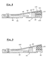
- FIG. 7 An alternative embodiment illustrated in FIG. 7 operates according to a principle mechanically close.
- the screw (75) which penetrates into the thread (64) of the plate lower (6) has a spherical head (76) which comes into contact with a housing (78) of complementary shape formed on the underside (79) of the plate upper (80).
- This housing (78) opens out through a smaller opening (81) diameter to allow access to the screw head (76).
- the screw head (76) supports the forces transmitted by the upper plate (80), and therefore works in compression.
- the shim may include also a transverse plate, bearing on the two screws so as to distribute the forces exerted on them evenly.
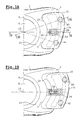
- FIGs 8 and 9 illustrate another embodiment of the invention, in which the bottom plate comprises an opening (92) inside which can pass a moving part (93). More specifically, the underside (94) of the bottom plate (90) comprises around the opening (92) a notched reserve (95) transversely.
- the opening (92) receives the moving part (93) composed of a base (96) and a stud (97) disposed substantially in its center. The upper side of the base (96) is notched in the same way as the reserve (95) opposite which she is. In this way, the moving part (93) can move longitudinally so that the stud (97) adopts an indexed position inside the opening (92).
- the upper part (98) of the stud comes into contact with the lower face of the plate upper and therefore receives the forces transmitted by this upper plate (100).
- the stud (97) bears on a different longitudinal level under the upper plate (100).
- the upper plate (100) is secured to the plate lower (90) by any mechanical attachment means.
- the inclination of the latter (100) varies according to the position of the moving part (93) as illustrated in FIGS. 8 and 9. Maintaining the moving part (93) in position is provided by the notching of the upper face of its base (96) and the reserve (95). This notching can even use forms engaging ensuring a slight click.
- the front ends (101, 102) of the lower plate (90) and upper plate (100) can be connected by a pad of compressible foam (103) providing support on the one hand and on the other hand, the tightness of the assembly.
- the moving part (93) may not have only one stud, located at the median level of the characteristic element, or still have several studs distributed over the width of the wedge, to ensure a better distribution of efforts.
Landscapes
- Footwear And Its Accessory, Manufacturing Method And Apparatuses (AREA)
- Suspension Of Electric Lines Or Cables (AREA)
- Package Frames And Binding Bands (AREA)
Abstract
Description
- une plaque inférieure solidarisée à l'embase de la fixation ou à la planche de glisse,
- une plaque supérieure dont la face supérieure est destinée à recevoir les appuis de la chaussure, ladite plaque supérieure étant articulée par rapport à la plaque inférieure,
- des moyens aptes à régler à la fois l'inclinaison et la position longitudinale relatives des deux plaques inférieure et supérieure l'une par rapport à l'autre.
- une base crantée destinée à coopérer avec la face crantée de la plaque inférieure avec laquelle elle vient en contact ;
- au moins un plot monté sur ladite base et dont la face supérieure forme la zone venant au contact de la plaque supérieure.
- la possibilité de régler l'orientation de sa face supérieure par rapport à la face supérieure de la planche, ce qui permet de s'adapter à différentes courbures de chaussures ;
- la possibilité de régler une inclinaison transversale de cette face supérieure de la cale ;
- une excellente étanchéité ;
- une répartition des efforts réduisant les risques de casse mécanique ;
- la possibilité de régler la position longitudinale de la face supérieure de la cale pour s'adapter à différentes tailles et longueurs de chaussures.
Claims (20)
- Elément formant cale inclinée, destiné à être solidarisé à l'extrémité avant ou arrière de l'embase d'une fixation de surf, ou directement à la face supérieure (5) de la planche de surf, ledit élément possédant une face supérieure (9) destinée à recevoir les appuis de l'extrémité avant ou arrière de la semelle de la chaussure, et comportant des moyens de réglage de l'angle d'inclinaison, mesuré dans un plan longitudinal, entre la face supérieure de la cale inclinée et la face supérieure de la planche de surf, caractérisé en ce qu'il comprend également des moyens (30, 31) aptes à régler la position longitudinale de la face supérieure (9) de la cale, par rapport à l'embase de la fixation.
- Elément selon la revendication 1, caractérisé en ce qu'il comporte également des moyens (40, 41) aptes à régler l'angle d'inclinaison, mesuré dans un plan transversal, entre la face supérieure (9) de la cale et la face supérieure de la planche, de manière à s'adapter à une position de la chaussure inclinée transversalement.
- Elément selon l'une des revendications 1 ou 2, caractérisé en ce qu'il comporteune plaque inférieure (6) solidarisée par sa face inférieure à l'embase de la fixation ou à la planche de glisse,une plaque supérieure (8) dont la face supérieure (9) est destinée à recevoir les appuis de la chaussure, ladite plaque supérieure (8) étant articulée par rapport à la plaque inférieure (6),des moyens aptes à régler l'inclinaison relative et la position longitudinale relative des deux plaques inférieure et supérieure l'une par rapport à l'autre.
- Elément selon la revendication 3, caractérisé en ce que les moyens aptes à régler l'inclinaison des deux plaques comprennent au moins une vis (40, 41) coopérant avec les deux plaques inférieure (6) et supérieure (8).
- Elément selon la revendication 4, caractérisé en ce que la plaque inférieure présente un taraudage (64) recevant la vis (75), et en ce que la plaque supérieure (80) repose sur la tête (76)de la vis de sorte que cette dernière travaille en compression.
- Elément selon la revendication 5, caractérisé en ce que la plaque supérieure (80) présente un logement (78) apte à recevoir la tête (76) de la vis, et en ce que ledit logement présente une ouverture (81) débouchant sur la face supérieure de ladite plaque (80) pour permettre l'accès à ladite tête de vis.
- Elément selon la revendication 4, caractérisé en ce que la plaque inférieure (60) comporte un taraudage (64) recevant la vis (65), en ce que la tête (66) de la vis prend appui sur la plaque supérieure (62) de sorte que le vissage de la vis provoque une diminution de l'inclinaison de la plaque supérieure (62) par rapport à la plaque inférieure (60), et en ce qu'il comporte des moyens de rappel (70) s'opposant à ladite diminution d'inclinaison.
- Elément selon la revendication 3, caractérisé en ce que la plaque supérieure présente un rabat (61) vertical orienté en direction de la plaque inférieure, apte à obturer l'ouverture entre les deux plaques pour limiter l'introduction de neige.
- Elément selon la revendication 3, caractérisé en ce que les moyens aptes à régler l'inclinaison sont constitués d'une pièce mobile (93), dont la position est indexée par rapport à la plaque inférieure (90), et dont la zone supérieure (98) vient au contact de la face inférieure de la plaque supérieure (100) pour en déterminer l'inclinaison par rapport à la plaque inférieure.
- Elément selon la revendication 9, caractérisé en ce que la pièce mobile comprend :une base crantée (96) destinée à coopérer avec la face crantée (95) de la plaque inférieure (90) avec laquelle elle vient en contact ;au moins un plot (97) monté sur ladite base (96) et dont la face supérieure (98) forme la zone venant au contact de la plaque supérieure (100).
- Elément selon la revendication 3, caractérisé en ce que la plaque inférieure est fixée sur l'embase de la fixation, avec capacité de réglage longitudinal par rapport à cette dernière.
- Elément selon la revendication 3, caractérisé en ce que la plaque inférieure fait partie intégrante de l'embase dont elle constitue un prolongement vers l'avant.
- Elément selon la revendication 3, caractérisé en ce que l'espace compris entre les deux plaques est empli d'une mousse compressible, de manière à interdire l'introduction de neige.
- Elément selon la revendication 3, caractérisé en ce que l'articulation des deux plaques inférieure (6) et supérieure (8) est réalisé par un organe de liaison (20) apte à plaquer les deux plaques l'une contre l'autre, la plaque supérieure (8) présentant un galbe au niveau de la zone de coopération avec ledit organe de liaison (20) de manière à permettre la variation d'inclinaison des plaques entre elles.
- Elément selon la revendication 14, caractérisé en ce que les zones de contact des plaques inférieure et supérieure présentent des crantages (30, 31) complémentaires aptes à assurer un blocage en position longitudinale des deux plaques (6, 8) l'une par rapport à l'autre.
- Elément selon la revendication 14, caractérisé en ce que la plaque inférieure (6) présente une gorge longitudinale (29) dans laquelle peut se déplacer une partie de l'organe de liaison (20) pour assurer le réglage longitudinal de la plaque supérieure par rapport à la plaque inférieure (6).
- Elément selon la revendication 4, caractérisé en ce qu'il comporte deux vis (40, 41) de réglage situées de part et d'autre du plan longitudinal médian de l'élément.
- Elément selon la revendication 17, caractérisé en ce qu'il comporte une lame transversale coopérant avec les deux vis de manière à répartir les efforts exercés par la plaque supérieure sur lesdites deux vis de réglage.
- Elément selon la revendication 3, caractérisé en ce qu'il comporte un joint d'étanchéité interposé entre les plaques inférieure et supérieure.
- Elément selon la revendication 4, caractérisé en ce qu'il comporte une couche de matière plastique (50) apte à camoufler les têtes de vis.
Applications Claiming Priority (2)
| Application Number | Priority Date | Filing Date | Title |
|---|---|---|---|
| FR0002176A FR2805173B1 (fr) | 2000-02-22 | 2000-02-22 | Element formant cale inclinee utilise dans une fixation de surf |
| FR0002176 | 2000-02-22 |
Publications (3)
| Publication Number | Publication Date |
|---|---|
| EP1129747A2 true EP1129747A2 (fr) | 2001-09-05 |
| EP1129747A3 EP1129747A3 (fr) | 2002-06-12 |
| EP1129747B1 EP1129747B1 (fr) | 2005-05-25 |
Family
ID=8847242
Family Applications (1)
| Application Number | Title | Priority Date | Filing Date |
|---|---|---|---|
| EP01420033A Expired - Lifetime EP1129747B1 (fr) | 2000-02-22 | 2001-02-14 | Elément formant câle inclinée utilisé dans une fixation de surf |
Country Status (5)
| Country | Link |
|---|---|
| US (1) | US6808196B2 (fr) |
| EP (1) | EP1129747B1 (fr) |
| AT (1) | ATE296149T1 (fr) |
| DE (1) | DE60110950T2 (fr) |
| FR (1) | FR2805173B1 (fr) |
Cited By (1)
| Publication number | Priority date | Publication date | Assignee | Title |
|---|---|---|---|---|
| WO2002051510A1 (fr) * | 2000-12-22 | 2002-07-04 | Nitro S.R.L. | Fixation de snowboard amelioree |
Families Citing this family (21)
| Publication number | Priority date | Publication date | Assignee | Title |
|---|---|---|---|---|
| US8191918B2 (en) * | 2002-10-17 | 2012-06-05 | Pupko Michael M | Device for adjusting ski binding height for improved balance |
| WO2004035153A2 (fr) * | 2002-10-17 | 2004-04-29 | Pupko Michael M | Fixation de ski reglable en vue d'ameliorer l'equilibre |
| WO2004067117A2 (fr) * | 2003-01-24 | 2004-08-12 | Vans, Inc. | Systeme de rampe d'orteils |
| US6991240B2 (en) * | 2003-01-24 | 2006-01-31 | Vans, Inc. | Toe ramp system |
| DE10305764B4 (de) * | 2003-02-11 | 2007-04-12 | Goodwell International Ltd., Tortola | Snowboardbindung |
| DE10319056B4 (de) * | 2003-04-25 | 2013-06-20 | Japana Co., Ltd. | Snowboardbindung |
| FR2855067B1 (fr) * | 2003-05-20 | 2005-06-24 | Emery Sa | Fixation de surf des neiges |
| US7703794B2 (en) * | 2005-08-03 | 2010-04-27 | O'hara Steve | Canting device for a snowboard binding and methods |
| FR2894837A1 (fr) * | 2005-12-20 | 2007-06-22 | Salomon Sa | Dispositif d'accueil d'un pied ou d'une chaussure sur un engin de sport |
| US9022412B2 (en) * | 2006-03-17 | 2015-05-05 | William J Ritter | Splitboard bindings |
| ITMI20080013A1 (it) * | 2008-01-07 | 2009-07-08 | Core S R L | Attacco per il fissaggio di una calzatura ad una tavola da neve e simili. |
| FR2988616B1 (fr) * | 2012-03-29 | 2016-03-18 | Rossignol Sa | Dispositif de fixation pour planche de glisse et planche equipee d’un tel dispositif |
| EP3223923A1 (fr) | 2014-11-26 | 2017-10-04 | Razor USA LLC | Planche à roulettes motorisées |
| USD770585S1 (en) | 2015-05-04 | 2016-11-01 | Razor Usa Llc | Skateboard |
| JP1593302S (fr) | 2016-09-02 | 2017-12-18 | ||
| US12042716B2 (en) | 2017-04-18 | 2024-07-23 | Razor Usa Llc | Powered wheeled board |
| EP3934772B1 (fr) | 2019-03-06 | 2026-04-22 | Razor USA LLC | Planche à roues motorisée |
| US11344084B1 (en) * | 2019-05-09 | 2022-05-31 | Innovative Aerospace | Boot-binding system |
| JP2022548300A (ja) | 2019-09-18 | 2022-11-17 | レイザー・ユーエスエー・エルエルシー | 取外し可能なインサートを有するキャスタボード |
| CN213347728U (zh) | 2020-09-29 | 2021-06-04 | 美国锐哲有限公司 | 一种滑板 |
| WO2023056340A1 (fr) | 2021-09-30 | 2023-04-06 | Razor Usa Llc | Véhicules de mobilité personnelle à positions de roue réglables |
Citations (3)
| Publication number | Priority date | Publication date | Assignee | Title |
|---|---|---|---|---|
| US5503900A (en) | 1994-08-30 | 1996-04-02 | Herbert E. Fletcher | Snowboard padding |
| WO1998042419A1 (fr) | 1997-03-26 | 1998-10-01 | Sims Sports, Inc. | Fixation amelioree pour planche a neige |
| WO2000030722A1 (fr) | 1998-11-26 | 2000-06-02 | Salomon S.A. | Dispositif de cale de support pour fixation de surf des neiges |
Family Cites Families (16)
| Publication number | Priority date | Publication date | Assignee | Title |
|---|---|---|---|---|
| US3817543A (en) * | 1972-07-24 | 1974-06-18 | W Haff | Adjustable harness for ski boot |
| DE2423702A1 (de) * | 1974-05-15 | 1975-11-27 | Wolfgang Dr Frank | Vorrichtung zur korrektur der individuellen beinstellung auf skiern |
| US4135736A (en) * | 1976-08-19 | 1979-01-23 | Chimera Research & Development Inc. | Adjustable boot-ski interface mechanisms |
| FR2431305A1 (fr) * | 1978-07-21 | 1980-02-15 | Thuillard Yves | Dispositif de fixation inclinable pour ski |
| FR2555457B1 (fr) * | 1983-11-30 | 1986-04-18 | Look Sa | Dispositif de support d'une chaussure sur un ski, ajustable en hauteur |
| CH676205A5 (fr) * | 1989-05-04 | 1990-12-28 | Urs P Meyer | |
| FR2649902B1 (fr) * | 1989-07-18 | 1992-07-03 | Rossignol Sa | Dispositif complementaire au ski permettant le montage d'un jeu de fixations d'une chaussure sur un ski |
| FR2663234B1 (fr) * | 1990-06-14 | 1993-02-12 | Salomon Sa | Support pour fixations de ski. |
| FR2673546B1 (fr) * | 1991-03-06 | 1993-12-17 | Lauzier Ets | Fixation pour surf de neige. |
| US5172924A (en) * | 1991-03-27 | 1992-12-22 | Barci Robert S | Hard shell boot snowboard bindings and system |
| FR2734993B1 (fr) * | 1995-06-08 | 1997-07-18 | Rossignol Sa | Chaussure de ski de fond presentant un axe transversal avant amovible. |
| FR2742061B1 (fr) * | 1995-12-08 | 1998-02-06 | Look Fixations Sa | Dispositif de retenue d'une chaussure a une planche de glisse telle qu'un ski ou similaire |
| US6189911B1 (en) * | 1997-01-11 | 2001-02-20 | Caron Alpine Technologies, Inc. | Snow board binding system |
| US5984345A (en) * | 1997-03-05 | 1999-11-16 | Carter; Nicholas J D | Mounting platform for "heel-less" type ski bindings and method for using the same |
| US5954357A (en) * | 1998-04-09 | 1999-09-21 | Golling; Eugene J. | Apparatus for gliding over snow |
| US6123342A (en) * | 1998-06-02 | 2000-09-26 | Grell; Jeffrey L. | High back binding for board athletic equipment |
-
2000
- 2000-02-22 FR FR0002176A patent/FR2805173B1/fr not_active Expired - Fee Related
-
2001
- 2001-02-14 EP EP01420033A patent/EP1129747B1/fr not_active Expired - Lifetime
- 2001-02-14 DE DE60110950T patent/DE60110950T2/de not_active Expired - Fee Related
- 2001-02-14 AT AT01420033T patent/ATE296149T1/de not_active IP Right Cessation
- 2001-02-21 US US09/790,390 patent/US6808196B2/en not_active Expired - Fee Related
Patent Citations (3)
| Publication number | Priority date | Publication date | Assignee | Title |
|---|---|---|---|---|
| US5503900A (en) | 1994-08-30 | 1996-04-02 | Herbert E. Fletcher | Snowboard padding |
| WO1998042419A1 (fr) | 1997-03-26 | 1998-10-01 | Sims Sports, Inc. | Fixation amelioree pour planche a neige |
| WO2000030722A1 (fr) | 1998-11-26 | 2000-06-02 | Salomon S.A. | Dispositif de cale de support pour fixation de surf des neiges |
Cited By (1)
| Publication number | Priority date | Publication date | Assignee | Title |
|---|---|---|---|---|
| WO2002051510A1 (fr) * | 2000-12-22 | 2002-07-04 | Nitro S.R.L. | Fixation de snowboard amelioree |
Also Published As
| Publication number | Publication date |
|---|---|
| ATE296149T1 (de) | 2005-06-15 |
| FR2805173B1 (fr) | 2002-08-09 |
| US20010015542A1 (en) | 2001-08-23 |
| EP1129747B1 (fr) | 2005-05-25 |
| DE60110950T2 (de) | 2006-05-04 |
| EP1129747A3 (fr) | 2002-06-12 |
| DE60110950D1 (de) | 2005-06-30 |
| FR2805173A1 (fr) | 2001-08-24 |
| US6808196B2 (en) | 2004-10-26 |
Similar Documents
| Publication | Publication Date | Title |
|---|---|---|
| EP1129747B1 (fr) | Elément formant câle inclinée utilisé dans une fixation de surf | |
| EP0704174B1 (fr) | Chaussure pour sport de glisse | |
| EP0740908B1 (fr) | Chaussure pour la pratique d'un sport de glisse | |
| CH663329A5 (fr) | Chaussure de ski. | |
| FR2816177A1 (fr) | Element de renfort de tige | |
| EP1127592B1 (fr) | Element interface utilise sur une planche de surf | |
| FR2741817A1 (fr) | Dispositif de retenue d'une chaussure de snowboard sur une planche | |
| EP1103290B1 (fr) | Fixation de surf | |
| FR2713052A1 (fr) | Chausson intérieur pour chaussure de sport. | |
| EP0780143A1 (fr) | Planche de glisse equipée d'un dispositif destiné à modifier la raideur de la planche sous l'effet d'une poussée verticale donnée par l'utilisateur | |
| WO1996032992A1 (fr) | Fixation de securite pour le ski de telemark, la randonnee nordique et le saut a ski | |
| FR2755030A1 (fr) | Dispositif de fixation d'une chaussure sur une planche de glisse pour la pratique du surf sur la neige | |
| WO1996036407A1 (fr) | Dispositif de retenue d'une chaussure sur une planche de glisse | |
| EP0664968B1 (fr) | Chaussure de ski à capot avant suspendu | |
| FR2707513A1 (fr) | Elément de fixation de ski alpin. | |
| EP0389384B1 (fr) | Chaussure de ski | |
| FR2745192A1 (fr) | Dispositif de retenue d'une chaussure sur une planche de glisse. | |
| EP1358917A1 (fr) | Fixation de surf des neiges | |
| EP0068921B1 (fr) | Ensemble de fixation du pied d'un skieur sur un ski comportant une chaussure et une butée avant de fixation | |
| EP3741436B1 (fr) | Dispositif de fixation pour fixer une chaussure à une planche de glisse | |
| EP1656973A1 (fr) | Dispositif de montage des éléments d'une fixation de sécurité sur un ski | |
| FR2910245A1 (fr) | Chaussure de sport | |
| FR2740983A1 (fr) | Dispositif de retenue d'une chaussure sur une planche destinee a la pratique du surf sur neige, le dispositif permettant un basculement lateral de la chaussure par rapport a la planche | |
| CH675080A5 (fr) | ||
| EP1166669B1 (fr) | Chaussure pour la pratique du surf des neiges |
Legal Events
| Date | Code | Title | Description |
|---|---|---|---|
| PUAI | Public reference made under article 153(3) epc to a published international application that has entered the european phase |
Free format text: ORIGINAL CODE: 0009012 |
|
| AK | Designated contracting states |
Kind code of ref document: A2 Designated state(s): AT BE CH CY DE DK ES FI FR GB GR IE IT LI LU MC NL PT SE TR |
|
| AX | Request for extension of the european patent |
Free format text: AL;LT;LV;MK;RO;SI |
|
| PUAL | Search report despatched |
Free format text: ORIGINAL CODE: 0009013 |
|
| AK | Designated contracting states |
Kind code of ref document: A3 Designated state(s): AT BE CH CY DE DK ES FI FR GB GR IE IT LI LU MC NL PT SE TR |
|
| AX | Request for extension of the european patent |
Free format text: AL;LT;LV;MK;RO;SI |
|
| RIC1 | Information provided on ipc code assigned before grant |
Free format text: 7A 63C 5/03 A, 7A 63C 9/00 B, 7A 63C 9/08 B |
|
| 17P | Request for examination filed |
Effective date: 20020923 |
|
| AKX | Designation fees paid |
Designated state(s): AT DE FR IT |
|
| GRAP | Despatch of communication of intention to grant a patent |
Free format text: ORIGINAL CODE: EPIDOSNIGR1 |
|
| GRAS | Grant fee paid |
Free format text: ORIGINAL CODE: EPIDOSNIGR3 |
|
| GRAA | (expected) grant |
Free format text: ORIGINAL CODE: 0009210 |
|
| AK | Designated contracting states |
Kind code of ref document: B1 Designated state(s): AT DE FR IT |
|
| REG | Reference to a national code |
Ref country code: IE Ref legal event code: FG4D Free format text: LANGUAGE OF EP DOCUMENT: FRENCH |
|
| REF | Corresponds to: |
Ref document number: 60110950 Country of ref document: DE Date of ref document: 20050630 Kind code of ref document: P |
|
| PLBE | No opposition filed within time limit |
Free format text: ORIGINAL CODE: 0009261 |
|
| STAA | Information on the status of an ep patent application or granted ep patent |
Free format text: STATUS: NO OPPOSITION FILED WITHIN TIME LIMIT |
|
| 26N | No opposition filed |
Effective date: 20060228 |
|
| PGFP | Annual fee paid to national office [announced via postgrant information from national office to epo] |
Ref country code: AT Payment date: 20070118 Year of fee payment: 7 |
|
| PGFP | Annual fee paid to national office [announced via postgrant information from national office to epo] |
Ref country code: IT Payment date: 20070608 Year of fee payment: 7 |
|
| PGFP | Annual fee paid to national office [announced via postgrant information from national office to epo] |
Ref country code: DE Payment date: 20080213 Year of fee payment: 8 |
|
| PG25 | Lapsed in a contracting state [announced via postgrant information from national office to epo] |
Ref country code: AT Free format text: LAPSE BECAUSE OF NON-PAYMENT OF DUE FEES Effective date: 20080214 |
|
| PG25 | Lapsed in a contracting state [announced via postgrant information from national office to epo] |
Ref country code: IT Free format text: LAPSE BECAUSE OF NON-PAYMENT OF DUE FEES Effective date: 20080214 |
|
| PGFP | Annual fee paid to national office [announced via postgrant information from national office to epo] |
Ref country code: FR Payment date: 20090226 Year of fee payment: 9 |
|
| PG25 | Lapsed in a contracting state [announced via postgrant information from national office to epo] |
Ref country code: DE Free format text: LAPSE BECAUSE OF NON-PAYMENT OF DUE FEES Effective date: 20090901 |
|
| REG | Reference to a national code |
Ref country code: FR Ref legal event code: ST Effective date: 20101029 |
|
| PG25 | Lapsed in a contracting state [announced via postgrant information from national office to epo] |
Ref country code: FR Free format text: LAPSE BECAUSE OF NON-PAYMENT OF DUE FEES Effective date: 20100301 |