EP1129802A2 - Process for controlling the pressing force for metal powder compression - Google Patents
Process for controlling the pressing force for metal powder compression Download PDFInfo
- Publication number
- EP1129802A2 EP1129802A2 EP01104107A EP01104107A EP1129802A2 EP 1129802 A2 EP1129802 A2 EP 1129802A2 EP 01104107 A EP01104107 A EP 01104107A EP 01104107 A EP01104107 A EP 01104107A EP 1129802 A2 EP1129802 A2 EP 1129802A2
- Authority
- EP
- European Patent Office
- Prior art keywords
- pressing force
- predetermined
- stamp
- punch
- die
- Prior art date
- Legal status (The legal status is an assumption and is not a legal conclusion. Google has not performed a legal analysis and makes no representation as to the accuracy of the status listed.)
- Granted
Links
Images

Classifications
-
- B—PERFORMING OPERATIONS; TRANSPORTING
- B22—CASTING; POWDER METALLURGY
- B22F—WORKING METALLIC POWDER; MANUFACTURE OF ARTICLES FROM METALLIC POWDER; MAKING METALLIC POWDER; APPARATUS OR DEVICES SPECIALLY ADAPTED FOR METALLIC POWDER
- B22F3/00—Manufacture of workpieces or articles from metallic powder characterised by the manner of compacting or sintering; Apparatus specially adapted therefor ; Presses and furnaces
- B22F3/02—Compacting only
-
- B—PERFORMING OPERATIONS; TRANSPORTING
- B30—PRESSES
- B30B—PRESSES IN GENERAL
- B30B11/00—Presses specially adapted for forming shaped articles from material in particulate or plastic state, e.g. briquetting presses, tabletting presses
- B30B11/005—Control arrangements
-
- B—PERFORMING OPERATIONS; TRANSPORTING
- B22—CASTING; POWDER METALLURGY
- B22F—WORKING METALLIC POWDER; MANUFACTURE OF ARTICLES FROM METALLIC POWDER; MAKING METALLIC POWDER; APPARATUS OR DEVICES SPECIALLY ADAPTED FOR METALLIC POWDER
- B22F5/00—Manufacture of workpieces or articles from metallic powder characterised by the special shape of the product
- B22F2005/001—Cutting tools, earth boring or grinding tool other than table ware
-
- B—PERFORMING OPERATIONS; TRANSPORTING
- B22—CASTING; POWDER METALLURGY
- B22F—WORKING METALLIC POWDER; MANUFACTURE OF ARTICLES FROM METALLIC POWDER; MAKING METALLIC POWDER; APPARATUS OR DEVICES SPECIALLY ADAPTED FOR METALLIC POWDER
- B22F2998/00—Supplementary information concerning processes or compositions relating to powder metallurgy
-
- B—PERFORMING OPERATIONS; TRANSPORTING
- B22—CASTING; POWDER METALLURGY
- B22F—WORKING METALLIC POWDER; MANUFACTURE OF ARTICLES FROM METALLIC POWDER; MAKING METALLIC POWDER; APPARATUS OR DEVICES SPECIALLY ADAPTED FOR METALLIC POWDER
- B22F2999/00—Aspects linked to processes or compositions used in powder metallurgy
Definitions
- the invention relates to a method for producing pressed parts, in particular of carbide inserts, by pressing metal powder and subsequent sintering of the compact according to claim 1.
- compliance is one predetermined total height between insert seat and at least one cutting edge, which has a predetermined distance from the insert seat.
- the invention has for its object a method for producing Carbide inserts by pressing and sintering the compact, in particular of indexable inserts, to create that easier than the last described is known method and nevertheless leads to excellent results.
- the invention also begins with one predetermined amount of metal powder filled into the die hole, the Lower stamp assumes a filling position. If necessary, the First move the lower stamp to a slightly lower position, so that a slight Excess quantity is filled, after which the lower stamp is the final one Fills the filling position and with the help of the filling shoe from the die hole ejected rest is stripped. Then the upper stamp and move the lower punch into a predetermined first or second position, whereby a certain pressing force can already be applied. Is it one Pressed part, which is intended for a cutting plate with clearance angle, corresponds to the position the upper stamp at the approached second position z. B. the top of the Compacts.
- the lower and upper stamps are adjusted further, however, in the case of a compact with a clearance angle, only the lower stamp is adjusted.
- the pressing forces are continuous measured, whereby the infeed movement of the lower and upper stamps is ended, when the pressing force has reached a predetermined value. Even with adjustment both stamps, it may be sufficient to measure the pressing force on the lower stamp alone and to end the adjustment movement when the measured pressing force reaches the predetermined one Has reached value.
- the predetermined value for the pressing force is determined by previous tests determined. First of all, it is determined what compaction the metal powder should be obtained in order to then be subjected to the sintering process. Then it is examined how large the filling quantity must be, so that when a predetermined pressing force reproducibly reaches a certain height of the compact becomes. Is therefore in the method according to the invention at a predetermined Pressing force switched off, then it can be assumed that the predetermined Height of the compact has been reached. This way, too certain filling fluctuations reached a predetermined density of the compact.
- the lower stamp is adjusted and / or upper stamp from the first or second position along a predetermined Target curve for the pressing force, the target curve being the dependence of the pressing force reproduces from time. In this way it is possible to get the final one to approach the desired pressing force values in a regulating manner.
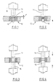
- FIG. 1 and 2 show a die 10, the bore of which forms a mold cavity 12, which is conical in cross section. With the help of such Mold cavity 12 can be formed as a compact Cutting plate, for example an indexable insert with clearance angle used becomes.
- the upper edge of the mold cavity 12 has from the upper edge of the die 12 a distance x.
- Above the die 12 is an upper punch 14 and below the die 10 a lower stamp 16 indicated.
- the stamps 14, 16 are in actuated in a suitable manner, preferably with the aid of hydraulic cylinders. This are controllable (not shown) so that they exert a desired force. Moreover they can be controlled in their speed, e.g. Legs to generate the desired force-time curve.
- the lower stamp 16 has a predetermined filling position.
- the lower stamp 16 is also set to a predetermined one Move position, as shown in Fig. 2. Here takes place a pressing process is already taking place. Subsequently, the lower stamp 16 continues proceed until a specified pressing force has been reached.
- the pressing force is like this dimensioned that the height of the to be molded for a given filling quantity Compacts (not shown) corresponds to the target height. Is the target height or target thickness has not yet been reached, it is necessary after sintering, the so shaped Edit plate to the desired size, e.g. B. to grind. Therefore it is too ensure that in the described method it is avoided that a compact is shaped with undersize.
- FIGS. 3 and 4 differs from that according to the figures 1 and 2 only in that the bore of the die is cylindrical. With the help cutting insert produced by the method therefore has no clearance angle. in the rest of the embodiment of Figures 3 and 4 with the same reference numerals like Figure 1 provided.
- Line 20 in FIG. 5 indicates the upper edge of the die.
- the thick undressed Curve 22 indicates the position profile of an upper punch and the thickly drawn Curve 24 after a lower stamp, for example the stamp 14, 16 3 and 4.
- the solid line 26 indicates the course of the position of the filling shoe.
- the lower stamp has the position a corresponding to the top edge of the die and the top stamp is clearly located above the top edge of the die.
- the filling shoe is over the die, and the lower punch moves into a first filling position b, during which one The die hole is filled with hard metal powder, as indicated at 28.
- the filling is finished at c.
- the lower stamp moves a little up to position d, which is the final fill position, d. H.
- the powder column in the die hole corresponds to the specified filling quantity. Perhaps Excess material above the upper edge 20 of the die is then removed from the filling shoe stripped. The filling shoe then moves to its starting position, and the upper stamp moves to position P2, while the lower stamp at the same time moves back a little to prevent the upper punch from powder material presses out of the die hole laterally. Then the upper stamp move to position P3, with the lower punch the one previously taken Still maintains position. Now the pressing process begins, with the position P4 of upper and lower stamps via a predetermined path that the stamp cover, can be started. With the help of suitable signposts it is possible to provide a precise path control for the stamp. Here takes place a more or less significant compression of the powder material is already taking place.
Landscapes
- Engineering & Computer Science (AREA)
- Mechanical Engineering (AREA)
- Manufacturing & Machinery (AREA)
- Powder Metallurgy (AREA)
- Punching Or Piercing (AREA)
- Coating Apparatus (AREA)
Abstract
Description
Die Erfindung bezieht sich auf ein Verfahren zur Herstellung von Preßteilen, insbesondere von Wendeschneidplatten aus Hartmetall, durch Pressen von Metallpulver und anschliessendes Sintern des Preßlings nach dem Patentanspruch 1.The invention relates to a method for producing pressed parts, in particular of carbide inserts, by pressing metal powder and subsequent sintering of the compact according to claim 1.
Es ist bekannt, Formteile aus Hartmetall, Keramik, Sintermetall oder dergleichen mit Hilfe von Pressen herzustellen. Das pulver- bzw. granuläre Material ist so bereit zu stellen, daß bei einem angewandten Preßdruck der Preßling eine homogene Struktur bekommt und sich sintern läßt. Eine übliche Formgebung ist das sogenannte Direktpressen in entsprechend ausgeführten Preßformen oder Matrizen, denen ein Ober- und Unterstempel zugeordnet sind. Entsprechend dem jeweiligen Preßdruck ergibt sich beim Preßling eine unterschiedliche Dichte. Preßlinge mit geringerer Dichte schwinden beim Sintern jedoch stärker als Preßlinge mit höherer Dichte. Durch unterschiedlich einstellbare Preßwege für Ober- und Unterstempel wird versucht, Dichteabweichungen zu minimieren. Andererseits können unterschiedliche Dichten in der Praxis durch unterschiedliche Preßkräfte entstehen, die wiederum bei gleicher Höhe der Preßlinge, z. B. durch Füllschwankungen, die bis zu einigen Prozenten gehen, hervorgerufen werden. Erschwerend bei der Herstellung von Preßlingen, z. B. für Hartmetallschneidplatten, ist das Einhalten einer vorgegebenen Gesamthöhe zwischen Plattensitz und mindestens einer Schneidkante, die einen vorgegebenen Abstand zum Plattensitz aufweist.It is known to use molded parts made of hard metal, ceramic, sintered metal or the like with the help of presses. The powder or granular material is like this ready to provide that with an applied pressing pressure of the compact a homogeneous Gets structure and can be sintered. This is a common shape so-called direct presses in appropriately designed press molds or dies, which are assigned an upper and lower stamp. According to the respective Pressing pressure results in a different density for the compact. Compacts with However, lower densities shrink more when sintered than compacts with higher ones Density. Through differently adjustable press paths for upper and lower punches an attempt is made to minimize density deviations. On the other hand, different In practice, densities arise from different pressing forces again at the same height of the compacts, e.g. B. by filling fluctuations that up go to a few percent. Difficult to manufacture von Preßlingen, z. B. for carbide inserts, compliance is one predetermined total height between insert seat and at least one cutting edge, which has a predetermined distance from the insert seat.
Aus DE 42 09 787 ist bekannt geworden, eine möglichst gleichmäßige Dichte z. B. innerhalb einer Charge zu erreichen, indem die Preßkraft gemessen und anschließend eine Korrektur über die Füllung für die nachfolgenden Preßlinge vorgenommen wird.From DE 42 09 787 it has become known that a density as uniform as possible, for. B. to achieve within a batch by measuring the pressing force and then corrected the filling for the subsequent compacts becomes.
Aus DE 197 17 217 ist ferner bekannt geworden, abhängig von der Geometrie des Preßlings und des Ausgangsmaterials während der Kompression für einen Preßstempel ein gewünschtes Kraft-Weg-Diagramm (Sollkurve) zu ermitteln und zu speichern. Mittels eines separat betätigten Abschnitts des Preßstempels oder eines getrennten Stempels wird der Druck auf das Preßmaterial während der Kompressionsphase erhöht oder verringert, sobald eine Abweichung von der Sollkurve ermittelt wird, um am Ende der Kompressionsphase eine gleiche Dichte jedes Preßlings zu erhalten. Ein derartiges Verfahren ist jedoch nur anwendbar bei Preßlingen, bei welchen die Fläche des Preßlings im mittleren Bereich unkritisch ist. Dies gilt z. B. für die Sitzfläche, bei der es ausreicht, wenn z. B. ein umlaufender Rand einen präzisen Abstand von der Schneidkante hat, während der mittlere Bereich mehr oder weniger vertieft sein kann.From DE 197 17 217 has also become known, depending on the geometry of the Compacts and the starting material during compression for a press ram a desired force-displacement diagram (target curve) to determine and to to save. By means of a separately operated section of the press ram or one Separate stamp is the pressure on the press material during the compression phase increases or decreases as soon as a deviation from the target curve is determined to have an equal density each at the end of the compression phase To obtain compacts. However, such a method can only be used for compacts, in which the area of the compact in the central area is not critical. This applies e.g. B. for the seat, where it is sufficient if, for. B. a circumferential Edge has a precise distance from the cutting edge, while the middle Area can be more or less deepened.
Der Erfindung liegt die Aufgabe zugrunde, ein Verfahren zur Herstellung von Schneidplatten aus Hartmetall durch Pressen und Sintern des Preßlings, insbesondere von Wendeschneidplatten, zu schaffen, das einfacher als das zuletzt beschriebene bekannte Verfahren ist und gleichwohl zu hervorragenden Ergebnissen führt.The invention has for its object a method for producing Carbide inserts by pressing and sintering the compact, in particular of indexable inserts, to create that easier than the last described is known method and nevertheless leads to excellent results.
Diese Aufgabe wird durch die Merkmale des Patentanspruchs 1 gelöst.This object is achieved by the features of patent claim 1.
Wie beim herkömmlichen Verfahren wird auch bei der Erfindung zunächst eine vorgegebene Menge an Metallpulver in die Matrizenbohrung eingefüllt, wobei der Unterstempel hierbei eine Einfüllposition einnimmt. Gegebenenfalls wird der Unterstempel zunächst in eine etwas tiefere Position verfahren, so daß eine geringfügige Übermenge eingefüllt wird, wonach dann der Unterstempel die endgültige Einfüllposition einnimmt und mit Hilfe des Füllschuhs der aus der Matrizenbohrung ausgestoßene Rest abgestreift wird. Anschließend werden Oberstempel und Unterstempel in eine vorgegebene erste bzw. zweite Position verfahren, wobei bereits eine gewisse Preßkraft aufgebracht werden kann. Handelt es sich um einen Preßling, der für eine Schneidplatte mit Freiwinkel gedacht ist, entspricht die Lage des Oberstempels bei der angefahrenen zweiten Position z. B. der Oberkante des Preßlings. Anschließend erfolgt ein weiteres Verstellen von Unter- und Oberstempel, wobei jedoch im Falle eines Preßlings mit Freiwinkel nur der Unterstempel verstellt wird. Bei diesem Verstellvorgang werden die Preßkräfte fortlaufend gemessen, wobei die Zustellbewegung von Unter- und Oberstempel beendet wird, wenn die Preßkraft einen vorgegebenen Wert erreicht hat. Auch bei Verstellung beider Stempel kann es ausreichen, allein die Preßkraft am Unterstempel zu messen und die Verstellbewegung zu beenden, wenn die gemessene Preßkraft den vorgegebenen Wert erreicht hat.As with the conventional method, the invention also begins with one predetermined amount of metal powder filled into the die hole, the Lower stamp assumes a filling position. If necessary, the First move the lower stamp to a slightly lower position, so that a slight Excess quantity is filled, after which the lower stamp is the final one Fills the filling position and with the help of the filling shoe from the die hole ejected rest is stripped. Then the upper stamp and move the lower punch into a predetermined first or second position, whereby a certain pressing force can already be applied. Is it one Pressed part, which is intended for a cutting plate with clearance angle, corresponds to the position the upper stamp at the approached second position z. B. the top of the Compacts. Then the lower and upper stamps are adjusted further, however, in the case of a compact with a clearance angle, only the lower stamp is adjusted. In this adjustment process, the pressing forces are continuous measured, whereby the infeed movement of the lower and upper stamps is ended, when the pressing force has reached a predetermined value. Even with adjustment both stamps, it may be sufficient to measure the pressing force on the lower stamp alone and to end the adjustment movement when the measured pressing force reaches the predetermined one Has reached value.
Der vorgegebene Wert für die Preßkraft wird durch vorangehende Versuche ermittelt. Zunächst einmal wird ermittelt, welche Verdichtung das Metallpulver erhalten soll, um anschließend dem Sinterungsprozeß ausgesetzt zu werden. Dann wird untersucht, wie groß die Füllmenge sein muß, damit beim Aufbringen einer vorgegebenen Preßkraft eine bestimmte Höhe des Preßlings reproduzierbar erreicht wird. Wird daher bei dem erfindungsgemäßen Verfahren bei einer vorgegebenen Preßkraft abgeschaltet, dann kann davon ausgegangen werden, daß die vorgegebene Höhe des Preßlings erreicht worden ist. Auf diese Weise wird auch bei gewissen Füllschwankungen eine vorgegebene Dichte des Preßlings erreicht. Da Füllschwankungen des Preßlings nicht gänzlich auszuschließen sind, wird vorzugsweise so verfahren, daß bei vorhandenen Toleranzen im Zweifel ein gewisses Übermaß vorliegt, wenn bei vorgegebenem Preßkraftwert abgeschaltet wird. Bei Übermaß wird der Preßling abgearbeitet, vorzugsweise durch Schleifen, um ihn auf die vorgegebene Höhe bzw. Dicke zu bringen.The predetermined value for the pressing force is determined by previous tests determined. First of all, it is determined what compaction the metal powder should be obtained in order to then be subjected to the sintering process. Then it is examined how large the filling quantity must be, so that when a predetermined pressing force reproducibly reaches a certain height of the compact becomes. Is therefore in the method according to the invention at a predetermined Pressing force switched off, then it can be assumed that the predetermined Height of the compact has been reached. This way, too certain filling fluctuations reached a predetermined density of the compact. There Fluctuations in the filling of the compact cannot be completely ruled out, is preferred proceed in such a way that, if there are tolerances, a certain one Excess is present if the pressure is switched off at a predetermined pressure value. At The compact is processed excessively, preferably by grinding, around it to bring to the specified height or thickness.
Nach einer Ausgestaltung der Erfindung erfolgt die Verstellung von Unterstempel und/oder Oberstempel von der ersten bzw. zweiten Position entlang einer vorgegebenen Sollkurve für die Preßkraft, wobei die Sollkurve die Abhängigkeit der Preßkraft von der Zeit wiedergibt. Auf diese Weise ist es möglich, sich den endgültigen erwünschten Preßkraftwerten auf regelnde Weise anzunähern.According to one embodiment of the invention, the lower stamp is adjusted and / or upper stamp from the first or second position along a predetermined Target curve for the pressing force, the target curve being the dependence of the pressing force reproduces from time. In this way it is possible to get the final one to approach the desired pressing force values in a regulating manner.
Während beim bekannten Verfahren zwar auch die Preßkraft gemessen wird, jedoch beim Anfahren einer vorgegebenen Position, um anschließend bei Preßkraftabweichungen die Füllmenge zu verändern, erfolgt bei der Erfindung eine unmittelbare Korrektur am Preßling.While the press force is also measured in the known method, however, when moving to a predetermined position, and then when there are deviations in the pressing force To change the filling amount takes place in the invention immediate correction on the compact.
Die Erfindung wird nachfolgend anhand von Zeichnungen näher erläutert.
- Fig. 1
- zeigt eine Presse zum Verpressen von Metallpulver nach dem erfindungsgemäßen Verfahren und von dem eigentlichen Preßvorgang.
- Fig. 2
- zeigt die Presse nach Fig. 1 während des Preßvorgangs.
- Fig. 3
- zeigt eine abgewandelte Presse zur Durchführung des erfindungsgemäßen Verfahrens oder den Preßvorgang.
- Fig. 4
- zeigt die Presse nach Fig. 3 während des Preßvorgangs.
- Fig. 5
- zeigt ein Bewegdiagramm für die Preßstempel der Presse nach den Figuren 3 und 4.
- Fig. 1
- shows a press for pressing metal powder according to the inventive method and the actual pressing process.
- Fig. 2
- shows the press of FIG. 1 during the pressing process.
- Fig. 3
- shows a modified press for performing the method according to the invention or the pressing process.
- Fig. 4
- shows the press of FIG. 3 during the pressing process.
- Fig. 5
- shows a movement diagram for the press ram of the press according to Figures 3 and 4.
In den Figuren 1 und 2 ist eine Matrize 10 dargestellt, deren Bohrung einen Formhohlraum
12 aufweist, welcher im Querschnitt konisch ist. Mit Hilfe eines derartigen
Formhohlraums 12 kann ein Preßling erzeugt werden, der als eine
Schneidplatte, beispielsweise eine Wendeschneidplatte mit Freiwinkel verwendet
wird. Die Oberkante des Formhohlraums 12 von der Oberkante der Matrize 12 hat
einen Abstand x. Oberhalb der Matrize 12 ist ein Oberstempel 14 und unterhalb
der Matrize 10 ein Unterstempel 16 angedeutet. Die Stempel 14, 16 werden in
geeigneter Weise betätigt, vorzugsweise mit Hilfe von Hydraulikzylindern. Diese
sind so steuerbar (nicht gezeigt), daß sie eine gewünschte Kraft aufbringen. Außerdem
können sie in ihrer Geschwindigkeit gesteuert werden, um z. B. eine
gewünschte Kraft-Zeit-Kurve zu erzeugen. Bei der Befüllung der Matrizenbohrung
hat der Unterstempel 16 eine vorgegebene Füllposition. Seine Position bestimmt
die Füllmenge. Vorzugsweise ist sie zu Beginn etwas niedriger als die theoretische
Füllposition für die vorgegebene Menge, damit nach dem Befüllen der Unterstempel
eine gewisse Strecke nach oben fahren kann, damit der nicht gezeigte Füllschuh
überschüssiges Material an der Matrizenoberseite abstreifen kann. Anschließend
werden Oberstempel 14 und Unterstempel 16 in die Matrizenbohrung hineingefahren,
wobei der Oberstempel 14 soweit hineinfährt, daß er an der Oberseite
des Formhohlraums 12 zu liegen kommt. Die Einfahrtiefe in die Matrizenbohrung
entspricht mithin dem Maß x. Der Unterstempel 16 wird ebenfalls auf eine vorgegebene
Position verfahren, wie sie etwa in Fig. 2 dargestellt ist. Hierbei findet
bereits ein Verpreßvorgang statt. Anschließend wird der Unterstempel 16 weiter
verfahren, bis eine vorgegebene Preßkraft erreicht worden ist. Die Preßkraft ist so
bemessen, daß bei einer vorgegebenen Füllmenge die Höhe des zu formenden
Preßlings (nicht gezeigt) der Sollhöhe entspricht. Ist die Sollhöhe oder Solldicke
noch nicht erreicht worden, ist es nach dem Sintern erforderlich, die so geformte
Platte auf das gewünschte Maß zu bearbeiten, z. B. zu schleifen. Daher ist dafür zu
sorgen, daß bei dem beschriebenen Verfahren vermieden wird, daß ein Preßling
mit Untermaß geformt wird.1 and 2 show a die 10, the bore of which forms a
Statt auf einen vorgegebenen maximalen Preßkraft-Wert zu fahren, kann auch vorgesehen
werden, den Unterstempel 16 nach einer vorgegebenen Sollkurve zu fahren,
d. h. einer Preßkraft-Kurve über der Zeit, bis der gewünschte maximale Preßkraft-Wert
erreicht worden ist. Auf diese Weise wird besser die gewünschte
Reproduzierbarkeit für die Preßkraft bzw. die Dichte des Preßlings erreicht. Ein
Ziel ist bekanntlich, eine reproduzierbare Dichte des Preßlings zu erreichen, damit
beim Sintern reproduzierbare geometrische Abmessungen erhalten werden.Instead of driving to a predetermined maximum pressing force value, provision can also be made
to drive the
Die Ausführungsform nach Fig. 3 und 4 unterscheidet sich von der nach den Figuren 1 und 2 nur dadurch, daß die Bohrung der Matrize zylindrisch ist. Die mit Hilfe des Verfahrens hergestellte Schneidplatte weist daher keinen Freiwinkel auf. Im übrigen wird die Ausführungsform der Figuren 3 und 4 mit gleichen Bezugszeichen wie Figur 1 versehen.The embodiment according to FIGS. 3 and 4 differs from that according to the figures 1 and 2 only in that the bore of the die is cylindrical. With the help cutting insert produced by the method therefore has no clearance angle. in the the rest of the embodiment of Figures 3 and 4 with the same reference numerals like Figure 1 provided.
Man erkennt aus Fig. 4, daß die Preßkraft mit beiden Stempeln 14, 16 aufgebracht
werden kann. Dies geht auch aus dem Diagramm nach Fig. 5 hervor.It can be seen from Fig. 4 that the pressing force is applied with both
Die Linie 20 in Fig. 5 deutet die Matrizenoberkante an. Die dick ausgezogene
Kurve 22 deutet den Positionsverlauf eines Oberstempels an, und die dick ausgezogene
Kurve 24 die eines Unterstempels, beispielsweise der Stempel 14, 16 nach
den Figuren 3 und 4. Die dick ausgezogene Linie 26 deutet den Positionsverlauf
des Füllschuhs an. Zu Beginn des Prozesses hat der Unterstempel die Position a
entsprechend der Oberkante der Matrize und der Oberstempel befindet sich deutlich
oberhalb der Matrizenoberkante. Der Füllschuh befindet sich über der Matrize,
und der Unterstempel verfährt in eine erste Füllposition b, während derer eine
Befüllung der Matrizenbohrung mit Hartmetallpulver erfolgt, wie bei 28 angedeutet.
Die Befüllung ist bei c beendet. Anschließend fährt der Unterstempel etwas
hoch zur Position d, welche die endgültige Füllposition darstellt, d. h. die Pulversäule
in der Matrizenbohrung entspricht der vorgegebenen Füllmenge. Eventuell
überschüssiges Material oberhalb der Matrizenoberkante 20 wird dann vom Füllschuh
abgestreift. Der Füllschuh fährt anschließend in seine Ausgangsstellung, und
der Oberstempel fährt in die Position P2, während der Unterstempel gleichzeitig
wieder etwas zurückfährt, um zu verhindern, daß der Oberstempel Pulvermaterial
seitlich aus der Matrizenbohrung herauspreßt. Anschließend wird der Oberstempel
in die Position P3 verfahren, wobei der Unterstempel die vorher eingenommene
Position noch beibehält. Nunmehr beginnt der Preßvorgang, wobei die Position P4
von Ober- und Unterstempel über einen vorgegebenen Weg, den die Stempel
zurücklegen, angefahren werden kann. Mit Hilfe von geeigneten Weggebern ist es
möglich, eine genau Wegsteuerung für die Stempel vorzusehen. Hierbei findet
bereits eine mehr oder weniger deutliche Verdichtung des Pulvermaterials statt. Ab
der Position P4 werden fortlaufend die Preßkräfte z. B. des Unterstempels gemessen,
wobei sowohl Ober- als auch Unterstempel weiter aufeinander zu gefahren
werden, wie dies in Fig. 4 gezeigt ist. Es wird angenommen, daß dann in der Position
P5 eine vorgegebene maximale Preßkraft erreicht wird. Es ist naturgemäß
auch möglich, bezüglich des Oberstempels eine vorgegebene maximale Preßkraft
einzustellen. Damit hat der Preßling eine vorgegebene Höhe bzw. Dicke bei einer
gewünschten Verdichtung des Materials. Es ist auch möglich, von der Position P4
nach P5 entlang einer vorgegebenen Sollkurve zu fahren, d. h. nach einem KraftZeit-Diagramm,
bis der gewünschte Endwert für die Preßkraft erreicht worden ist.
Zwischen P5 und P6 bleibt die Preßkraft aufrecht erhalten, wobei nach P6 der
Oberstempel leicht angehoben wird, um eine gewisse Entspannung des Preßlings
zu ermöglichen. Anschließend werden Ober- und Unterstempel gemeinsam hochgefahren,
bis der Oberstempel die Oberkante der Matrize 10 erreicht hat. Nach
einiger Zeit (Position P9) wird dann der Oberstempel nach oben gefahren und dem
Unterstempel ermöglicht, den Preßling aus der Matrizenbohrung heraus zu bewegen.
Claims (3)
Applications Claiming Priority (2)
| Application Number | Priority Date | Filing Date | Title |
|---|---|---|---|
| DE10010671A DE10010671C2 (en) | 2000-03-04 | 2000-03-04 | Process for producing pressed parts by pressing metal powder and then sintering the compact |
| DE10010671 | 2000-03-04 |
Publications (4)
| Publication Number | Publication Date |
|---|---|
| EP1129802A2 true EP1129802A2 (en) | 2001-09-05 |
| EP1129802A3 EP1129802A3 (en) | 2004-05-06 |
| EP1129802B1 EP1129802B1 (en) | 2007-03-14 |
| EP1129802B2 EP1129802B2 (en) | 2010-08-11 |
Family
ID=7633551
Family Applications (1)
| Application Number | Title | Priority Date | Filing Date |
|---|---|---|---|
| EP01104107A Expired - Lifetime EP1129802B2 (en) | 2000-03-04 | 2001-02-21 | Process for controlling the pressing force for metal powder compression |
Country Status (4)
| Country | Link |
|---|---|
| US (1) | US6562291B2 (en) |
| EP (1) | EP1129802B2 (en) |
| AT (1) | ATE356681T1 (en) |
| DE (2) | DE10010671C2 (en) |
Cited By (3)
| Publication number | Priority date | Publication date | Assignee | Title |
|---|---|---|---|---|
| EP1287975A3 (en) * | 2001-08-31 | 2004-01-28 | Fette GmbH | Process for producing molded parts in a powder press |
| EP2750151A4 (en) * | 2011-07-27 | 2015-03-11 | Sumitomo Electric Industries | BRIQUETTE IN COMPRESSED POWDER |
| DE102010015016B4 (en) * | 2009-04-24 | 2016-06-09 | Sms Group Gmbh | powder Press |
Families Citing this family (9)
| Publication number | Priority date | Publication date | Assignee | Title |
|---|---|---|---|---|
| DE10135283C2 (en) * | 2001-07-19 | 2003-09-18 | Fette Wilhelm Gmbh | Process for pressing powder material |
| DE102004008322B4 (en) * | 2004-02-20 | 2008-11-27 | Fette Gmbh | powder Press |
| EP2123435B1 (en) * | 2007-03-20 | 2016-03-09 | Tungaloy Corporation | Compression molding method for a cutting insert |
| DE102012019312A1 (en) * | 2012-10-01 | 2014-04-03 | Dorst Technologies Gmbh & Co. Kg | Method for controlling a ceramic and / or metal powder press or ceramic and / or metal powder press |
| US20160325354A1 (en) * | 2015-05-07 | 2016-11-10 | Thermal Technology, Llc | Compressive Sintering Apparatus Comprising Protected Opposing Rams |
| DE102017004803A1 (en) | 2017-05-18 | 2018-11-22 | Cosateq Gmbh | Method for operating a powder press with layer control and powder press for carrying out the method |
| DE102017119342A1 (en) | 2017-08-24 | 2019-02-28 | COSATEQ GmbH & Co. KG | Method for controlling a metal or ceramic powder press with automatic trajectory generation |
| US12528126B2 (en) | 2019-12-17 | 2026-01-20 | Kennametal Inc. | Additive manufacturing techniques and applications thereof |
| EP4079427A1 (en) * | 2021-04-22 | 2022-10-26 | GKN Sinter Metals Engineering GmbH | Method for determining a parameter of a material and pressing tool for producing a green compact |
Family Cites Families (9)
| Publication number | Priority date | Publication date | Assignee | Title |
|---|---|---|---|---|
| US4000231A (en) * | 1974-09-16 | 1976-12-28 | Hydramet American Inc. | Method for compacting powders |
| DE2825253A1 (en) † | 1978-06-08 | 1979-12-13 | Nitrochemie Gmbh | HYDRAULIC POWDER PRESS |
| SE460460B (en) † | 1983-07-01 | 1989-10-16 | Convey Teknik Ab | PROCEDURE AND DEVICE FOR REGULATED PRESSURE OF POWDER MATERIAL |
| DE3715077A1 (en) † | 1987-05-06 | 1988-12-01 | Netzsch Maschinenfabrik | Method for controlling a press |
| JP2519498B2 (en) * | 1988-01-16 | 1996-07-31 | ファナック株式会社 | Electric powder molding machine |
| DE3919821C2 (en) * | 1989-06-15 | 1994-04-07 | Mannesmann Ag | Method and device for producing dimensionally stable compacts |
| DE4209767C1 (en) * | 1992-03-23 | 1993-05-06 | Mannesmann Ag, 4000 Duesseldorf, De | |
| US5547360A (en) * | 1994-03-17 | 1996-08-20 | Tamagawa Machinery Co., Ltd. | Powder molding press |
| DE19717217C2 (en) * | 1997-04-24 | 1999-12-02 | Fette Wilhelm Gmbh | Method and device for producing compacts from hard metal, ceramic, sintered metal or the like |
-
2000
- 2000-03-04 DE DE10010671A patent/DE10010671C2/en not_active Revoked
-
2001
- 2001-02-21 AT AT01104107T patent/ATE356681T1/en active
- 2001-02-21 DE DE50112176T patent/DE50112176D1/en not_active Expired - Lifetime
- 2001-02-21 EP EP01104107A patent/EP1129802B2/en not_active Expired - Lifetime
- 2001-03-02 US US09/798,802 patent/US6562291B2/en not_active Expired - Lifetime
Cited By (4)
| Publication number | Priority date | Publication date | Assignee | Title |
|---|---|---|---|---|
| EP1287975A3 (en) * | 2001-08-31 | 2004-01-28 | Fette GmbH | Process for producing molded parts in a powder press |
| DE102010015016B4 (en) * | 2009-04-24 | 2016-06-09 | Sms Group Gmbh | powder Press |
| EP2750151A4 (en) * | 2011-07-27 | 2015-03-11 | Sumitomo Electric Industries | BRIQUETTE IN COMPRESSED POWDER |
| US9251946B2 (en) | 2011-07-27 | 2016-02-02 | Sumitomo Electric Industries, Ltd. | Compact |
Also Published As
| Publication number | Publication date |
|---|---|
| DE10010671A1 (en) | 2001-09-13 |
| US6562291B2 (en) | 2003-05-13 |
| US20010022944A1 (en) | 2001-09-20 |
| ATE356681T1 (en) | 2007-04-15 |
| EP1129802A3 (en) | 2004-05-06 |
| DE50112176D1 (en) | 2007-04-26 |
| DE10010671C2 (en) | 2002-03-14 |
| EP1129802B2 (en) | 2010-08-11 |
| EP1129802B1 (en) | 2007-03-14 |
Similar Documents
| Publication | Publication Date | Title |
|---|---|---|
| EP0873855B1 (en) | Method and apparatus for manufacturing moulded articles in hard metal, ceramic, sintered metal or similar | |
| EP1129802B1 (en) | Process for controlling the pressing force for metal powder compression | |
| DE4203401A1 (en) | METHOD AND DEVICE FOR CONTROLLING A POWDER MOLD PRESS | |
| DE4209767C1 (en) | ||
| EP3310508A1 (en) | Method and device for producing mould material moulds for the casting of metals | |
| DE68910248T2 (en) | ELECTRIC POWDER CASTING DEVICE. | |
| EP1852247A2 (en) | Press for manufacturing moulded parts from powdered material | |
| EP0679503A1 (en) | Method of making moulded articles from particulate material as well as corresponding press | |
| DE3312539C1 (en) | Apparatus for the production of boxless sand casting moulds | |
| DE102004008322B4 (en) | powder Press | |
| DE10142624A1 (en) | Method and device for pressing metal powder into a compact | |
| DE2852429A1 (en) | PROCESS IN THE MANUFACTURING OF SINTERED PARTS AND TOOLS FOR EXERCISING THE PROCESS | |
| EP1287975B1 (en) | Process for producing molded parts in a powder press | |
| DE19540850C2 (en) | Method for the two-sided pressing of molds from particle material in a mold row system | |
| DE19903417B4 (en) | Method for filling a hydraulic press with powders | |
| DE2745020B2 (en) | Method and device for the powder-metallurgical production of shaped bodies | |
| DE10256654B4 (en) | Tablet press | |
| WO2020169403A1 (en) | Method for powder pressing at least two press parts and powder pressing device | |
| DE2915966A1 (en) | Compression force measuring device for hydraulic press - uses two symmetrically-spaced pressure capsules or expansion strips | |
| EP1287977B1 (en) | Process and apparatus for minimizing the spread of maximum pressing forces in a powder press | |
| DE2357309B2 (en) | Press mold for the powder metallurgical production of contact nozzles for welding machines | |
| DE19545753B4 (en) | Regulation of frame position and pressing pressure in molding plants | |
| DE182515C (en) | ||
| DE2524412A1 (en) | Continuous bar forming press - compacts discrete quantities of powdered metal sequentially to form a continuous bar for sintering | |
| DE102004012858A1 (en) | Roller body manufacturing method for roller bearing, involves measuring weight or volume of raw blocks, and feeding blocks in to pressing tool, where blocks are shaped in tool in two stages and deformed by stamp that penetrates in to tool |
Legal Events
| Date | Code | Title | Description |
|---|---|---|---|
| PUAI | Public reference made under article 153(3) epc to a published international application that has entered the european phase |
Free format text: ORIGINAL CODE: 0009012 |
|
| 17P | Request for examination filed |
Effective date: 20010303 |
|
| AK | Designated contracting states |
Kind code of ref document: A2 Designated state(s): AT BE CH CY DE DK ES FI FR GB GR IE IT LI LU MC NL PT SE TR |
|
| AX | Request for extension of the european patent |
Free format text: AL;LT;LV;MK;RO;SI |
|
| RAP1 | Party data changed (applicant data changed or rights of an application transferred) |
Owner name: FETTE GMBH |
|
| PUAL | Search report despatched |
Free format text: ORIGINAL CODE: 0009013 |
|
| RIC1 | Information provided on ipc code assigned before grant |
Ipc: 7B 22F 3/02 A Ipc: 7B 30B 11/00 B |
|
| AK | Designated contracting states |
Kind code of ref document: A3 Designated state(s): AT BE CH CY DE DK ES FI FR GB GR IE IT LI LU MC NL PT SE TR |
|
| AX | Request for extension of the european patent |
Extension state: AL LT LV MK RO SI |
|
| AKX | Designation fees paid |
Designated state(s): AT BE CH CY DE DK ES FI FR GB GR IE IT LI LU MC NL PT SE TR |
|
| GRAP | Despatch of communication of intention to grant a patent |
Free format text: ORIGINAL CODE: EPIDOSNIGR1 |
|
| GRAS | Grant fee paid |
Free format text: ORIGINAL CODE: EPIDOSNIGR3 |
|
| GRAA | (expected) grant |
Free format text: ORIGINAL CODE: 0009210 |
|
| AK | Designated contracting states |
Kind code of ref document: B1 Designated state(s): AT BE CH CY DE DK ES FI FR GB GR IE IT LI LU MC NL PT SE TR |
|
| PG25 | Lapsed in a contracting state [announced via postgrant information from national office to epo] |
Ref country code: IE Free format text: LAPSE BECAUSE OF FAILURE TO SUBMIT A TRANSLATION OF THE DESCRIPTION OR TO PAY THE FEE WITHIN THE PRESCRIBED TIME-LIMIT Effective date: 20070314 Ref country code: FI Free format text: LAPSE BECAUSE OF FAILURE TO SUBMIT A TRANSLATION OF THE DESCRIPTION OR TO PAY THE FEE WITHIN THE PRESCRIBED TIME-LIMIT Effective date: 20070314 Ref country code: NL Free format text: LAPSE BECAUSE OF FAILURE TO SUBMIT A TRANSLATION OF THE DESCRIPTION OR TO PAY THE FEE WITHIN THE PRESCRIBED TIME-LIMIT Effective date: 20070314 |
|
| REG | Reference to a national code |
Ref country code: GB Ref legal event code: FG4D Free format text: NOT ENGLISH |
|
| REG | Reference to a national code |
Ref country code: CH Ref legal event code: NV Representative=s name: ISLER & PEDRAZZINI AG Ref country code: CH Ref legal event code: EP |
|
| REF | Corresponds to: |
Ref document number: 50112176 Country of ref document: DE Date of ref document: 20070426 Kind code of ref document: P |
|
| REG | Reference to a national code |
Ref country code: IE Ref legal event code: FG4D Free format text: LANGUAGE OF EP DOCUMENT: GERMAN |
|
| GBT | Gb: translation of ep patent filed (gb section 77(6)(a)/1977) |
Effective date: 20070502 |
|
| PG25 | Lapsed in a contracting state [announced via postgrant information from national office to epo] |
Ref country code: ES Free format text: LAPSE BECAUSE OF FAILURE TO SUBMIT A TRANSLATION OF THE DESCRIPTION OR TO PAY THE FEE WITHIN THE PRESCRIBED TIME-LIMIT Effective date: 20070625 |
|
| REG | Reference to a national code |
Ref country code: SE Ref legal event code: TRGR |
|
| PG25 | Lapsed in a contracting state [announced via postgrant information from national office to epo] |
Ref country code: PT Free format text: LAPSE BECAUSE OF FAILURE TO SUBMIT A TRANSLATION OF THE DESCRIPTION OR TO PAY THE FEE WITHIN THE PRESCRIBED TIME-LIMIT Effective date: 20070814 |
|
| NLV1 | Nl: lapsed or annulled due to failure to fulfill the requirements of art. 29p and 29m of the patents act | ||
| ET | Fr: translation filed | ||
| REG | Reference to a national code |
Ref country code: CH Ref legal event code: PCAR Free format text: ISLER & PEDRAZZINI AG;POSTFACH 1772;8027 ZUERICH (CH) |
|
| REG | Reference to a national code |
Ref country code: IE Ref legal event code: FD4D |
|
| PLBI | Opposition filed |
Free format text: ORIGINAL CODE: 0009260 |
|
| PLAX | Notice of opposition and request to file observation + time limit sent |
Free format text: ORIGINAL CODE: EPIDOSNOBS2 |
|
| 26 | Opposition filed |
Opponent name: OSTERWALDER AG Effective date: 20071214 Opponent name: KORSCH AG Effective date: 20071213 |
|
| PG25 | Lapsed in a contracting state [announced via postgrant information from national office to epo] |
Ref country code: DK Free format text: LAPSE BECAUSE OF FAILURE TO SUBMIT A TRANSLATION OF THE DESCRIPTION OR TO PAY THE FEE WITHIN THE PRESCRIBED TIME-LIMIT Effective date: 20070314 |
|
| PG25 | Lapsed in a contracting state [announced via postgrant information from national office to epo] |
Ref country code: GR Free format text: LAPSE BECAUSE OF FAILURE TO SUBMIT A TRANSLATION OF THE DESCRIPTION OR TO PAY THE FEE WITHIN THE PRESCRIBED TIME-LIMIT Effective date: 20070615 |
|
| PLAF | Information modified related to communication of a notice of opposition and request to file observations + time limit |
Free format text: ORIGINAL CODE: EPIDOSCOBS2 |
|
| PLAB | Opposition data, opponent's data or that of the opponent's representative modified |
Free format text: ORIGINAL CODE: 0009299OPPO |
|
| PLBB | Reply of patent proprietor to notice(s) of opposition received |
Free format text: ORIGINAL CODE: EPIDOSNOBS3 |
|
| BERE | Be: lapsed |
Owner name: FETTE G.M.B.H. Effective date: 20080228 |
|
| PG25 | Lapsed in a contracting state [announced via postgrant information from national office to epo] |
Ref country code: MC Free format text: LAPSE BECAUSE OF NON-PAYMENT OF DUE FEES Effective date: 20080228 |
|
| PG25 | Lapsed in a contracting state [announced via postgrant information from national office to epo] |
Ref country code: BE Free format text: LAPSE BECAUSE OF NON-PAYMENT OF DUE FEES Effective date: 20080228 |
|
| PG25 | Lapsed in a contracting state [announced via postgrant information from national office to epo] |
Ref country code: CY Free format text: LAPSE BECAUSE OF FAILURE TO SUBMIT A TRANSLATION OF THE DESCRIPTION OR TO PAY THE FEE WITHIN THE PRESCRIBED TIME-LIMIT Effective date: 20070314 |
|
| PG25 | Lapsed in a contracting state [announced via postgrant information from national office to epo] |
Ref country code: LU Free format text: LAPSE BECAUSE OF NON-PAYMENT OF DUE FEES Effective date: 20080221 |
|
| PUAH | Patent maintained in amended form |
Free format text: ORIGINAL CODE: 0009272 |
|
| STAA | Information on the status of an ep patent application or granted ep patent |
Free format text: STATUS: PATENT MAINTAINED AS AMENDED |
|
| 27A | Patent maintained in amended form |
Effective date: 20100811 |
|
| AK | Designated contracting states |
Kind code of ref document: B2 Designated state(s): AT BE CH CY DE DK ES FI FR GB GR IE IT LI LU MC NL PT SE TR |
|
| REG | Reference to a national code |
Ref country code: CH Ref legal event code: AEN Free format text: AUFRECHTERHALTUNG DES PATENTES IN GEAENDERTER FORM |
|
| PG25 | Lapsed in a contracting state [announced via postgrant information from national office to epo] |
Ref country code: TR Free format text: LAPSE BECAUSE OF FAILURE TO SUBMIT A TRANSLATION OF THE DESCRIPTION OR TO PAY THE FEE WITHIN THE PRESCRIBED TIME-LIMIT Effective date: 20070314 |
|
| REG | Reference to a national code |
Ref country code: SE Ref legal event code: RPEO |
|
| REG | Reference to a national code |
Ref country code: DE Ref legal event code: R082 Ref document number: 50112176 Country of ref document: DE Representative=s name: HAUCK PATENT- UND RECHTSANWAELTE, DE Effective date: 20110621 Ref country code: DE Ref legal event code: R081 Ref document number: 50112176 Country of ref document: DE Owner name: FETTE COMPACTING GMBH, DE Free format text: FORMER OWNER: FETTE GMBH, 21493 SCHWARZENBEK, DE Effective date: 20110621 Ref country code: DE Ref legal event code: R082 Ref document number: 50112176 Country of ref document: DE Representative=s name: HAUCK PATENTANWALTSPARTNERSCHAFT MBB, DE Effective date: 20110621 |
|
| REG | Reference to a national code |
Ref country code: FR Ref legal event code: PLFP Year of fee payment: 15 |
|
| PGFP | Annual fee paid to national office [announced via postgrant information from national office to epo] |
Ref country code: CH Payment date: 20150223 Year of fee payment: 15 Ref country code: IT Payment date: 20150224 Year of fee payment: 15 |
|
| PGFP | Annual fee paid to national office [announced via postgrant information from national office to epo] |
Ref country code: SE Payment date: 20150223 Year of fee payment: 15 Ref country code: AT Payment date: 20150218 Year of fee payment: 15 Ref country code: FR Payment date: 20150217 Year of fee payment: 15 Ref country code: GB Payment date: 20150223 Year of fee payment: 15 |
|
| PGFP | Annual fee paid to national office [announced via postgrant information from national office to epo] |
Ref country code: DE Payment date: 20150409 Year of fee payment: 15 |
|
| REG | Reference to a national code |
Ref country code: DE Ref legal event code: R119 Ref document number: 50112176 Country of ref document: DE |
|
| REG | Reference to a national code |
Ref country code: CH Ref legal event code: PL |
|
| REG | Reference to a national code |
Ref country code: SE Ref legal event code: EUG |
|
| REG | Reference to a national code |
Ref country code: AT Ref legal event code: MM01 Ref document number: 356681 Country of ref document: AT Kind code of ref document: T Effective date: 20160221 |
|
| GBPC | Gb: european patent ceased through non-payment of renewal fee |
Effective date: 20160221 |
|
| PG25 | Lapsed in a contracting state [announced via postgrant information from national office to epo] |
Ref country code: LI Free format text: LAPSE BECAUSE OF NON-PAYMENT OF DUE FEES Effective date: 20160229 Ref country code: CH Free format text: LAPSE BECAUSE OF NON-PAYMENT OF DUE FEES Effective date: 20160229 |
|
| REG | Reference to a national code |
Ref country code: FR Ref legal event code: ST Effective date: 20161028 |
|
| PG25 | Lapsed in a contracting state [announced via postgrant information from national office to epo] |
Ref country code: AT Free format text: LAPSE BECAUSE OF NON-PAYMENT OF DUE FEES Effective date: 20160221 Ref country code: SE Free format text: LAPSE BECAUSE OF NON-PAYMENT OF DUE FEES Effective date: 20160222 |
|
| PG25 | Lapsed in a contracting state [announced via postgrant information from national office to epo] |
Ref country code: IT Free format text: LAPSE BECAUSE OF NON-PAYMENT OF DUE FEES Effective date: 20160221 |
|
| PG25 | Lapsed in a contracting state [announced via postgrant information from national office to epo] |
Ref country code: DE Free format text: LAPSE BECAUSE OF NON-PAYMENT OF DUE FEES Effective date: 20160901 Ref country code: GB Free format text: LAPSE BECAUSE OF NON-PAYMENT OF DUE FEES Effective date: 20160221 Ref country code: FR Free format text: LAPSE BECAUSE OF NON-PAYMENT OF DUE FEES Effective date: 20160229 |