EP1129809A2 - Antriebseinheit für die Druckwelle einer Schweissvorrichtung - Google Patents
Antriebseinheit für die Druckwelle einer Schweissvorrichtung Download PDFInfo
- Publication number
- EP1129809A2 EP1129809A2 EP01104917A EP01104917A EP1129809A2 EP 1129809 A2 EP1129809 A2 EP 1129809A2 EP 01104917 A EP01104917 A EP 01104917A EP 01104917 A EP01104917 A EP 01104917A EP 1129809 A2 EP1129809 A2 EP 1129809A2
- Authority
- EP
- European Patent Office
- Prior art keywords
- pressure application
- application shaft
- driving unit
- housing
- shaft
- Prior art date
- Legal status (The legal status is an assumption and is not a legal conclusion. Google has not performed a legal analysis and makes no representation as to the accuracy of the status listed.)
- Granted
Links
- 238000003466 welding Methods 0.000 title claims abstract description 28
- 238000005096 rolling process Methods 0.000 claims abstract description 27
- 230000035515 penetration Effects 0.000 claims description 12
- 238000003754 machining Methods 0.000 claims description 10
- 229910000838 Al alloy Inorganic materials 0.000 claims description 5
- 238000001125 extrusion Methods 0.000 claims description 5
- 238000005452 bending Methods 0.000 description 2
- 238000004519 manufacturing process Methods 0.000 description 2
- 239000000463 material Substances 0.000 description 2
- 239000000428 dust Substances 0.000 description 1
- 238000000034 method Methods 0.000 description 1
- 238000009877 rendering Methods 0.000 description 1
- 210000000707 wrist Anatomy 0.000 description 1
Images

Classifications
-
- B—PERFORMING OPERATIONS; TRANSPORTING
- B23—MACHINE TOOLS; METAL-WORKING NOT OTHERWISE PROVIDED FOR
- B23K—SOLDERING OR UNSOLDERING; WELDING; CLADDING OR PLATING BY SOLDERING OR WELDING; CUTTING BY APPLYING HEAT LOCALLY, e.g. FLAME CUTTING; WORKING BY LASER BEAM
- B23K20/00—Non-electric welding by applying impact or other pressure, with or without the application of heat, e.g. cladding or plating
-
- B—PERFORMING OPERATIONS; TRANSPORTING
- B23—MACHINE TOOLS; METAL-WORKING NOT OTHERWISE PROVIDED FOR
- B23K—SOLDERING OR UNSOLDERING; WELDING; CLADDING OR PLATING BY SOLDERING OR WELDING; CUTTING BY APPLYING HEAT LOCALLY, e.g. FLAME CUTTING; WORKING BY LASER BEAM
- B23K11/00—Resistance welding; Severing by resistance heating
- B23K11/30—Features relating to electrodes
- B23K11/31—Electrode holders and actuating devices therefor
- B23K11/314—Spot welding guns, e.g. mounted on robots
- B23K11/315—Spot welding guns, e.g. mounted on robots with one electrode moving on a linear path
-
- B—PERFORMING OPERATIONS; TRANSPORTING
- B23—MACHINE TOOLS; METAL-WORKING NOT OTHERWISE PROVIDED FOR
- B23K—SOLDERING OR UNSOLDERING; WELDING; CLADDING OR PLATING BY SOLDERING OR WELDING; CUTTING BY APPLYING HEAT LOCALLY, e.g. FLAME CUTTING; WORKING BY LASER BEAM
- B23K11/00—Resistance welding; Severing by resistance heating
- B23K11/30—Features relating to electrodes
- B23K11/31—Electrode holders and actuating devices therefor
- B23K11/311—Electrode holders and actuating devices therefor the actuating device comprising an electric motor
-
- B—PERFORMING OPERATIONS; TRANSPORTING
- B23—MACHINE TOOLS; METAL-WORKING NOT OTHERWISE PROVIDED FOR
- B23K—SOLDERING OR UNSOLDERING; WELDING; CLADDING OR PLATING BY SOLDERING OR WELDING; CUTTING BY APPLYING HEAT LOCALLY, e.g. FLAME CUTTING; WORKING BY LASER BEAM
- B23K11/00—Resistance welding; Severing by resistance heating
- B23K11/30—Features relating to electrodes
- B23K11/31—Electrode holders and actuating devices therefor
- B23K11/314—Spot welding guns, e.g. mounted on robots
-
- F—MECHANICAL ENGINEERING; LIGHTING; HEATING; WEAPONS; BLASTING
- F16—ENGINEERING ELEMENTS AND UNITS; GENERAL MEASURES FOR PRODUCING AND MAINTAINING EFFECTIVE FUNCTIONING OF MACHINES OR INSTALLATIONS; THERMAL INSULATION IN GENERAL
- F16H—GEARING
- F16H25/00—Gearings comprising primarily only cams, cam-followers and screw-and-nut mechanisms
- F16H25/18—Gearings comprising primarily only cams, cam-followers and screw-and-nut mechanisms for conveying or interconverting oscillating or reciprocating motions
- F16H25/20—Screw mechanisms
- F16H25/22—Screw mechanisms with balls, rollers, or similar members between the co-operating parts; Elements essential to the use of such members
-
- Y—GENERAL TAGGING OF NEW TECHNOLOGICAL DEVELOPMENTS; GENERAL TAGGING OF CROSS-SECTIONAL TECHNOLOGIES SPANNING OVER SEVERAL SECTIONS OF THE IPC; TECHNICAL SUBJECTS COVERED BY FORMER USPC CROSS-REFERENCE ART COLLECTIONS [XRACs] AND DIGESTS
- Y10—TECHNICAL SUBJECTS COVERED BY FORMER USPC
- Y10T—TECHNICAL SUBJECTS COVERED BY FORMER US CLASSIFICATION
- Y10T74/00—Machine element or mechanism
- Y10T74/18—Mechanical movements
- Y10T74/18568—Reciprocating or oscillating to or from alternating rotary
- Y10T74/18576—Reciprocating or oscillating to or from alternating rotary including screw and nut
- Y10T74/18656—Carriage surrounded, guided, and primarily supported by member other than screw [e.g., linear guide, etc.]
Definitions
- the invention relates to a driving unit for pressure application shaft to be driven by a motor in a welding apparatus, wherein a ball screw mechanism for converting rotation of an output shaft of the motor into a reciprocating motion of the pressure application shaft is housed in a housing and a direct acting type rolling guide mechanism is provided between the pressure application shaft for holding the ball screw mechanism and the housing.
- a driving unit for pressure application shaft in a welding gun connected to a wrist of a robot has been conventionally disclosed in, for example, Japanese Patent Laid-Open Publication No. 9-47881, wherein a ball screw mechanism for converting rotation of an output shaft of the motor into a reciprocating motion of the pressure application shaft is housed in a housing and a direct acting type rolling guide mechanism provided between a pressure application shaft member and the housing.
- the pressure application shaft for holding the ball screw mechanism is arranged inside a cylinder constituting the housing, a ball box constituting the direct acting type rolling bearing is fixed to the rear end of the pressure application shaft, and a rail provided with a guide groove at the face confronting the ball box is fixed to the inner wall of the cylinder, whereby these components are assembled inside the cylinder, thereby completing the driving unit for pressure application shaft.
- the driving unit for pressure application shaft comprising the rail, the bearing, the ball screw mechanism, and so forth are assembled in the housing, and an assembling process thereof is troublesome, and hence it is difficult to manufacture a product having high accuracy, arising a problem of high manufacturing cost.
- the invention has been developed to solve the foregoing problem of the prior art, and has an object to provide a driving unit for pressure application shaft in a welding apparatus having components constituting the driving unit for pressure application shaft are integrally assembled with one another, wherein the driving unit for pressure application shaft is integrally fixed to a housing body, thereby easily obtaining the driving unit for pressure application shaft having high accuracy so that the driving unit for pressure application shaft in a welding apparatus with high accuracy at low cost can be obtained.
- the driving unit for pressure application shaft in a welding apparatus to be driven by a motor including a housing 8 for housing therein a ball screw mechanism 11 for converting rotation of an output shaft of a motor 1 into reciprocating motion of a pressure application shaft 7, and a direct acting type rolling guide mechanism 12, 13 provided between a pressure application shaft member and the housing 8, wherein the housing 8 comprises a housing body 9 which is opened at one side in a substantially U-shape in cross section, and a plate 10 for covering the opened portion, and wherein pressure application mechanism members comprise the ball screw mechanism 11, the pressure application shaft member, the direct acting type rolling bearing 12 which is fixed to the pressure application shaft member, and a rail 13 combined with the direct acting type rolling bearing 12, and wherein the pressure application mechanism members are fixed to the housing body 9, and the plate 10 is fixed to the opened portion of the housing body 9.
- the driving unit for pressure application shaft in a welding apparatus is characterized in that a front end of the housing 8 is covered with a front wall 21, and a penetration hole 22 through which the pressure application shaft 7 is inserted is formed on the front wall 21, and no bearing is provided in the penetration hole 22.
- the driving unit for pressure application shaft in a welding apparatus is characterized in that a rear end of a fixed arm is fixed to the U-shaped housing body 9.
- the driving unit for pressure application shaft in a welding apparatus is characterized in that the U-shaped housing body 9 is formed by an extrusion molded member made of aluminum alloy.
- the driving unit for pressure application shaft in a welding apparatus is characterized in that a machining portion for manually rotating a ball screw shaft is formed at the rear end of the ball screw shaft of the ball screw mechanism 11.
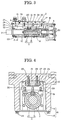
- a driving unit for pressure application shaft in a welding apparatus of the invention is described with reference to Figs. 1 to 4.
- a motor for driving a driving unit 2 for pressure application shaft (hereinafter simply referred to as driving unit 2) in a welding apparatus, and a toothed belt 6 is extended between a pulley 4 provided on an output shaft 3 of the motor 1 and a pulley 5 provided on the driving unit 2.
- an electrode for applying a pressure to weld a workpiece in the case of a C-type welding gun
- a connection member (not shown) connected to a gun arm in the case of an X-type welding gun and a work placing table (not shown) in the case of a welding jig.
- the housing 8 Depicted by 8 is a housing for the driving unit 2, and the housing 8 comprises a housing body 9 which is opened at one side in a substantially U-shape in cross section, and a plate 10 for covering the opened portion.
- Pressure application mechanism members comprising the pressure application shaft 7 incorporating the ball screw mechanism 11 therein, a direct acting type rolling bearing 12 fixed to the pressure application shaft 7 and a rail 13 combined with the direct acting type rolling bearing 12 are arranged in the housing 8.
- the housing body 9 is formed by an extrusion molded member made of aluminum alloy.
- the ball screw mechanism 11 comprises a screw shaft 14 and a ball nut 15 engaging with the screw shaft 14, wherein the screw shaft 14 penetrates the ball nut 15, and it is supported by a bearing 16 at the rear portion, and the pulley 5 by which a driving force of the motor 1 is transmitted via the toothed belt 6 is fixed to the rear end of the screw shaft 14.
- a machining portion 30 such as a machining hole or machining projection for manually rotating the screw shaft 14 at the time when the motor 1 is in trouble is formed on the rearmost portion of the screw shaft 14.
- the ball nut 15 is fixed to the angular portion of the pressure application shaft 7 at the rear end thereof by a plurality of bolts 18, 18...at a square flange 17 provided at the rear portion of the ball nut 15.
- the pressure application shaft 7 has projection pieces 19, 19 for holding bolts at the rear end side thereof, and the pressure application shaft 7 and the direct acting type rolling bearing 12 are integrated with each other by bolts 20, 20...which are inserted into the projection pieces 19, 19.
- the pressure application shaft 7 penetrates a penetration hole 22 formed in a front wall 21 for covering the front end of the housing 8 and extended outward the housing 8, and connected to, for example, one gun arm of an X-type electric gun so as to apply a pressure to electrodes attached to the tip ends of the gun arm.
- a bearing is not provided in the penetration hole 22 and the pressure application shaft 7 is inserted into the penetration hole 22 with a gap therebetween, and a scraper 23 and a dust seal 24 are engaged in the gap, and hence the penetration hole 22 is structured as a so-called bearingless one.
- the pressure application shaft 7 forms a movable arm, and the tip end of the fixed arm is attached to the housing body 9.
- the direct acting type rolling bearing 12 is formed substantially in a U-shape, and the rail 13 is arranged at the opened portion side.
- Grooves 26 for accommodating balls 25, 25 are formed on the portion confronting the rail 13 of the direct acting type rolling bearing 12 at the upper and lower surfaces wherein the grooves 26 cooperate together with projections 27 formed on the rail 13.
- the rail 13 is assembled with the direct acting type rolling bearing 12 and fixed to the housing body 9 by bolts 28, 28, so as to function as a stopper for stopping the rotation of the pressure application shaft 7 and as a guide for the reciprocating motion thereof.
- Depicted by 29, 29, are bolts for fixing the plate 10 to the housing body 9.
- the motor 1 In order to reciprocate the pressure application shaft 7 serving as a movable arm of the C-type welding gun, the motor 1 is rotated to rotate the pulley 5 by way of the toothed belt 6 so that the screw shaft 14 is rotated and the ball nut 15 is to be rotated by the rotation of the screw shaft 14.
- the rotating force of the screw shaft 14 is restrained by the direct acting type rolling bearing 12, and it is converted into a reciprocating motion of the ball nut 15, and hence the pressure application shaft 7 incorporating the ball nut 15 at its rear portion performs forward or rearward motion.
- the housing 8 comprises a housing body 9 which is opened at one side in a substantially U-shape in cross section, and a plate 10 for covering the opened portion, and pressure application mechanism members comprised of the pressure application shaft 7 incorporating ball screw mechanism 11 at the rear portion, the pressure application shaft member, the direct acting type rolling bearing 12 which is fixed to the ball screw mechanism 11, and a rail 13 combined with the direct acting type rolling bearing 12 are assembled integrally with one another, and the pressure application mechanism are fixed to the housing body 9, and particularly, the rail 13 and the direct acting type rolling bearing 12 requiring assembly thereof with high precision can be assembled in advance outside the housing 8 so that accurate assembly can be made with ease. Further, since the screw shaft 14,the ball nut 15, the pressure application shaft 7, the direct acting type rolling bearing 12, the rail 13 and so forth can be assembled with one another outside the housing 8, the assembly thereof can be made with very ease.
- the rail 13 can be directly fixed to the housing body 9 without intervening the plate 10, a plate which costs high is not required. Further, since all the parts relating to the accuracy of a central axis in the longitudinal direction through which the pressure application shaft 7 moves needed for a smooth and straight motion of the pressure application shaft 7 are assembled with the housing body 9, and the assembling accuracy is automatically attained by taking care of a mechanical machining accuracy of the housing body 9, and hence the accuracy of the passing core can be made with very ease.
- the front end of the housing 8 is covered with the front wall 21, and the penetration hole 22 through which the pressure application shaft 7 is inserted is formed in the front wall 21 while the penetration hole 22 is formed in a bearingless one, there does not occur inconvenience such as biting of a bearing, even if a sputter is attached to the surface of the pressure application shaft 7. Further, if a bending moment caused by the application of eccentric pressure (caused by eccentric alignment between the axis of electrodes or chip of the welding gun and the axis of the pressure application shaft 7) is applied to the pressure application shaft 7, the direct acting type rolling bearing 12 alone can receive a load so that the influence upon welding can be controlled to the minimum.
- the entire length of the housing becomes short so that the electric gun can be accommodated in compact.
- the housing body 9 is formed by an extrusion molded member made of aluminum alloy, it can be formed with ease so that a material cost and a mechanical machining cost can be sharply reduced.
- the screw shaft 14 is rotated utilizing the machining portion 30 when the motor is in trouble or the like so that the pressure application shaft 7 is returned to a desired position.
- the housing comprises a housing body which is opened at one side in a substantially U-shape in cross section, and a plate for covering the opened portion
- pressure application mechanism members comprise the ball screw mechanism, the pressure application shaft member, the direct acting type rolling bearing which is fixed to the ball screw mechanism, and a rail combined with the direct acting type rolling bearing, and wherein the pressure application mechanism members are fixed to the housing body, and the plate is fixed to the opened portion of the housing body, thereby obtaining the driving unit for pressure application shaft in a welding apparatus capable of assembling the high precious driving unit for pressure application shaft with ease and of being manufactured at low cost.
- a front end of the housing is covered with a front wall, and a penetration hole through which the pressure application shaft is inserted is formed on the front wall, and no bearing is provided in the penetration hole, there does not occur inconvenience such as biting of a bearing. Further, if a bending moment caused by the application of eccentric pressure to the pressure application shaft, the direct acting type rolling bearing alone can receive a load so that the influence upon welding can be controlled to the minimum.
- the U-shaped housing body is formed by an extrusion molded member made of aluminum alloy, it can be formed with ease, thereby providing the driving unit for pressure application shaft in a welding apparatus which can be manufactured at low cost.
- the pressure application shaft is returned to a desired position in response to a case where the motor is in trouble or the like.
Landscapes
- Engineering & Computer Science (AREA)
- Mechanical Engineering (AREA)
- Robotics (AREA)
- Resistance Welding (AREA)
- Transmission Devices (AREA)
- Pressure Welding/Diffusion-Bonding (AREA)
- Lining Or Joining Of Plastics Or The Like (AREA)
Applications Claiming Priority (2)
| Application Number | Priority Date | Filing Date | Title |
|---|---|---|---|
| JP2000055143 | 2000-03-01 | ||
| JP2000055143A JP4412798B2 (ja) | 2000-03-01 | 2000-03-01 | 溶接装置における加圧軸駆動装置 |
Publications (3)
| Publication Number | Publication Date |
|---|---|
| EP1129809A2 true EP1129809A2 (de) | 2001-09-05 |
| EP1129809A3 EP1129809A3 (de) | 2002-09-18 |
| EP1129809B1 EP1129809B1 (de) | 2006-12-20 |
Family
ID=18576310
Family Applications (1)
| Application Number | Title | Priority Date | Filing Date |
|---|---|---|---|
| EP01104917A Expired - Lifetime EP1129809B1 (de) | 2000-03-01 | 2001-02-28 | Antriebseinheit für die Druckwelle einer Schweissvorrichtung |
Country Status (7)
| Country | Link |
|---|---|
| US (2) | US20010019038A1 (de) |
| EP (1) | EP1129809B1 (de) |
| JP (1) | JP4412798B2 (de) |
| KR (1) | KR100631261B1 (de) |
| AT (1) | ATE348681T1 (de) |
| DE (1) | DE60125262T2 (de) |
| ES (1) | ES2273757T3 (de) |
Cited By (3)
| Publication number | Priority date | Publication date | Assignee | Title |
|---|---|---|---|---|
| EP1820594A3 (de) * | 2006-02-17 | 2011-08-10 | Dengensha Manufacturing Company Limited | Widerstandspunktschweisser |
| CN104033556A (zh) * | 2014-06-06 | 2014-09-10 | 嘉善铨盛自动化机械有限公司 | 滚珠丝杠锁紧定位装置 |
| CN106960923A (zh) * | 2017-04-19 | 2017-07-18 | 朱剑 | 一种动力电池安全盖帽超声波焊接生产测试线 |
Families Citing this family (11)
| Publication number | Priority date | Publication date | Assignee | Title |
|---|---|---|---|---|
| WO2005067674A2 (en) * | 2004-01-08 | 2005-07-28 | Tol-O-Matic, Inc. | Electric actuator |
| DE102005040441B4 (de) * | 2005-08-26 | 2009-01-15 | Airbus Deutschland Gmbh | Linearstellorgan zur Fernbetätigung von verstellbaren Komponenten an Windkanalmodellen |
| US8196484B2 (en) * | 2008-04-18 | 2012-06-12 | Tol-O-Matic, Inc. | Electric actuator |
| DE102008054103A1 (de) * | 2008-10-31 | 2010-05-06 | Friatec Aktiengesellschaft | Bauelement für Anwendungen im Brauch- und/oder Abwasserbereich und Absperrarmatur mit einem derartigen Bauelement |
| JP5399728B2 (ja) * | 2009-02-04 | 2014-01-29 | 株式会社電元社製作所 | 抵抗溶接機用直動アクチュエータ |
| US9431868B2 (en) * | 2010-01-19 | 2016-08-30 | Tolomatic, Inc. | Manual override device for an electric actuator and method for use |
| US8701513B2 (en) | 2010-07-14 | 2014-04-22 | Tol-O-Matic, Inc. | Screw driven linear actuator and housing assembly |
| DE102017112448A1 (de) * | 2017-06-06 | 2018-12-06 | Arnold & Shinjo Gmbh & Co. Kg | Vorrichtung und Verfahren zur Herstellung eines Bauteilverbunds sowie Kraftfahrzeug |
| US11925996B2 (en) | 2018-11-27 | 2024-03-12 | Tolomatic, Inc. | Integrated guide linear actuator system |
| US11754157B2 (en) | 2020-05-20 | 2023-09-12 | Tolomatic, Inc. | Integrated motor linear actuator |
| CN119635314B (zh) * | 2024-12-19 | 2025-09-23 | 江苏金博容爵机械有限公司 | 一种驱动桥焊接生产线 |
Family Cites Families (20)
| Publication number | Priority date | Publication date | Assignee | Title |
|---|---|---|---|---|
| US4147073A (en) | 1977-07-01 | 1979-04-03 | Carl Mercier | Garage door opener |
| US4271733A (en) | 1978-09-08 | 1981-06-09 | United Kingdom Atomic Energy Authority | Rotary tools |
| DE3507497C1 (de) | 1985-03-02 | 1986-07-31 | PROMA Produkt- und Marketing-Gesellschaft mbH, 7310 Plochingen | Mechanische Linearantriebseinheit |
| DE3824867C1 (en) * | 1988-07-21 | 1989-10-05 | Josef 7312 Kirchheim De Pradler | Linear drive unit having a multi-element housing |
| US5170675A (en) | 1990-07-30 | 1992-12-15 | Nsk Ltd. | Linear movement table apparatus |
| JPH06170676A (ja) | 1992-12-04 | 1994-06-21 | Toshiba Mach Co Ltd | 工作機械の軸回転駆動装置 |
| JP2700621B2 (ja) | 1995-02-20 | 1998-01-21 | セイコー精機株式会社 | ロボット |
| JP3695784B2 (ja) | 1995-03-08 | 2005-09-14 | Smc株式会社 | 電動アクチュエータ |
| JPH0947881A (ja) | 1995-08-03 | 1997-02-18 | Obara Kk | C型溶接ガンの制御装置 |
| JP3705641B2 (ja) | 1996-01-19 | 2005-10-12 | Smc株式会社 | アクチュエータ |
| JP2942496B2 (ja) * | 1996-03-07 | 1999-08-30 | 株式会社椿本チエイン | ねじ式直線作動機の廻り止め機構 |
| JP3575581B2 (ja) * | 1997-05-27 | 2004-10-13 | 株式会社電元社製作所 | 電動式ガン |
| JP3899617B2 (ja) | 1997-10-20 | 2007-03-28 | Smc株式会社 | アクチュエータ |
| JP3419674B2 (ja) * | 1998-01-09 | 2003-06-23 | Obara株式会社 | 電動ガンの加圧軸駆動装置 |
| JPH11218204A (ja) | 1998-01-29 | 1999-08-10 | Nippon Seiko Kk | 一軸テーブル送り装置 |
| US6337456B1 (en) | 1998-12-16 | 2002-01-08 | Dengensha Manufacturing Company Limited | Welding machine and method for assembling same |
| US6145395A (en) | 1999-01-19 | 2000-11-14 | E-Drive Design, Inc. | Side load compensated linear actuator |
| JP3456696B2 (ja) | 1999-06-18 | 2003-10-14 | Obara株式会社 | 電動溶接ガンの加圧駆動装置 |
| US6223971B1 (en) | 1999-11-24 | 2001-05-01 | Obara Corporation | Driving unit of a welding equipment |
| JP2001170775A (ja) | 1999-12-13 | 2001-06-26 | Obara Corp | 溶接装置の駆動装置 |
-
2000
- 2000-03-01 JP JP2000055143A patent/JP4412798B2/ja not_active Expired - Lifetime
- 2000-04-25 KR KR1020000021907A patent/KR100631261B1/ko not_active Expired - Lifetime
-
2001
- 2001-02-28 ES ES01104917T patent/ES2273757T3/es not_active Expired - Lifetime
- 2001-02-28 EP EP01104917A patent/EP1129809B1/de not_active Expired - Lifetime
- 2001-02-28 US US09/796,018 patent/US20010019038A1/en not_active Abandoned
- 2001-02-28 AT AT01104917T patent/ATE348681T1/de not_active IP Right Cessation
- 2001-02-28 DE DE60125262T patent/DE60125262T2/de not_active Expired - Lifetime
-
2003
- 2003-05-13 US US10/436,735 patent/US6718837B2/en not_active Expired - Fee Related
Cited By (5)
| Publication number | Priority date | Publication date | Assignee | Title |
|---|---|---|---|---|
| EP1820594A3 (de) * | 2006-02-17 | 2011-08-10 | Dengensha Manufacturing Company Limited | Widerstandspunktschweisser |
| EP2452772A1 (de) * | 2006-02-17 | 2012-05-16 | Dengensha Manufacturing Company Limited | Widerstandspunktschweissgerät |
| US8754347B2 (en) | 2006-02-17 | 2014-06-17 | Dengensha Manufacturing Company Limited | Resistance spot welder |
| CN104033556A (zh) * | 2014-06-06 | 2014-09-10 | 嘉善铨盛自动化机械有限公司 | 滚珠丝杠锁紧定位装置 |
| CN106960923A (zh) * | 2017-04-19 | 2017-07-18 | 朱剑 | 一种动力电池安全盖帽超声波焊接生产测试线 |
Also Published As
| Publication number | Publication date |
|---|---|
| JP4412798B2 (ja) | 2010-02-10 |
| EP1129809B1 (de) | 2006-12-20 |
| EP1129809A3 (de) | 2002-09-18 |
| DE60125262D1 (de) | 2007-02-01 |
| DE60125262T2 (de) | 2007-07-05 |
| KR20010087087A (ko) | 2001-09-15 |
| JP2001246477A (ja) | 2001-09-11 |
| KR100631261B1 (ko) | 2006-10-02 |
| ATE348681T1 (de) | 2007-01-15 |
| US20010019038A1 (en) | 2001-09-06 |
| US6718837B2 (en) | 2004-04-13 |
| US20030196502A1 (en) | 2003-10-23 |
| ES2273757T3 (es) | 2007-05-16 |
Similar Documents
| Publication | Publication Date | Title |
|---|---|---|
| EP1129809B1 (de) | Antriebseinheit für die Druckwelle einer Schweissvorrichtung | |
| US20040113342A1 (en) | Power-driven toggle-lever clamping device | |
| JP2001525520A (ja) | 動力伝達経路における軸線方向の遊びをなくした車両器具を駆動するためのギア付きモータユニット | |
| US7322509B2 (en) | Friction stir spot joining device | |
| KR20090004644A (ko) | 용접장치의 구동 유닛 | |
| JP3405930B2 (ja) | プレス装置 | |
| EP3733480A1 (de) | Kugelgewindevorrichtung und lenkvorrichtung | |
| US20020109434A1 (en) | Vibration type actuator | |
| JP5399728B2 (ja) | 抵抗溶接機用直動アクチュエータ | |
| JP2782715B2 (ja) | 精密位置決め装置 | |
| JP3515396B2 (ja) | 電動シリンダ及びこれを用いた溶接ガンユニット並びに溶接ロボット | |
| JP3744158B2 (ja) | 回転軸の連結構造 | |
| JPH11197842A (ja) | 電動ガンの加圧軸駆動装置 | |
| JP3522663B2 (ja) | 電動ガンの加圧軸駆動装置 | |
| JP2003103375A (ja) | 電動ガンの加圧軸駆動装置 | |
| JP2005282744A (ja) | アクチュエータ | |
| JP3587086B2 (ja) | 送りねじ付き直線運動案内装置 | |
| KR20080059041A (ko) | 용접장치의 구동장치 | |
| JP2003014069A (ja) | 単軸ロボットにおける軸連結構造 | |
| EP4151884B1 (de) | Linearer elektromechanischer aktuator und verfahren zur montage des ausgangselements eines solchen aktuators | |
| EP4621254A1 (de) | Befestigung einer antriebsvorrichtung | |
| JPH073080Y2 (ja) | ラックピニオン装置 | |
| JP2000126867A (ja) | 電動溶接用モ―タ一体型加圧ユニット | |
| JPH0141468B2 (de) | ||
| JPS6348324Y2 (de) |
Legal Events
| Date | Code | Title | Description |
|---|---|---|---|
| PUAI | Public reference made under article 153(3) epc to a published international application that has entered the european phase |
Free format text: ORIGINAL CODE: 0009012 |
|
| AK | Designated contracting states |
Kind code of ref document: A2 Designated state(s): AT BE CH CY DE DK ES FI FR GB GR IE IT LI LU MC NL PT SE TR |
|
| AX | Request for extension of the european patent |
Free format text: AL;LT;LV;MK;RO;SI |
|
| PUAL | Search report despatched |
Free format text: ORIGINAL CODE: 0009013 |
|
| AK | Designated contracting states |
Kind code of ref document: A3 Designated state(s): AT BE CH CY DE DK ES FI FR GB GR IE IT LI LU MC NL PT SE TR |
|
| AX | Request for extension of the european patent |
Free format text: AL;LT;LV;MK;RO;SI |
|
| 17P | Request for examination filed |
Effective date: 20030228 |
|
| AKX | Designation fees paid |
Designated state(s): AT BE CH CY DE DK ES FI FR GB GR IE IT LI LU MC NL PT SE TR |
|
| 17Q | First examination report despatched |
Effective date: 20030827 |
|
| GRAP | Despatch of communication of intention to grant a patent |
Free format text: ORIGINAL CODE: EPIDOSNIGR1 |
|
| RIN1 | Information on inventor provided before grant (corrected) |
Inventor name: SASAKI, YOSHIYUKI,C/O OBARA CORPORATION Inventor name: SATO, YOSHIO,C/O OBARA CORPORATION |
|
| GRAS | Grant fee paid |
Free format text: ORIGINAL CODE: EPIDOSNIGR3 |
|
| GRAA | (expected) grant |
Free format text: ORIGINAL CODE: 0009210 |
|
| AK | Designated contracting states |
Kind code of ref document: B1 Designated state(s): AT BE CH CY DE DK ES FI FR GB GR IE IT LI LU MC NL PT SE TR |
|
| PG25 | Lapsed in a contracting state [announced via postgrant information from national office to epo] |
Ref country code: AT Free format text: LAPSE BECAUSE OF FAILURE TO SUBMIT A TRANSLATION OF THE DESCRIPTION OR TO PAY THE FEE WITHIN THE PRESCRIBED TIME-LIMIT Effective date: 20061220 Ref country code: IT Free format text: LAPSE BECAUSE OF FAILURE TO SUBMIT A TRANSLATION OF THE DESCRIPTION OR TO PAY THE FEE WITHIN THE PRESCRIBED TIME-LIMIT;WARNING: LAPSES OF ITALIAN PATENTS WITH EFFECTIVE DATE BEFORE 2007 MAY HAVE OCCURRED AT ANY TIME BEFORE 2007. THE CORRECT EFFECTIVE DATE MAY BE DIFFERENT FROM THE ONE RECORDED. Effective date: 20061220 Ref country code: BE Free format text: LAPSE BECAUSE OF FAILURE TO SUBMIT A TRANSLATION OF THE DESCRIPTION OR TO PAY THE FEE WITHIN THE PRESCRIBED TIME-LIMIT Effective date: 20061220 Ref country code: CH Free format text: LAPSE BECAUSE OF FAILURE TO SUBMIT A TRANSLATION OF THE DESCRIPTION OR TO PAY THE FEE WITHIN THE PRESCRIBED TIME-LIMIT Effective date: 20061220 Ref country code: LI Free format text: LAPSE BECAUSE OF FAILURE TO SUBMIT A TRANSLATION OF THE DESCRIPTION OR TO PAY THE FEE WITHIN THE PRESCRIBED TIME-LIMIT Effective date: 20061220 Ref country code: FI Free format text: LAPSE BECAUSE OF FAILURE TO SUBMIT A TRANSLATION OF THE DESCRIPTION OR TO PAY THE FEE WITHIN THE PRESCRIBED TIME-LIMIT Effective date: 20061220 Ref country code: DK Free format text: LAPSE BECAUSE OF FAILURE TO SUBMIT A TRANSLATION OF THE DESCRIPTION OR TO PAY THE FEE WITHIN THE PRESCRIBED TIME-LIMIT Effective date: 20061220 Ref country code: NL Free format text: LAPSE BECAUSE OF FAILURE TO SUBMIT A TRANSLATION OF THE DESCRIPTION OR TO PAY THE FEE WITHIN THE PRESCRIBED TIME-LIMIT Effective date: 20061220 |
|
| REG | Reference to a national code |
Ref country code: GB Ref legal event code: FG4D |
|
| REG | Reference to a national code |
Ref country code: CH Ref legal event code: EP |
|
| REF | Corresponds to: |
Ref document number: 60125262 Country of ref document: DE Date of ref document: 20070201 Kind code of ref document: P |
|
| REG | Reference to a national code |
Ref country code: IE Ref legal event code: FG4D |
|
| PG25 | Lapsed in a contracting state [announced via postgrant information from national office to epo] |
Ref country code: MC Free format text: LAPSE BECAUSE OF NON-PAYMENT OF DUE FEES Effective date: 20070228 |
|
| PG25 | Lapsed in a contracting state [announced via postgrant information from national office to epo] |
Ref country code: SE Free format text: LAPSE BECAUSE OF FAILURE TO SUBMIT A TRANSLATION OF THE DESCRIPTION OR TO PAY THE FEE WITHIN THE PRESCRIBED TIME-LIMIT Effective date: 20070320 |
|
| PG25 | Lapsed in a contracting state [announced via postgrant information from national office to epo] |
Ref country code: PT Free format text: LAPSE BECAUSE OF FAILURE TO SUBMIT A TRANSLATION OF THE DESCRIPTION OR TO PAY THE FEE WITHIN THE PRESCRIBED TIME-LIMIT Effective date: 20070423 |
|
| ET | Fr: translation filed | ||
| REG | Reference to a national code |
Ref country code: ES Ref legal event code: FG2A Ref document number: 2273757 Country of ref document: ES Kind code of ref document: T3 |
|
| NLV1 | Nl: lapsed or annulled due to failure to fulfill the requirements of art. 29p and 29m of the patents act | ||
| REG | Reference to a national code |
Ref country code: CH Ref legal event code: PL |
|
| PLBE | No opposition filed within time limit |
Free format text: ORIGINAL CODE: 0009261 |
|
| STAA | Information on the status of an ep patent application or granted ep patent |
Free format text: STATUS: NO OPPOSITION FILED WITHIN TIME LIMIT |
|
| 26N | No opposition filed |
Effective date: 20070921 |
|
| PG25 | Lapsed in a contracting state [announced via postgrant information from national office to epo] |
Ref country code: IE Free format text: LAPSE BECAUSE OF NON-PAYMENT OF DUE FEES Effective date: 20070228 |
|
| PG25 | Lapsed in a contracting state [announced via postgrant information from national office to epo] |
Ref country code: GR Free format text: LAPSE BECAUSE OF FAILURE TO SUBMIT A TRANSLATION OF THE DESCRIPTION OR TO PAY THE FEE WITHIN THE PRESCRIBED TIME-LIMIT Effective date: 20070321 |
|
| PG25 | Lapsed in a contracting state [announced via postgrant information from national office to epo] |
Ref country code: LU Free format text: LAPSE BECAUSE OF NON-PAYMENT OF DUE FEES Effective date: 20070228 Ref country code: CY Free format text: LAPSE BECAUSE OF FAILURE TO SUBMIT A TRANSLATION OF THE DESCRIPTION OR TO PAY THE FEE WITHIN THE PRESCRIBED TIME-LIMIT Effective date: 20061220 |
|
| PG25 | Lapsed in a contracting state [announced via postgrant information from national office to epo] |
Ref country code: TR Free format text: LAPSE BECAUSE OF FAILURE TO SUBMIT A TRANSLATION OF THE DESCRIPTION OR TO PAY THE FEE WITHIN THE PRESCRIBED TIME-LIMIT Effective date: 20061220 |
|
| PGFP | Annual fee paid to national office [announced via postgrant information from national office to epo] |
Ref country code: ES Payment date: 20100312 Year of fee payment: 10 |
|
| PGFP | Annual fee paid to national office [announced via postgrant information from national office to epo] |
Ref country code: FR Payment date: 20100223 Year of fee payment: 10 |
|
| PGFP | Annual fee paid to national office [announced via postgrant information from national office to epo] |
Ref country code: GB Payment date: 20100224 Year of fee payment: 10 Ref country code: DE Payment date: 20100312 Year of fee payment: 10 |
|
| GBPC | Gb: european patent ceased through non-payment of renewal fee |
Effective date: 20110228 |
|
| REG | Reference to a national code |
Ref country code: FR Ref legal event code: ST Effective date: 20111102 |
|
| REG | Reference to a national code |
Ref country code: DE Ref legal event code: R119 Ref document number: 60125262 Country of ref document: DE Effective date: 20110901 |
|
| PG25 | Lapsed in a contracting state [announced via postgrant information from national office to epo] |
Ref country code: FR Free format text: LAPSE BECAUSE OF NON-PAYMENT OF DUE FEES Effective date: 20110228 |
|
| PG25 | Lapsed in a contracting state [announced via postgrant information from national office to epo] |
Ref country code: GB Free format text: LAPSE BECAUSE OF NON-PAYMENT OF DUE FEES Effective date: 20110228 |
|
| REG | Reference to a national code |
Ref country code: ES Ref legal event code: FD2A Effective date: 20120411 |
|
| PG25 | Lapsed in a contracting state [announced via postgrant information from national office to epo] |
Ref country code: ES Free format text: LAPSE BECAUSE OF NON-PAYMENT OF DUE FEES Effective date: 20110301 |
|
| PG25 | Lapsed in a contracting state [announced via postgrant information from national office to epo] |
Ref country code: DE Free format text: LAPSE BECAUSE OF NON-PAYMENT OF DUE FEES Effective date: 20110901 |