EP1129850A2 - Trocknereinheit in einer Bogenrotationsdruckmaschine - Google Patents
Trocknereinheit in einer Bogenrotationsdruckmaschine Download PDFInfo
- Publication number
- EP1129850A2 EP1129850A2 EP01104085A EP01104085A EP1129850A2 EP 1129850 A2 EP1129850 A2 EP 1129850A2 EP 01104085 A EP01104085 A EP 01104085A EP 01104085 A EP01104085 A EP 01104085A EP 1129850 A2 EP1129850 A2 EP 1129850A2
- Authority
- EP
- European Patent Office
- Prior art keywords
- dryer
- sheet
- unit
- dryer unit
- printing
- Prior art date
- Legal status (The legal status is an assumption and is not a legal conclusion. Google has not performed a legal analysis and makes no representation as to the accuracy of the status listed.)
- Granted
Links
Images
Classifications
-
- B—PERFORMING OPERATIONS; TRANSPORTING
- B41—PRINTING; LINING MACHINES; TYPEWRITERS; STAMPS
- B41F—PRINTING MACHINES OR PRESSES
- B41F23/00—Devices for treating the surfaces of sheets, webs, or other articles in connection with printing
- B41F23/04—Devices for treating the surfaces of sheets, webs, or other articles in connection with printing by heat drying, by cooling, by applying powders
- B41F23/044—Drying sheets, e.g. between two printing stations
Definitions
- the invention relates to a dryer unit in a sheet-fed rotary printing press according to the preamble of the main claim.
- a device of this type is a dryer module from DE 26 39 900 A1 known. Between two identical printing units with curve guide cylinders is one with at least one building block a dryer device interacting transfer drum and a downstream turning drum arranged. Prefers is below the transfer cylinder and the turning drum as well One dryer device each above the transfer cylinder arranged.
- Another device is known from EP 0 674 992 B1.
- the device is on one Frame arranged, which in particular in the vertical direction is movable to the outer surface of the cylinder. Between The sheet is pressed into the printing cylinders of the coating units transported by a transfer drum.
- Another dryer device is known from DE 196 29 370 A1 modular design for a sheet-fed rotary printing press known. Especially between the last printing unit and the Booms have at least two rotating conveyor elements assigned grippers. These rotary conveyors is taking into account the curvature within or one dryer is assigned outside the gripper flight circle. In a further training, such is modular Dryer device additionally between two printing units arranged.
- drums or rotary conveyors in connection using dryers is relatively expensive.
- the dryer section is due to the diameter of the drums or rotary conveyors limited or can only by a larger number of drums or rotary conveyors are expanded.
- DE 296 23 325 U1 discloses a device for dusting printed products, which in one embodiment has a dryer section as part of a frame plate (side wall) for the outlet-side end (delivery) of a printing press.
- the dryer section has conveying means and grippers rotating around chain wheels for holding the printed products, the dryer section having an arc riser with chain wheel and upstream dryer system.
- the sprocket in the arch rise is followed in the conveying direction by a conveying cylinder for the printed products, to which a powder nozzle strip is assigned adjacent.
- the conveying cylinder is followed by further conveying means and grippers rotating around chain wheels for conveying off the printed products.
- the object of the invention is a dryer unit in a sheet-fed rotary printing press as described above
- kind of creating the disadvantages mentioned avoids, in particular a more effective drying of the Printing material allowed and better utilization of the Dryer section allowed.
- the invention is characterized by the features of the main claim solved. Further training results from the subclaims.
- the object is achieved in that between two printing units, two coating units, one printing unit and a coating unit and a printing unit or a coating unit and a processing station (e.g. punching / perforating device, Powder device, numbering device, embossing device etc.) at least one dryer unit with an endlessly rotating one Traction drive with horizontal and deflection elements arranged at an angle enclosing traction means is.
- a processing station e.g. punching / perforating device, Powder device, numbering device, embossing device etc.
- bow support systems in particular Gripper systems, which are arranged at defined intervals the sheet-like printing material on one edge in the gripper closure transport.
- the dryer section is arranged horizontally in one plane, along the arch at a defined distance promoted a sheet guiding level and after passing the Dryer section from a sheet holding system of the following Bow guide cylinder is taken over.
- the heat input takes place via a defined Area in the from the lower run in the sheet guiding plane guided substrate in a defined distance range, which results in more effective and even drying Has.
- the dryer section is lengthened by the design according to the invention and the risk of the printing material lubricating as a result of insufficient drying of the ink and / or lacquer or overheating of the printing material is noticeably reduced.
- dryer section is arbitrary is renewable. This is just an extension of the distance of the axis centers of the deflection elements required Corresponding adaptation of the traction mechanism gear as funding as well as the number of bow holding systems and the Dryer systems.
- Another advantage is that the dryer unit due to the simple structure an inexpensive, represents a universally applicable solution. Also an advantage is that the substrate is in a much dryer Transfer the condition to the following sheet guide cylinder can be.
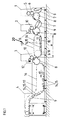
- a sheet-fed rotary printing press is in its initial training shown in Figure 1 in a row.
- the transfer cylinders 7 or turning systems are sheet guiding devices at defined intervals 9 assigned.
- Figure 1 is a section of such a printing press shown for inline finishing. It is only a last printing unit 1 with a plate cylinder 5, one Blanket cylinder 6 and the impression cylinder 8 as a sheet guide cylinder shown.
- the plate cylinder 5 is an inking unit and possibly assigned a dampening system.
- the printing unit 1 is a first coating unit in the conveying direction 17 2 downstream, which by a forme cylinder 10 and a Dosing system 11, e.g. a two-roll mill is formed.
- the Forme cylinder 10 is in turn a printing cylinder 8 as a sheet guide cylinder assigned.
- Between the printing unit 1 and the first coating unit 2 is a transfer cylinder 7 for sheet transport arranged with associated sheet guide device 9.
- the first coating unit 2 is preferably a module arranged after a length a dryer unit 20, which will be discussed in more detail later.
- the dryer unit 20 follows in the conveying direction 17 a second coating unit 3 with a Forme cylinder 10 and a dosing system 12, e.g. a chamber squeegee with a screened application roller.
- the second coating unit 3 follows in delivery direction 17 a boom 4, which the sheet-shaped printing material with endless conveyor systems 19 with sheet holding systems 16 arranged thereon, preferably Gripper systems, in a known manner a boom stack feeds and stores there.
- a sheet guide device 9 in one defined distance to the sheet holding systems 16 and above the lower runs there is at least one dryer system 14, 15, for example radiator systems, hot air dryer systems, E-field supported dryer, arranged.
- the dryer unit 20 is formed in an aggregate construction by endless revolving conveying means 13, which represent a traction mechanism gear.
- the conveying means 13 are preferably designed as horizontally extending and preferably disk-shaped deflection elements 18, for example chain wheels, traction means strands wrapping at a defined angle, for example roller chains.
- sheet holding systems 16, preferably gripper systems are arranged at defined intervals for the sheet transport.
- At least one dryer system 14, 15, especially the lower runs of the conveying means 13, is assigned in parallel to the horizontally arranged runs.
- a sheet guiding device 9 is arranged in parallel below the conveying means 13.
- the axis centers of the deflection elements 18 are in relation to one another preferably arranged in a common plane. Farther these axis centers are preferably in a common one Plane with the axis centers of the transfer cylinders 7 arranged.
- the rack-mounted and with a drive coupled deflection elements 18 are preferably approximately same outer diameter, so that load and Empty run of the conveying means 13 between the deflection elements 18 arranged essentially horizontally and parallel to each other are.
- the deflection elements 18 to the transfer cylinders 7 with approximately the same diameters executable.
- the dryer systems 14, 15 are preferably aligned in one Level above the lower run of the funding 13 between the deflection elements 18 arranged.
- the essentially horizontally running sheet guiding device 9 is arranged at a defined distance and can be acted upon by suction and / or blown air by means of a pneumatic system to support the sheet guidance.
- the printing material can be conveyed approximately parallel to the dryer systems 14, 15.
- a further dryer device can be integrated as a module in the guide surface of the sheet guide device 9.
- Such training is known from DE 196 51 406 C1. This allows drying of the sheet material on both sides.
- the dryer unit 20 is universal between two sheet guide cylinders, preferably the pressure cylinders 8, two Printing units 1 or between the sheet guiding cylinders two Coating units 2, 3 or between the sheet guiding cylinders Printing unit 1 and a coating unit 2 or 3 can be arranged.
- the dryer unit 20 is also between the sheet guide cylinders a printing unit 1 or a coating unit 2, 3 and a preferably downstream processing unit 23, e.g. a numbering unit, a pollination unit or a cutting / perforating or punching unit can be arranged.
- the processing unit 23 as a module (in Unit design) trained.
- a preferred arrangement results from the fact that between a last printing unit 1 in the conveying direction 17 and one a coating unit 20 according to the invention is arranged.
- the direct arrangement of the dryer unit 20 after the last printing unit 1 has the particular advantage that the applied to the sheet-shaped printing material Multi-color printing has dried better before the varnish is applied. During the subsequent application of at least one paint job such a dried substrate clearly receives one higher gloss effect.
- the length a of the dryer unit 20 is preferably variable in length executable so that between the deflection elements 18 sufficient space for one or more dryer systems 14, 15 or for an extension per se.
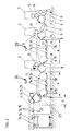
- FIG. 2 a section of a printing machine for inline finishing is shown in a second embodiment with a last printing unit 1 with plate cylinder 5, blanket cylinder 6 and printing cylinder 8 (sheet guiding cylinder).
- the printing unit 1 is followed in the conveying direction 17 by a first coating unit 2 analogous to the first embodiment.
- a transfer cylinder 7 for sheet transport with an associated sheet guiding device 9 is arranged.
- the first coating unit 2 is a first, preferably as a module trained dryer unit 20 downstream, in the conveying direction 17 a second coating unit 3 with forme cylinder 10 and Dosing system 12 follows.
- the second coating unit 3 follows in the conveying direction 17 a second, preferably designed as a module Dryer unit 20.
- the modules are designed as modules Dryer units 20 are preferably constructed identically.
- Each dryer unit 20 is designed in a unit construction and has endlessly rotating conveying means 13 with two deflecting elements 18 and horizontally arranged runs as well as in Defined distances arranged sheet holding systems 16.
- At least one dryer system 14, 15 is the lower one Trums of funding 13 assigned in parallel and at least in the area of the dryer systems 14, 15 below the funding 13 is a sheet guiding device 9 in parallel arranged.
- a processing unit 23 Downstream of the second dryer unit 20 is a processing unit 23, preferably a module with a length b, which is followed by an extension arm 4.
- the processing unit 23 has, as a module, side walls arranged between the dryer unit 20 and the delivery arm 4, which carry a mounted, sheet-guiding transfer cylinder 22 and an adjacent, mounted cylinder 21.
- the cylinder 21 serves, for example, as an embossing cylinder, punching / perforating cylinder, numbering cylinder or calender, etc.
- a dryer system 14, 15, adjacent to the transfer cylinder 22, is arranged downstream of the cylinder 21.
- a waste delivery is preferably assigned to the transfer cylinder 22, and the transfer cylinder 22 is followed by a preferably horizontally rotating conveyor system 19 with sheet holding systems 16 in the delivery 4.
- At least one dryer system 14, 15 is preferably arranged above the lower run, a sheet guiding device 9 being arranged below the lower run.
- the mode of operation is as follows: The printing material is transferred in the conveying direction 17 from a sheet holding system of the printing cylinder 8 to a sheet holding system 16 of the conveying system 13.
- the sheet holding system 16 guides the fixed printing material into the sheet outlet (below the upstream deflection element 18), the printing material is guided along the dryer system 14, 15 in one plane and dried uniformly.
- the sheet guiding device 9 supports the printing material so that it is guided approximately horizontally without contact and into the sheet emergence (downstream deflection element 18) and preferably in a noticeably dried state to a sheet holding system of the downstream printing cylinder 8, preferably of the second coating unit 3, for further processing is handed over.
- the printing material is then transferred to a sheet holding system 16 of the conveyor system 19 and transported to the delivery stack.
- the printing material is transferred to a sheet holding system 16 of the conveying means 13 (second dryer unit 20) and from there to a sheet holding system of the transfer cylinder 22 for further processing.
- the printing material is transferred from the transfer cylinder 22 to the conveyor system 19 and transported to the delivery stack.
Landscapes
- Engineering & Computer Science (AREA)
- Mechanical Engineering (AREA)
- Supply, Installation And Extraction Of Printed Sheets Or Plates (AREA)
- Drying Of Solid Materials (AREA)
- Feeding Of Articles By Means Other Than Belts Or Rollers (AREA)
Abstract
Description
Von Nachteil ist hierbei, dass diese Ausbildung auf den Ausleger einer Druckmaschine beschränkt ist und dass im Bereich der Trocknerstrecke der Bogen lediglich an einer Kante in Greifern fixiert, ohne Bogenführung, frei geführt ist, so dass sich der Abstand zwischen den zu trocknenden Bogen und dem Trocknersystem unkontrolliert vergrößert und der Wirkungsgrad des Trocknersystems reduziert ist.
Gleichzeitig wird durch die erfindungsgemäße Ausbildung die Trocknerstrecke verlängert und die Gefahr des Abschmierens des Bedruckstoffes in Folge zu geringer Trocknung von Farbe und/oder Lack oder eine Überhitzung des Bedruckstoffes spürbar reduziert.
- Fig. 1
- eine Bogenrotationsdruckmaschine (Ausschnitt) in erster Ausbildung,
- Fig. 2
- eine Bogenrotationsdruckmaschine (Ausschnitt) in zweiter Ausbildung.
Den horizontal angeordneten Trums ist wenigstens ein Trocknersystem 14, 15, speziell den unteren Trums der Fördermittel 13, parallel zugeordnet. Zumindest im Bereich der Trocknersysteme 14, 15 ist unterhalb der Fördermittel 13 dazu parallel eine Bogenleiteinrichtung 9 angeordnet.
In einer weiteren Ausbildung ist in der Leitfläche der Bogenleiteinrichtung 9 eine weitere Trocknervorrichtung als Modul integriert anordenbar. Eine derartige Ausbildung ist aus DE 196 51 406 C1 bekannt. Damit ist eine beidseitige Trocknung des Bogenmaterials erzielbar.
Dem Druckwerk 1 ist in Förderrichtung 17 ein erstes Lackwerk 2 analog zur ersten Ausbildung nachgeordnet. Zwischen dem Druckwerk 1 und dem ersten Lackwerk 2 ist ein Transferzylinder 7 für den Bogentransport mit zugeordneter Bogenleiteinrichtung 9 angeordnet.
Dem Umführzylinder 22 ist bevorzugt eine Makulaturauslage zugeordnet und dem Umführzylinder 22 ist im Ausleger 4 ein bevorzugt horizontal umlaufendes Fördersystem 19 mit Bogenhaltesystemen 16 nachgeordnet. Oberhalb des unteren Trums ist bevorzugt wenigstens ein Trocknersystem 14,15 angeordnet, wobei unterhalb des unteren Trums eine Bogenleiteinrichtung 9 angeordnet ist.
In erster Ausbildung wird danach der Bedruckstoff an ein Bogenhaltesystem 16 des Fördersystems 19 übergeben und zum Auslegerstapel transportiert.
In zweiter Ausbildung wird der Bedruckstoff an ein Bogenhaltesystem 16 der Fördermittel 13 (zweite Trocknereinheit 20) übergeben und von dort an ein Bogenhaltesystem des Umführzylinders 22 zur weiteren Verarbeitung übergeben. Vom Umführzylinder 22 wird der Bedruckstoff an das Fördersystem 19 übergeben und zum Auslegerstapel transportiert.
- 1
- Druckwerk
- 2
- erstes Lackwerk
- 3
- zweites Lackwerk
- 4
- Ausleger
- 5
- Plattenzylinder
- 6
- Gummituchzylinder
- 7
- Transferzylinder
- 8
- Druckzylinder
- 9
- Bogenleiteinrichtung
- 10
- Formzylinder
- 11
- Dosiersystem
- 12
- Dosiersystem
- 13
- Fördermittel
- 14
- Trocknersystem
- 15
- Trocknersystem
- 16
- Bogenhaltesystem
- 17
- Förderrichtung
- 18
- Umlenkelement
- 19
- Fördersystem
- 20
- Trocknereinheit
- 21
- Zylinder
- 22
- Umführzylinder
- 23
- Verarbeitungseinheit
- a
- Länge (Trocknermodul)
- b
- Länge (Verarbeitungsmodul)
Claims (10)
- Trocknereinheit in einer Bogenrotationsdruckmaschine für den Mehrfarbendruck, welche zwischen zwei Bogenführungszylindern als Modul angeordnet ist,
dadurch gekennzeichnet,dass die Trocknereinheit (20) in Aggregatbauweise endlos umlaufende Fördermittel (13) mit zwei Umlenkelementen (18) und horizontal angeordneten Trums sowie in definierten Abständen angeordnete Bogenhaltesysteme (16) aufweist,dass wenigstens ein Trocknersystem (14, 15) den unteren Trums der Fördermittel (13) parallel zugeordnet ist, und dass zumindest im Bereich der Trocknersysteme (14, 15) unterhalb der Fördermittel (13) parallel eine Bogenleiteinrichtung (9) angeordnet ist. - Trocknereinheit nach Anspruch 1,
dadurch gekennzeichnet,
dass die Umlenkelemente (18) einen gleichen Außendurchmesser aufweisen. - Trocknereinheit nach Anspruch 1 und 2,
dadurch gekennzeichnet,
dass die Umlenkelemente (18) den gleichen Außendurchmesser wie die Bogenführungszylinder (7) aufweisen. - Trocknereinheit nach wenigstens Anspruch 1,
dadurch gekennzeichnet,
dass die Achsmittelpunkte der Umlenkelemente (18) in einer Ebene angeordnet sind. - Trocknereinheit nach wenigstens Anspruch 1 und 4,
dadurch gekennzeichnet,
dass die Achsmittelpunkte der Umlenkelemente (18) und die Achsmittelpunkte der Bogenführungszylinder (7) in einer Ebene angeordnet sind. - Trocknereinheit nach wenigstens Anspruch 1,
dadurch gekennzeichnet,
dass die Trocknereinheit (20) zwischen einem Druckwerk (1) oder Lackwerk (2,3) und einer Verarbeitungseinheit (23) angeordnet ist. - Trocknereinheit nach wenigstens Anspruch 1,
dadurch gekennzeichnet,
dass die Trocknereinheit (20) zwischen zwei Druckwerken (1) angeordnet ist. - Trocknereinheit nach wenigstens Anspruch 1,
dadurch gekennzeichnet,
dass die Trocknereinheit (20) zwischen zwei Lackwerken (2, 3) angeordnet ist. - Trocknereinheit nach wenigstens Anspruch 1,
dadurch gekennzeichnet,
dass die Trocknereinheit (20) zwischen einem Druckwerk (1) und einem Lackwerk (2 oder 3) angeordnet ist. - Trocknereinheit nach wenigstens Anspruch 1,
dadurch gekennzeichnet,
dass einer Trocknereinheit (20) in Förderrichtung (17) eine zumindest einen Bogenführungszylinder (22) aufweisende Verarbeitungseinheit (23) als Modul nachgeordnet ist.
Applications Claiming Priority (4)
| Application Number | Priority Date | Filing Date | Title |
|---|---|---|---|
| DE10009694 | 2000-02-29 | ||
| DE10009694 | 2000-02-29 | ||
| DE10106529A DE10106529A1 (de) | 2000-02-29 | 2001-02-13 | Trocknereinheit in einer Bogenrotationsdruckmaschine |
| DE10106529 | 2001-02-13 |
Publications (3)
| Publication Number | Publication Date |
|---|---|
| EP1129850A2 true EP1129850A2 (de) | 2001-09-05 |
| EP1129850A3 EP1129850A3 (de) | 2004-01-07 |
| EP1129850B1 EP1129850B1 (de) | 2006-12-13 |
Family
ID=26004592
Family Applications (1)
| Application Number | Title | Priority Date | Filing Date |
|---|---|---|---|
| EP01104085A Expired - Lifetime EP1129850B1 (de) | 2000-02-29 | 2001-02-21 | Trocknereinheit in einer Bogenrotationsdruckmaschine |
Country Status (3)
| Country | Link |
|---|---|
| EP (1) | EP1129850B1 (de) |
| AT (1) | ATE348002T1 (de) |
| DE (1) | DE50111605D1 (de) |
Family Cites Families (5)
| Publication number | Priority date | Publication date | Assignee | Title |
|---|---|---|---|---|
| US2174865A (en) * | 1937-07-21 | 1939-10-03 | Cottrell C B & Sons Co | Sheet-fed rotary perfecting printing press |
| DE1260482B (de) * | 1966-05-21 | 1968-02-08 | Roland Offsetmaschf | Bogendruckmaschine mit einer Vorrichtung zum Trocknen bedruckter Bogen |
| CH480175A (de) * | 1969-04-21 | 1969-10-31 | De La Rue Giori Sa | Mehrfarben-Stahlstichdruckmaschine für Bogen, insbesondere für Wertscheine |
| DE4218421A1 (de) * | 1992-06-04 | 1993-12-09 | Heidelberger Druckmasch Ag | Bogenführung im Ausleger einer Druckmaschine |
| DE19629370A1 (de) * | 1996-07-20 | 1998-01-22 | Heidelberger Druckmasch Ag | Rotationsdruckmaschine mit einer Einrichtung zum Behandeln der Oberfläche von Bogen |
-
2001
- 2001-02-21 EP EP01104085A patent/EP1129850B1/de not_active Expired - Lifetime
- 2001-02-21 AT AT01104085T patent/ATE348002T1/de not_active IP Right Cessation
- 2001-02-21 DE DE50111605T patent/DE50111605D1/de not_active Expired - Lifetime
Also Published As
| Publication number | Publication date |
|---|---|
| ATE348002T1 (de) | 2007-01-15 |
| EP1129850B1 (de) | 2006-12-13 |
| DE50111605D1 (de) | 2007-01-25 |
| EP1129850A3 (de) | 2004-01-07 |
Similar Documents
| Publication | Publication Date | Title |
|---|---|---|
| EP0819521B1 (de) | Rotationsdruckmaschine mit einer Einrichtung zum Behandeln der Oberfläche von Bogen | |
| EP1147893B2 (de) | Bogen-Rotationsdruckmaschine mit einem Multifunktionsmodul | |
| EP0878301B1 (de) | Abschmierfreier Bogentransport in einer Rotationsdruckmaschine | |
| EP0674992B1 (de) | Trocknervorrichtung für eine Bogenrotationsdruckmaschine | |
| DE19857984B4 (de) | Mit Excimer-Strahlern arbeitender Trockner in Bogendruckmaschinen | |
| DE19523881C2 (de) | Rotationsdruckmaschine mit nachgeschalteter Weiterverarbeitungseinheit | |
| DE19753089C2 (de) | Bogenführungseinrichtung in einer Druckmaschine | |
| EP0978467A2 (de) | Ausleger für eine Druckmaschine | |
| EP0924069B1 (de) | Bogenführungseinrichtung in einer Druckmaschine | |
| EP1151860A1 (de) | Bogendruckmaschine | |
| DE10232255A1 (de) | Rotationsdruckmaschine | |
| EP0922577B1 (de) | Bogenführungseinrichtung in einer Druckmaschine | |
| DE10047394A1 (de) | Modulares Druckmaschinensystem zum Bedrucken von Bogen | |
| DE19949751A1 (de) | Modulares Druckmaschinensystem zum Bedrucken von Bogen | |
| EP1285755B1 (de) | Beschichtungsmaschine zum Veredeln von Druckbogen | |
| EP1075947B1 (de) | Bogenführungseinrichtung in einer Druckmaschine | |
| EP1129850B1 (de) | Trocknereinheit in einer Bogenrotationsdruckmaschine | |
| EP0968821A2 (de) | Bogentransportzylinder in einer Bogenrotationsdruckmaschine | |
| DE10106529A1 (de) | Trocknereinheit in einer Bogenrotationsdruckmaschine | |
| DE19752492C2 (de) | Bogenführungseinrichtung in einer Druckmaschine | |
| EP1502739B1 (de) | Trocknerssystem für bogenförmige Bedruckstoffe in einer Rotationsdruckmaschine | |
| EP0922575B1 (de) | Bogenführungseinrichtung in einer Druckmaschine | |
| EP1916107A2 (de) | Vorrichtung und Verfahren zur veredelnden Bearbeitung von bogenförmigen Substraten in einer Bogendruckmaschinen | |
| DE2237567A1 (de) | Mehrfarben-rotationsblechtafeldruckmaschine | |
| DE10158050A1 (de) | Verfahren und Vorrichtung zum Abkühlen eines Bedruckstoffes in einer Rotationsdruckmaschine |
Legal Events
| Date | Code | Title | Description |
|---|---|---|---|
| PUAI | Public reference made under article 153(3) epc to a published international application that has entered the european phase |
Free format text: ORIGINAL CODE: 0009012 |
|
| AK | Designated contracting states |
Kind code of ref document: A2 Designated state(s): AT BE CH CY DE DK ES FI FR GB GR IE IT LI LU MC NL PT SE TR |
|
| AX | Request for extension of the european patent |
Free format text: AL;LT;LV;MK;RO;SI |
|
| PUAL | Search report despatched |
Free format text: ORIGINAL CODE: 0009013 |
|
| AK | Designated contracting states |
Kind code of ref document: A3 Designated state(s): AT BE CH CY DE DK ES FI FR GB GR IE IT LI LU MC NL PT SE TR |
|
| AX | Request for extension of the european patent |
Extension state: AL LT LV MK RO SI |
|
| 17P | Request for examination filed |
Effective date: 20031220 |
|
| AKX | Designation fees paid |
Designated state(s): AT BE CH CY DE DK ES FI FR GB GR IE IT LI LU MC NL PT SE TR |
|
| 17Q | First examination report despatched |
Effective date: 20050331 |
|
| GRAP | Despatch of communication of intention to grant a patent |
Free format text: ORIGINAL CODE: EPIDOSNIGR1 |
|
| GRAS | Grant fee paid |
Free format text: ORIGINAL CODE: EPIDOSNIGR3 |
|
| GRAA | (expected) grant |
Free format text: ORIGINAL CODE: 0009210 |
|
| AK | Designated contracting states |
Kind code of ref document: B1 Designated state(s): AT BE CH CY DE DK ES FI FR GB GR IE IT LI LU MC NL PT SE TR |
|
| PG25 | Lapsed in a contracting state [announced via postgrant information from national office to epo] |
Ref country code: IT Free format text: LAPSE BECAUSE OF FAILURE TO SUBMIT A TRANSLATION OF THE DESCRIPTION OR TO PAY THE FEE WITHIN THE PRESCRIBED TIME-LIMIT;WARNING: LAPSES OF ITALIAN PATENTS WITH EFFECTIVE DATE BEFORE 2007 MAY HAVE OCCURRED AT ANY TIME BEFORE 2007. THE CORRECT EFFECTIVE DATE MAY BE DIFFERENT FROM THE ONE RECORDED. Effective date: 20061213 Ref country code: FI Free format text: LAPSE BECAUSE OF FAILURE TO SUBMIT A TRANSLATION OF THE DESCRIPTION OR TO PAY THE FEE WITHIN THE PRESCRIBED TIME-LIMIT Effective date: 20061213 Ref country code: NL Free format text: LAPSE BECAUSE OF FAILURE TO SUBMIT A TRANSLATION OF THE DESCRIPTION OR TO PAY THE FEE WITHIN THE PRESCRIBED TIME-LIMIT Effective date: 20061213 Ref country code: IE Free format text: LAPSE BECAUSE OF FAILURE TO SUBMIT A TRANSLATION OF THE DESCRIPTION OR TO PAY THE FEE WITHIN THE PRESCRIBED TIME-LIMIT Effective date: 20061213 Ref country code: DK Free format text: LAPSE BECAUSE OF FAILURE TO SUBMIT A TRANSLATION OF THE DESCRIPTION OR TO PAY THE FEE WITHIN THE PRESCRIBED TIME-LIMIT Effective date: 20061213 |
|
| REG | Reference to a national code |
Ref country code: GB Ref legal event code: FG4D Free format text: NOT ENGLISH |
|
| REG | Reference to a national code |
Ref country code: CH Ref legal event code: EP |
|
| REG | Reference to a national code |
Ref country code: IE Ref legal event code: FG4D Free format text: LANGUAGE OF EP DOCUMENT: GERMAN |
|
| REF | Corresponds to: |
Ref document number: 50111605 Country of ref document: DE Date of ref document: 20070125 Kind code of ref document: P |
|
| PG25 | Lapsed in a contracting state [announced via postgrant information from national office to epo] |
Ref country code: CH Free format text: LAPSE BECAUSE OF NON-PAYMENT OF DUE FEES Effective date: 20070228 Ref country code: MC Free format text: LAPSE BECAUSE OF NON-PAYMENT OF DUE FEES Effective date: 20070228 Ref country code: LI Free format text: LAPSE BECAUSE OF NON-PAYMENT OF DUE FEES Effective date: 20070228 |
|
| PG25 | Lapsed in a contracting state [announced via postgrant information from national office to epo] |
Ref country code: SE Free format text: LAPSE BECAUSE OF FAILURE TO SUBMIT A TRANSLATION OF THE DESCRIPTION OR TO PAY THE FEE WITHIN THE PRESCRIBED TIME-LIMIT Effective date: 20070313 |
|
| PG25 | Lapsed in a contracting state [announced via postgrant information from national office to epo] |
Ref country code: ES Free format text: LAPSE BECAUSE OF FAILURE TO SUBMIT A TRANSLATION OF THE DESCRIPTION OR TO PAY THE FEE WITHIN THE PRESCRIBED TIME-LIMIT Effective date: 20070324 |
|
| PG25 | Lapsed in a contracting state [announced via postgrant information from national office to epo] |
Ref country code: PT Free format text: LAPSE BECAUSE OF FAILURE TO SUBMIT A TRANSLATION OF THE DESCRIPTION OR TO PAY THE FEE WITHIN THE PRESCRIBED TIME-LIMIT Effective date: 20070514 |
|
| NLV1 | Nl: lapsed or annulled due to failure to fulfill the requirements of art. 29p and 29m of the patents act | ||
| GBV | Gb: ep patent (uk) treated as always having been void in accordance with gb section 77(7)/1977 [no translation filed] |
Effective date: 20061213 |
|
| EN | Fr: translation not filed | ||
| REG | Reference to a national code |
Ref country code: CH Ref legal event code: PL |
|
| PLBE | No opposition filed within time limit |
Free format text: ORIGINAL CODE: 0009261 |
|
| STAA | Information on the status of an ep patent application or granted ep patent |
Free format text: STATUS: NO OPPOSITION FILED WITHIN TIME LIMIT |
|
| 26N | No opposition filed |
Effective date: 20070914 |
|
| PG25 | Lapsed in a contracting state [announced via postgrant information from national office to epo] |
Ref country code: GB Free format text: LAPSE BECAUSE OF FAILURE TO SUBMIT A TRANSLATION OF THE DESCRIPTION OR TO PAY THE FEE WITHIN THE PRESCRIBED TIME-LIMIT Effective date: 20061213 |
|
| BERE | Be: lapsed |
Owner name: MAN ROLAND DRUCKMASCHINEN A.G. Effective date: 20070228 |
|
| PG25 | Lapsed in a contracting state [announced via postgrant information from national office to epo] |
Ref country code: BE Free format text: LAPSE BECAUSE OF NON-PAYMENT OF DUE FEES Effective date: 20070228 |
|
| PG25 | Lapsed in a contracting state [announced via postgrant information from national office to epo] |
Ref country code: FR Free format text: LAPSE BECAUSE OF FAILURE TO SUBMIT A TRANSLATION OF THE DESCRIPTION OR TO PAY THE FEE WITHIN THE PRESCRIBED TIME-LIMIT Effective date: 20070803 Ref country code: GR Free format text: LAPSE BECAUSE OF FAILURE TO SUBMIT A TRANSLATION OF THE DESCRIPTION OR TO PAY THE FEE WITHIN THE PRESCRIBED TIME-LIMIT Effective date: 20070314 |
|
| PG25 | Lapsed in a contracting state [announced via postgrant information from national office to epo] |
Ref country code: FR Free format text: LAPSE BECAUSE OF FAILURE TO SUBMIT A TRANSLATION OF THE DESCRIPTION OR TO PAY THE FEE WITHIN THE PRESCRIBED TIME-LIMIT Effective date: 20061213 |
|
| PG25 | Lapsed in a contracting state [announced via postgrant information from national office to epo] |
Ref country code: CY Free format text: LAPSE BECAUSE OF FAILURE TO SUBMIT A TRANSLATION OF THE DESCRIPTION OR TO PAY THE FEE WITHIN THE PRESCRIBED TIME-LIMIT Effective date: 20061213 Ref country code: LU Free format text: LAPSE BECAUSE OF NON-PAYMENT OF DUE FEES Effective date: 20070221 |
|
| PG25 | Lapsed in a contracting state [announced via postgrant information from national office to epo] |
Ref country code: TR Free format text: LAPSE BECAUSE OF FAILURE TO SUBMIT A TRANSLATION OF THE DESCRIPTION OR TO PAY THE FEE WITHIN THE PRESCRIBED TIME-LIMIT Effective date: 20061213 |
|
| PGFP | Annual fee paid to national office [announced via postgrant information from national office to epo] |
Ref country code: AT Payment date: 20100212 Year of fee payment: 10 |
|
| PG25 | Lapsed in a contracting state [announced via postgrant information from national office to epo] |
Ref country code: AT Free format text: LAPSE BECAUSE OF NON-PAYMENT OF DUE FEES Effective date: 20110221 |
|
| PGFP | Annual fee paid to national office [announced via postgrant information from national office to epo] |
Ref country code: DE Payment date: 20120323 Year of fee payment: 12 |
|
| REG | Reference to a national code |
Ref country code: DE Ref legal event code: R081 Ref document number: 50111605 Country of ref document: DE Owner name: MANROLAND SHEETFED GMBH, DE Free format text: FORMER OWNER: MANROLAND AG, 63075 OFFENBACH, DE Effective date: 20120509 |
|
| REG | Reference to a national code |
Ref country code: DE Ref legal event code: R119 Ref document number: 50111605 Country of ref document: DE Effective date: 20130903 |
|
| PG25 | Lapsed in a contracting state [announced via postgrant information from national office to epo] |
Ref country code: DE Free format text: LAPSE BECAUSE OF NON-PAYMENT OF DUE FEES Effective date: 20130903 |