EP1129864A1 - Aktenordner - Google Patents
Aktenordner Download PDFInfo
- Publication number
- EP1129864A1 EP1129864A1 EP00490009A EP00490009A EP1129864A1 EP 1129864 A1 EP1129864 A1 EP 1129864A1 EP 00490009 A EP00490009 A EP 00490009A EP 00490009 A EP00490009 A EP 00490009A EP 1129864 A1 EP1129864 A1 EP 1129864A1
- Authority
- EP
- European Patent Office
- Prior art keywords
- rib
- file
- ribs
- flaps
- internal
- Prior art date
- Legal status (The legal status is an assumption and is not a legal conclusion. Google has not performed a legal analysis and makes no representation as to the accuracy of the status listed.)
- Withdrawn
Links
- 210000002105 tongue Anatomy 0.000 claims description 11
- 230000000295 complement effect Effects 0.000 claims description 7
- 238000007596 consolidation process Methods 0.000 claims description 6
- 238000005728 strengthening Methods 0.000 claims description 3
- 230000002787 reinforcement Effects 0.000 claims description 2
- 230000000284 resting effect Effects 0.000 claims 1
- 239000011230 binding agent Substances 0.000 description 8
- 239000000463 material Substances 0.000 description 4
- 239000000243 solution Substances 0.000 description 3
- 238000004519 manufacturing process Methods 0.000 description 2
- 230000003014 reinforcing effect Effects 0.000 description 2
- 239000011324 bead Substances 0.000 description 1
- 230000005489 elastic deformation Effects 0.000 description 1
- 238000001746 injection moulding Methods 0.000 description 1
- 238000002955 isolation Methods 0.000 description 1
- 238000005304 joining Methods 0.000 description 1
- 238000000034 method Methods 0.000 description 1
- 230000002093 peripheral effect Effects 0.000 description 1
- 238000011084 recovery Methods 0.000 description 1
Images


Classifications
-
- B—PERFORMING OPERATIONS; TRANSPORTING
- B42—BOOKBINDING; ALBUMS; FILES; SPECIAL PRINTED MATTER
- B42F—SHEETS TEMPORARILY ATTACHED TOGETHER; FILING APPLIANCES; FILE CARDS; INDEXING
- B42F13/00—Filing appliances with means for engaging perforations or slots
- B42F13/0006—Covers for loose-leaf binders
Definitions
- the present invention relates to a filing cabinet intended for all types of documents, such as sheets, loose-leaf, perforated or not.
- binders are generally consisting of a back and two flat side faces extending on either side on the other of said back. They can be fitted with fasteners such as by example of the rings to keep the documents stored.
- a first solution to this problem was provided by the plaintiff by proposing a binder with increased stability when in an upright position.
- Such a filing cabinet has the particularity of having faces lateral which are extended at their distal ends by flaps converging so as to ensure said stability in a vertical position, even loaded.
- the object of the present invention is to propose a workbook manufacturing as simple as the previous one but with means strengthening its structure capable of giving it even greater rigidity, hence better squaring without resorting to means reported.
- Another object of the invention is to propose a workbook of which the thickness of the material used is not more important, and which can be obtained for example by injection molding of a plastic material during the same operation, that is to say without recovery.
- the invention relates to a file consisting of a back from the longitudinal sides of which extend two lateral faces of which the distal ends are shaped into converging flaps, as well as closing means, the assembly cooperating so as to ensure stability said filing cabinet in vertical position by looping its volume on itself, characterized in that a plurality of reinforcing ribs are formed in a hollow or curved shape on at least one of its lateral faces of so as to increase the rigidity of the assembly.
- the present invention also relates to characteristics which will emerge during the description which follows, and which one should be considered in isolation or in any combination possible techniques.
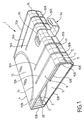
- Workbook 1 broadly designated in Figure 1, is consisting of a back 2, in particular rectangular, from the sides longitudinal 3 and 4 from which two lateral faces 5 and 6 extend.
- the distal ends of the lateral faces 5 and 6 are shaped as converging flaps 7 and 8 which may or may not be contiguous, and have closure means 9a, 9b.
- a plurality of reinforcing ribs are formed in hollow 14 or in convex 10 on at least one of the lateral faces. Naturally, the stiffness will increased by the presence of the ribs on the two faces 5 and 6.
- the ribs 10A, 10B are produced in a transverse direction and extend from the same way on the converging flaps 7 and 8.
- the ribs 10A, 10B of each of the side faces 5 and 6 are interrupted at a distance from the back 2 in order to release a surface 13 intended for the production of a rib 14, in a different direction, in an area proximal of said back 2.
- the rib 14 proximal of the back 2 describes an arc of a circle, the cord of which consists of a longitudinal edge 4 of the back 2.
- the transverse and parallel ribs of a lateral face extend from uninterrupted manner on the back then on the other side face to close on themselves at the junction edges of the flaps.
- edges upper and lower back 2, side faces 5, 6 and flaps 7, 8, delimiting corresponding open sides are reinforced by a rib double end 15A, 15B directed inwards and outwards.
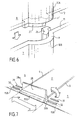
- the ribs transverse 10 made at least on the side faces 5 and 6 and extending on the adjoining flaps, in this case 7 and 8 to meet at level of their junction edges 11 and 12, have in their plane coming opposite, additional positioning and / or connecting means from one to the other, so as to allow cooperation between the ribs 10A on one side, and ribs 10B on the other side during the closure, and thus consolidate the general squareness of the binder 1, in particular by making them one with the other.
- these means for positioning and / or connecting a rib 10A compared to another 10B are constituted by a tenonmortaise system, constituted by a stud 16, coming from the plane P of the rib 10B, of reduced section with respect to it, and forming a form base parallelepipedic, part of which is directed towards the external surface of a rib 10B is extended by a semi-cylindrical part 17.
- Said stud 16 is able to cooperate with a recess 18 of complementary shape made on the end of the other rib 10A with which it is intended to come in closing link.
- Said pad 16 will possibly be extended, in width, towards the back 2 of the filing cabinet, and / or in height, towards the lateral face carrying the rib from which it came.
- Such studs 16 may be provided on each of the converging flaps so as to alternate, undit pad 16 being followed on the same flap by said recess 18, the other flap being equipped with consequence vis-à-vis.
- these means for positioning and / or connecting a rib 10A relative to another 10B are constituted by a stud 19 produced inside of a convex rib 10B and emerging from both the upper plane P of this and the internal plane P 'of the flap 7 on which it is made, so to constitute a relief in relief capable of cooperating with a recess 20 of complementary shape made on the end of the other rib 10A with which it is intended to come into connection in closing.
- the pad 19 has two sides flat sides and a semi-cylindrical apex 19a.
- these means for positioning and / or connecting a rib 10A compared to another 10B are constituted by a stud 21 in two parts 21A, 21 B produced inside a convex rib 10B and emerging at the same time of the plane P thereof and of the internal plane P 'of the flap 7 on which it is carried out.
- the two parts 21A, 21B of the pad 21 are generally in form of cylindrical crown sectors spaced from each other to delimit a mortise 22 able to receive a post 23 of shape corresponding made in relief on the plane P of the other rib 10A, opposite.
- connection is made by embedding a stud 23 of a rib 10A in the mortise 22 of the other 10B, which takes place simultaneously to the embedding of the sectors of cylindrical crowns 21A, 21B of this same rib 10B in two hollow internal parts 24, 25 on the other rib 10B located on either side of its stud 23.
- the means for positioning and / or connecting a rib 10A by compared to another 10B are constituted by two studs 26, 27 complementary carried out head to tail respectively inside a convex rib 10B and inside another similar rib 10A located opposite.
- the pads 26, 27 are generally in the form of sectors of cylindrical crowns and emerge from both the respective planes P and P 'of each rib 10A, 10B and of the respective internal plane of each flap 7 and 8, so as to join in a complementary way when closing respectively accommodating in the remaining internal free parts of said ribs to be joined at all points.
- the consolidation general squaring can be improved through at least one internal tongue 28, or 33-34, from the internal face of the back 2 nearby immediately from its longitudinal edges 3 and 4, in its lower zone and / or in its upper zone, to constitute a stop and setting surface support of the side faces 5 and 6 when closing.
- the tongue 28, constituting the stops internal of faces 5 and 6 is generally parallelepiped and arranged transversely to the back 2 across its width to join its two longitudinal edges 3 and 4.
- each tongue 28 of the back 2 directed towards the side faces 5 or 6, are framed on either side when closing, by bosses 29, 30 and 31, 32, made transversely inside of said lateral faces 5 and 6 according to a spacing corresponding to the width of the tongue 28, so as to contribute to strengthening the squareness of all.
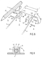
- the back 2 has two stops arranged on its inner face in its upper zone and in its lower zone and consist of two tongues 33, 34 generally parallelepipedic arranged longitudinally and opposite and in the immediate vicinity of the edges longitudinal 3, 4 of said back 2.
- At least one of the longitudinal tabs 33, 34 is lined with second longitudinal tongue 35, 36 which is parallel to it in particular according to a spacing of value substantially equal to that of the diameter of a pencil 37, so as to constitute a support for the latter.
- the tabs 33 and 35 cooperate at their upper free end with beads 42 and 43, making it possible to retain the pencil 37 after passage of these made possible by elastic deformation.
- the lateral ends 33a, 33b or 34a, 34b of each tab 33 or 34 of the back 2 perpendicular to the side faces 5 or 6 are framed on the side and else to the closure by bosses 38, 39, 40, 41, made transversely inside said lateral faces 5 and 6, according to a spacing corresponding to the length of the tabs 33, 34 so as to constitute a reinforcement of the squareness of the whole.
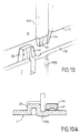
- said additional positioning means provided at the ribs 10A, 10B are formed by studs 44, 45, in particular in shape quadrangular pyramid trunk, projecting and recessed from at the joining edges 11, 12 of the flaps 7, 8.
- the inclined face 46, 47 of the pads 42, 43 cooperates with the faces respective internal of the opposite flaps 7, 8, in order to avoid overlapping internal and / or external of these, while allowing a certain catch-up of play.
- exemplary embodiments shown in the figures relate to a binder with mostly curved ribs.
- these ribs could also be hollow and include the same characteristics as those described above.
- the depth or thickness of a rib is 2mm, and the thickness of the lateral faces is, thanks to the invention, not more than 2mm.
- the double peripheral rib 15 is with a width of 6mm for example, that is to say that it protrudes from both sides and on the other side of the 2mm side face, said face making, as said above, 2mm.
- said binder is made of a thickness of material, in particular moldable plastic, in which the ribs 10, 14, the tabs 28 or 33-34 and / or the bosses mentioned above, among others, are made in the mass.
Landscapes
- Assembled Shelves (AREA)
Priority Applications (1)
| Application Number | Priority Date | Filing Date | Title |
|---|---|---|---|
| EP00490009A EP1129864A1 (de) | 2000-02-22 | 2000-02-22 | Aktenordner |
Applications Claiming Priority (1)
| Application Number | Priority Date | Filing Date | Title |
|---|---|---|---|
| EP00490009A EP1129864A1 (de) | 2000-02-22 | 2000-02-22 | Aktenordner |
Publications (1)
| Publication Number | Publication Date |
|---|---|
| EP1129864A1 true EP1129864A1 (de) | 2001-09-05 |
Family
ID=8174292
Family Applications (1)
| Application Number | Title | Priority Date | Filing Date |
|---|---|---|---|
| EP00490009A Withdrawn EP1129864A1 (de) | 2000-02-22 | 2000-02-22 | Aktenordner |
Country Status (1)
| Country | Link |
|---|---|
| EP (1) | EP1129864A1 (de) |
Citations (3)
| Publication number | Priority date | Publication date | Assignee | Title |
|---|---|---|---|---|
| FR934281A (fr) * | 1946-09-19 | 1948-05-18 | D Articles Metalliques Soc Ind | Perfectionnements à la fabrication des couvertures pour cahiers, carnets, feuilles mobiles, etc. |
| FR2756773A1 (fr) * | 1996-12-11 | 1998-06-12 | Ad Classement Sa | Classeur, notamment pour le rangement de documents, a stabilite amelioree |
| EP0847875A1 (de) * | 1996-12-11 | 1998-06-17 | Achat et Distribution d'Articles de Classement, "A D Classement", S.A. | Aktenordner, insbesonder für Dokumente, sowie Blätter, oder andere, eventuell perforiert |
-
2000
- 2000-02-22 EP EP00490009A patent/EP1129864A1/de not_active Withdrawn
Patent Citations (3)
| Publication number | Priority date | Publication date | Assignee | Title |
|---|---|---|---|---|
| FR934281A (fr) * | 1946-09-19 | 1948-05-18 | D Articles Metalliques Soc Ind | Perfectionnements à la fabrication des couvertures pour cahiers, carnets, feuilles mobiles, etc. |
| FR2756773A1 (fr) * | 1996-12-11 | 1998-06-12 | Ad Classement Sa | Classeur, notamment pour le rangement de documents, a stabilite amelioree |
| EP0847875A1 (de) * | 1996-12-11 | 1998-06-17 | Achat et Distribution d'Articles de Classement, "A D Classement", S.A. | Aktenordner, insbesonder für Dokumente, sowie Blätter, oder andere, eventuell perforiert |
Similar Documents
| Publication | Publication Date | Title |
|---|---|---|
| FR3104920A1 (fr) | Applicateur pour produit cosmétique, notamment du mascara, ensemble applicateur associé et procédé de fabrication d’un tel applicateur | |
| EP0944531B1 (de) | Kartonschachtel mit zentrierlaschen und zuschnitt für ihre herstellung | |
| EP3924264B1 (de) | Faltbare verpackung mit vereinfachter formgebung | |
| EP0847875B1 (de) | Aktenordner, insbesonder für Dokumente, sowie Blätter, oder andere, eventuell perforiert | |
| EP0479661B1 (de) | Schieber für Säcke, die mit zwei Eingriffsprofilen eines Plastik-Verschlusses versehen sind | |
| FR2672880A1 (fr) | Bobine de conditionnement de conducteur. | |
| EP0944481B1 (de) | Hefter, inbesondere zum ablegen aller arten von dokumenten, wie zum beispiel bögen, lose blätter und/oder ähnlichem, gegebenenfalls perforiert | |
| WO1998043883A1 (fr) | Caisse de matiere en feuille avec languettes de centrage et flan ou ensemble de flans pour la realisation d'une telle caisse | |
| WO2000014745A1 (fr) | Plateau et boitier de reception d'au moins un disque circulaire de stockage d'informations | |
| WO2001022420A1 (fr) | Boite pour disque compact | |
| FR2487103A1 (fr) | Classeur pour disques phonographiques | |
| FR2787060A1 (fr) | Classeur destine a tous types de documents, tels que feuilles, feuillets mobiles, perfores ou non | |
| EP3475177B1 (de) | Verpackung mit einem gehäuse und einer schublade, schublade für solch eine verpackung und zuschnitt für solch eine schublade | |
| EP0729428B1 (de) | Kartonschachtel mit einrichtung zum verriegeln des deckels und zuschnitt zu ihrer herstellung | |
| FR2861370A1 (fr) | Boite d'emballage pliante, renforcee | |
| FR2891491A1 (fr) | Carton a dessin | |
| FR2652062A1 (fr) | Emballage a soufflets en carton, carton ondule ou autre materiau en feuille et flan correspondant. | |
| EP0867373A1 (de) | Verpackungsschale | |
| FR2786160A1 (fr) | Palette munie d'un systeme de blocage des patins | |
| EP1186540A1 (de) | Karton mit keilförmigen Kammern | |
| FR2756772A1 (fr) | Classeur, notamment pour documents, tels que feuilles ou autres, eventuellement perforees | |
| EP0869013A1 (de) | Ausgeschnittener Zuschnitt, und aus diesem gefalteten ausgeschnittenen Zuschnitt hergestellten Hängeordner | |
| FR2749831A1 (fr) | Flan et structure de maintien et de prehension pour nappes de recipients | |
| FR2865716A1 (fr) | Recipient en matiere en feuille pliable. | |
| FR2873105A1 (fr) | Boite en papier destinee a recevoir des papiers de bureau |
Legal Events
| Date | Code | Title | Description |
|---|---|---|---|
| PUAI | Public reference made under article 153(3) epc to a published international application that has entered the european phase |
Free format text: ORIGINAL CODE: 0009012 |
|
| AK | Designated contracting states |
Kind code of ref document: A1 Designated state(s): AT BE CH CY DE DK ES FI FR GB GR IE IT LI LU MC NL PT SE |
|
| AX | Request for extension of the european patent |
Free format text: AL;LT;LV;MK;RO;SI |
|
| 17P | Request for examination filed |
Effective date: 20020226 |
|
| AKX | Designation fees paid |
Free format text: AT BE CH CY DE DK ES FI FR GB GR IE IT LI LU MC NL PT SE |
|
| 17Q | First examination report despatched |
Effective date: 20040907 |
|
| STAA | Information on the status of an ep patent application or granted ep patent |
Free format text: STATUS: THE APPLICATION IS DEEMED TO BE WITHDRAWN |
|
| 18D | Application deemed to be withdrawn |
Effective date: 20050318 |