EP1129876B1 - Einstellelement zum Verbinden des Rahmens mit dem Türkasten einer Kraftfahrzeugtüre - Google Patents
Einstellelement zum Verbinden des Rahmens mit dem Türkasten einer Kraftfahrzeugtüre Download PDFInfo
- Publication number
- EP1129876B1 EP1129876B1 EP20010104391 EP01104391A EP1129876B1 EP 1129876 B1 EP1129876 B1 EP 1129876B1 EP 20010104391 EP20010104391 EP 20010104391 EP 01104391 A EP01104391 A EP 01104391A EP 1129876 B1 EP1129876 B1 EP 1129876B1
- Authority
- EP
- European Patent Office
- Prior art keywords
- door
- motor vehicle
- adjusting element
- spring
- door frame
- Prior art date
- Legal status (The legal status is an assumption and is not a legal conclusion. Google has not performed a legal analysis and makes no representation as to the accuracy of the status listed.)
- Expired - Lifetime
Links
- 238000009434 installation Methods 0.000 description 4
- 238000011161 development Methods 0.000 description 3
- 230000018109 developmental process Effects 0.000 description 3
- 238000004519 manufacturing process Methods 0.000 description 3
Images
Classifications
-
- B—PERFORMING OPERATIONS; TRANSPORTING
- B60—VEHICLES IN GENERAL
- B60J—WINDOWS, WINDSCREENS, NON-FIXED ROOFS, DOORS, OR SIMILAR DEVICES FOR VEHICLES; REMOVABLE EXTERNAL PROTECTIVE COVERINGS SPECIALLY ADAPTED FOR VEHICLES
- B60J5/00—Doors
- B60J5/04—Doors arranged at the vehicle sides
- B60J5/0463—Conceptual assembling of door, i.e. how door frame parts should be fitted together to form door
-
- B—PERFORMING OPERATIONS; TRANSPORTING
- B60—VEHICLES IN GENERAL
- B60J—WINDOWS, WINDSCREENS, NON-FIXED ROOFS, DOORS, OR SIMILAR DEVICES FOR VEHICLES; REMOVABLE EXTERNAL PROTECTIVE COVERINGS SPECIALLY ADAPTED FOR VEHICLES
- B60J5/00—Doors
- B60J5/04—Doors arranged at the vehicle sides
- B60J5/0412—Lower door structure
Definitions
- the invention relates to an adjusting element for adjusting and connecting the connecting piece a door frame with the door box of a motor vehicle door.
- a vehicle door with an adjusting element of this type is known, which there as a door body designated door box and a door frame there called a window frame includes.
- the door body In the vehicle door according to the mentioned DE 40 20 746 C2 there is one protruding to the side Bolts in the upper area of the door box there called the door body arranged.
- the door frame referred to there as the window frame is around these bolts can be swiveled perpendicular to the door frame level.
- a screw connection is provided in the lower area on each side.
- the door frame is close to at least one Bolt connected to the door box by an additional screw.
- Unscrewed screw is a through an enlarged passage opening Adjustment of the door frame relative to the door box possible.
- WO 98/16401 A1 discloses a motor vehicle door consisting of a door box and there is a door frame.
- the door case has a receptacle in which a spring element is arranged with which the door frame latches when inserted.
- DE 36 13 978 C1 discloses a motor vehicle door with an outer door panel and a door case referred to there as a door frame and with one attached to it Unit carrier for receiving door installation units, in particular to accommodate a window guide.
- the window guidance with the Subframe is firmly connected and the subframe is connected by means of articulated connections held on the door box. Grab the subframe from outside the Cavity for the window operated actuators on the subframe is movable relative to the door box.
- the object of the invention is to provide an adjusting element of the type specified propose with which a precise fitting of the door frame and the door box a motor vehicle door is possible.
- the adjustment element is connected to the door box. It has a cup-shaped Recording in which a spring element is provided.
- the connector is in the Can be inserted, brought into the correct position and in this position with the Adjustment element connectable.
- the spring element compensates for tolerances causes a reliable installation that enables a perfect installation.
- the spring elements are preferably arranged opposite one another. This makes it possible to compensate for the tolerances in one plane in both directions.
- Another advantageous development is characterized in that another Spring element is provided, which is preferably at an angle, preferably in at a right angle to the first spring element. This can Tolerances in different directions can be compensated. Especially It is advantageous to implement this development together with two spring elements, which are arranged opposite each other. Then there are three spring elements two of which face each other and the third is arranged at right angles to the first two spring elements mentioned, preferably between the first-mentioned spring elements.
- the spring element or elements are provided with locking balls.
- the connection piece with corresponding locking recesses is preferred Mistake.
- the spring elements are preferably on a receiving part or on a Hinge part provided.
- the adjusting element can be a hinge part have or be designed as a hinge part.
- the invention further relates to a motor vehicle door by an inventive Setting element is marked, as well as a motor vehicle that by an inventive Motor vehicle door is marked.
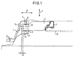
- the adjusting element 1 shown in FIG. 1 is designed as a hinge part. Instead of of a hinge part, another receiving part can also be used.
- the Adjustment element 1 is rotatable about a vertical axis 2 with the door box one Motor vehicle door connected.
- the setting element 1 is connected to a connecting piece 3 by that a connection with the door frame 4 of the motor vehicle door is established.
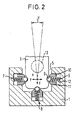
- the setting element 1 has a cup-shaped receptacle 5 in which three spring elements 6, 7 and 8 are provided.
- the first spring element 6 and the second spring element 7 are arranged opposite one another.
- the third spring element 8 ( Figure 2) is at right angles to the first spring element 6 and the second spring element 7 arranged. It is located in the middle between the spring elements 6 and 7.
- the spring elements 6 and 7 are arranged in the y direction, that is to say in the direction transverse to the longitudinal axis of the motor vehicle.
- the spring element 8 is arranged in the z direction, in the vertical direction, namely under the end of the connector 3.
- the x direction runs in the longitudinal direction of the vehicle.
- a tolerance wedge is provided that can be moved in the z direction is (not shown in detail in the drawing).
- the spring elements 6 and 7 are used for tolerance compensation in the y direction.
- the spring element 8 is used for tolerance compensation in the z direction.
- Each spring element 6, 7, 8 has a locking ball 9, which is in a corresponding Recess in the housing part 10 of the spring element rests.
- the housing part 10 is in a recess 11 of the adjusting element 1 is slidably mounted. It is pot-shaped designed, wherein the recess is on the side facing away from the ball and receives a spring assembly 12 which is supported on the bottom of the recess 11.
- the spring assembly 12 is the spring element in the direction of the connecting piece 3 preloaded.
- the spring elements 7 and 8 are constructed in a corresponding manner.
- a screw hole 13 is provided, which is in the x direction extends and that with a corresponding bore 14 in the adjusting element 1 is aligned.
- a screw bolt is inserted through the hole 14 and with the Screw hole 13 screwed (not shown in the drawing).
- the adjustment element ensures a perfect adjustment of the connecting piece 3 and thus the frame 4. Due to tolerances, the Position of the end of the connector 3 in the y direction and in the z direction deviate.
- the connector 3 is inserted into the cup-shaped receptacle 5. It is held there by the spring elements 6, 7, 8.
- the end of the connector 3 in the be brought into the correct position in which his screw hole 13 with the bore 14 of the Adjustment element is aligned. In this position, the screw connection between the connector and the adjusting element 1 are made.
- the pane of the motor vehicle door is provided with the reference number 15.
- the invention provides an adjusting element that is easy to pre-adjust allows. Manual readjustment is not necessary.
- the adjustment element enables continuous adjustment. It enables inexpensive installation.
Landscapes
- Engineering & Computer Science (AREA)
- Mechanical Engineering (AREA)
- Power-Operated Mechanisms For Wings (AREA)
- Window Of Vehicle (AREA)
Description
Claims (7)
- Einstellelement zum Justieren und Verbinden des Verbindungsstücks (3) eines Türrahmens (4) mit dem Türkasten einer Kraftfahrzeugtüre,
dadurch gekennzeichnet, daß das Einstellelement (1) mit dem Türkasten verbunden ist und eine topfförmige Aufnahme (5) besitzt, in der mindestens ein Federelement (6, 7, 8) vorgesehen ist,
wobei das Verbindungsstück (3) in die topfförmige Aufnahme (5) einführbar und in die korrekte Lage bringbar ist, in der es mit dem Einstellelement (1) verbindbar ist. - Einstellelement nach Anspruch 1, dadurch gekennzeichnet, daß zwei Federelemente (6, 7) vorgesehen sind, die vorzugsweise einander gegenüberliegend angeordnet sind.
- Einstellelement nach Anspruch 1 oder 2, dadurch gekennzeichnet, daß ein weiteres Federelement (8) vorgesehen ist, das vorzugsweise im Winkel, vorzugsweise in einem rechten Winkel, zu dem ersten Federelement (6, 7) angeordnet ist.
- Einstellelement nach einem der vorhergehenden Ansprüche, dadurch gekennzeichnet, daß das bzw. die Federelemente (6, 7, 8) mit Rastkugeln (9) versehen sind.
- Einstellelement nach einem der vorhergehenden Ansprüche, dadurch gekennzeichnet, daß das bzw die Federelemente (6, 7, 8) an einem Aufnahmeteil oder an einem Scharnierteil (1) vorgesehen sind.
- Kraftfahrzeugtüre, gekennzeichnet durch ein Einstellelement nach einem der Ansprüche 1 bis 5.
- Kraftfahrzeug, gekennzeichnet durch eine Kraftfahrzeugtüre nach Anspruch 6.
Applications Claiming Priority (4)
| Application Number | Priority Date | Filing Date | Title |
|---|---|---|---|
| DE10009857 | 2000-03-01 | ||
| DE10009857 | 2000-03-01 | ||
| DE10013867 | 2000-03-21 | ||
| DE10013867A DE10013867B4 (de) | 2000-03-01 | 2000-03-21 | Einstellelement für die Montage eines justierbaren Fensterrahmens in einem Türkasten einer Kraftfahrzeugtüre |
Publications (3)
| Publication Number | Publication Date |
|---|---|
| EP1129876A2 EP1129876A2 (de) | 2001-09-05 |
| EP1129876A3 EP1129876A3 (de) | 2002-07-17 |
| EP1129876B1 true EP1129876B1 (de) | 2004-10-27 |
Family
ID=26004614
Family Applications (1)
| Application Number | Title | Priority Date | Filing Date |
|---|---|---|---|
| EP20010104391 Expired - Lifetime EP1129876B1 (de) | 2000-03-01 | 2001-02-23 | Einstellelement zum Verbinden des Rahmens mit dem Türkasten einer Kraftfahrzeugtüre |
Country Status (1)
| Country | Link |
|---|---|
| EP (1) | EP1129876B1 (de) |
Family Cites Families (6)
| Publication number | Priority date | Publication date | Assignee | Title |
|---|---|---|---|---|
| DE3608506A1 (de) * | 1986-03-14 | 1987-11-19 | Daimler Benz Ag | Fahrzeugtuer mit einem einstellbaren tueraussenblatt |
| DE3718124C1 (de) * | 1987-05-29 | 1988-12-22 | Audi Ag | Kraftfahrzeugtuer,insbesondere fuer Personenkraftwagen |
| DE3943407A1 (de) * | 1989-12-30 | 1991-07-04 | Scharwaechter Gmbh Co Kg | Tuerfeststeller fuer kraftwagentueren |
| DE19608496A1 (de) * | 1996-03-05 | 1997-09-11 | Scharwaechter Gmbh Co Kg | Drehstab-Türfeststeller für Kraftwagentüren |
| DE29901413U1 (de) * | 1999-01-28 | 2000-01-05 | HYMER-LEICHTMETALLBAU GMBH & CO. KG, 88239 Wangen | Befestigungselement mit Ausgleich von Distanzen an Befestigungsflächen |
| DE10007454C2 (de) * | 2000-02-18 | 2003-01-16 | Dura Automotive Plettenberg | Toleranzausgleich-Element |
-
2001
- 2001-02-23 EP EP20010104391 patent/EP1129876B1/de not_active Expired - Lifetime
Also Published As
| Publication number | Publication date |
|---|---|
| EP1129876A2 (de) | 2001-09-05 |
| EP1129876A3 (de) | 2002-07-17 |
Similar Documents
| Publication | Publication Date | Title |
|---|---|---|
| DE3030519C2 (de) | Außenliegender Ziehgriff, insbesondere für Kraftfahrzeugtüren | |
| EP0685622B1 (de) | Verfahren zur Montage eines schwenkbeweglichen Fahrzeugteils und Scharnier zu dessen Realisierung | |
| DE112018000009T5 (de) | Längseinsteller für einen Fahrzeugsitz | |
| DE3605434C2 (de) | Befestigung für ein mit einem Türfeststeller baulich vereinigtes Türscharnier | |
| DE19956756A1 (de) | Einstellbarer Mitnehmer für einen Fensterheber einer rahmenlosen Fahrzeugtür | |
| DE102006053197B3 (de) | Kraftfahrzeugtürscharnier | |
| EP0960760B1 (de) | Klemmhalterung für eine Sichtscheibe eines Kraftfahrzeuges | |
| DE3539576C2 (de) | ||
| DE10232105B4 (de) | Vorrichtung zum automatischen Verschwenken einer Kraftfahrzeugtür | |
| WO2011006846A1 (de) | Mitnehmer zur anbindung einer fensterscheibe an einen fensterheber eines kraftfahrzeugs | |
| DE10013867B4 (de) | Einstellelement für die Montage eines justierbaren Fensterrahmens in einem Türkasten einer Kraftfahrzeugtüre | |
| DE102018105959B4 (de) | Montageanordnung eines Luftleitelements | |
| DE3243831C1 (de) | Lagerung für Scharnierarme von Flügeln, insbesondere von Viergelenkkoppelgetrieben zum schwenkbaren Anschlagen von Abdeckhauben | |
| EP3665038A1 (de) | Längseinsteller für einen fahrzeugsitz | |
| DE202022003194U1 (de) | Betätigungssystem mit modularer Fixierung | |
| DE19809449B4 (de) | Betätigungsvorrichtung für ein Kraftfahrzeug-Türschloß | |
| AT406407B (de) | Montagehalter | |
| DE19631941C2 (de) | Befestigung für eine Abdeckung | |
| EP1129876A2 (de) | Einstellelement zum Verbinden des Rahmens mit dem Türkasten einer Kraftfahrzeugtüre | |
| DE102006016018B3 (de) | Scharnier | |
| DE202005021007U1 (de) | Kraftfahrzeugtürscharnier | |
| EP1503018A2 (de) | Fahrzeug mit zumindest einer Fahrzeugklappe | |
| DE102009042633B4 (de) | Kraftfahrzeug mit Crashbox | |
| WO2018069234A1 (de) | Adapteranordnung, verfahren zu deren herstellung, baukastensystem für eine adapteranordnung, antriebsanordnung und verfahren zu deren herstellung sowie fahrzeugsitz | |
| DE19927507B4 (de) | Justierbares Schwenklager, insbesondere für eine Kraftfahrzeugtür |
Legal Events
| Date | Code | Title | Description |
|---|---|---|---|
| PUAI | Public reference made under article 153(3) epc to a published international application that has entered the european phase |
Free format text: ORIGINAL CODE: 0009012 |
|
| AK | Designated contracting states |
Kind code of ref document: A2 Designated state(s): AT BE CH CY DE DK ES FI FR GB GR IE IT LI LU MC NL PT SE TR |
|
| AX | Request for extension of the european patent |
Free format text: AL;LT;LV;MK;RO;SI |
|
| PUAL | Search report despatched |
Free format text: ORIGINAL CODE: 0009013 |
|
| AK | Designated contracting states |
Kind code of ref document: A3 Designated state(s): AT BE CH CY DE DK ES FI FR GB GR IE IT LI LU MC NL PT SE TR |
|
| AX | Request for extension of the european patent |
Free format text: AL;LT;LV;MK;RO;SI |
|
| RIC1 | Information provided on ipc code assigned before grant |
Free format text: 7B 60J 5/04 A, 7B 60J 5/02 B, 7B 60J 5/10 B |
|
| 17P | Request for examination filed |
Effective date: 20020920 |
|
| 17Q | First examination report despatched |
Effective date: 20021219 |
|
| AKX | Designation fees paid |
Designated state(s): DE FR GB IT |
|
| GRAP | Despatch of communication of intention to grant a patent |
Free format text: ORIGINAL CODE: EPIDOSNIGR1 |
|
| RTI1 | Title (correction) |
Free format text: ADJUSTING ELEMENT TO CONNECT A DOOR FRAME TO THE DOOR BOX OF A MOTOR VEHICLE |
|
| GRAS | Grant fee paid |
Free format text: ORIGINAL CODE: EPIDOSNIGR3 |
|
| GRAA | (expected) grant |
Free format text: ORIGINAL CODE: 0009210 |
|
| AK | Designated contracting states |
Kind code of ref document: B1 Designated state(s): DE FR GB IT |
|
| REG | Reference to a national code |
Ref country code: GB Ref legal event code: FG4D Free format text: NOT ENGLISH |
|
| REG | Reference to a national code |
Ref country code: IE Ref legal event code: FG4D Free format text: GERMAN |
|
| REF | Corresponds to: |
Ref document number: 50104263 Country of ref document: DE Date of ref document: 20041202 Kind code of ref document: P |
|
| GBT | Gb: translation of ep patent filed (gb section 77(6)(a)/1977) |
Effective date: 20050126 |
|
| REG | Reference to a national code |
Ref country code: IE Ref legal event code: FD4D |
|
| ET | Fr: translation filed | ||
| PLBE | No opposition filed within time limit |
Free format text: ORIGINAL CODE: 0009261 |
|
| STAA | Information on the status of an ep patent application or granted ep patent |
Free format text: STATUS: NO OPPOSITION FILED WITHIN TIME LIMIT |
|
| 26N | No opposition filed |
Effective date: 20050728 |
|
| PGFP | Annual fee paid to national office [announced via postgrant information from national office to epo] |
Ref country code: IT Payment date: 20060228 Year of fee payment: 6 |
|
| PG25 | Lapsed in a contracting state [announced via postgrant information from national office to epo] |
Ref country code: IT Free format text: LAPSE BECAUSE OF NON-PAYMENT OF DUE FEES Effective date: 20070223 |
|
| PGFP | Annual fee paid to national office [announced via postgrant information from national office to epo] |
Ref country code: FR Payment date: 20100519 Year of fee payment: 10 |
|
| PGFP | Annual fee paid to national office [announced via postgrant information from national office to epo] |
Ref country code: GB Payment date: 20100429 Year of fee payment: 10 |
|
| PGFP | Annual fee paid to national office [announced via postgrant information from national office to epo] |
Ref country code: DE Payment date: 20110225 Year of fee payment: 11 |
|
| GBPC | Gb: european patent ceased through non-payment of renewal fee |
Effective date: 20110223 |
|
| REG | Reference to a national code |
Ref country code: FR Ref legal event code: ST Effective date: 20111102 |
|
| PG25 | Lapsed in a contracting state [announced via postgrant information from national office to epo] |
Ref country code: FR Free format text: LAPSE BECAUSE OF NON-PAYMENT OF DUE FEES Effective date: 20110228 |
|
| PG25 | Lapsed in a contracting state [announced via postgrant information from national office to epo] |
Ref country code: GB Free format text: LAPSE BECAUSE OF NON-PAYMENT OF DUE FEES Effective date: 20110223 |
|
| REG | Reference to a national code |
Ref country code: DE Ref legal event code: R119 Ref document number: 50104263 Country of ref document: DE Effective date: 20120901 |
|
| PG25 | Lapsed in a contracting state [announced via postgrant information from national office to epo] |
Ref country code: DE Free format text: LAPSE BECAUSE OF NON-PAYMENT OF DUE FEES Effective date: 20120901 |