EP1129906A2 - Rétroviseur extérieur pour un véhicule - Google Patents
Rétroviseur extérieur pour un véhicule Download PDFInfo
- Publication number
- EP1129906A2 EP1129906A2 EP00121079A EP00121079A EP1129906A2 EP 1129906 A2 EP1129906 A2 EP 1129906A2 EP 00121079 A EP00121079 A EP 00121079A EP 00121079 A EP00121079 A EP 00121079A EP 1129906 A2 EP1129906 A2 EP 1129906A2
- Authority
- EP
- European Patent Office
- Prior art keywords
- mirror
- head
- height level
- mirror head
- travel
- Prior art date
- Legal status (The legal status is an assumption and is not a legal conclusion. Google has not performed a legal analysis and makes no representation as to the accuracy of the status listed.)
- Granted
Links
- 230000006835 compression Effects 0.000 claims description 15
- 238000007906 compression Methods 0.000 claims description 15
- 230000009471 action Effects 0.000 claims description 4
- 239000011521 glass Substances 0.000 claims description 3
- 230000007704 transition Effects 0.000 claims description 2
- 238000010586 diagram Methods 0.000 description 7
- 238000000034 method Methods 0.000 description 7
- 230000008569 process Effects 0.000 description 7
- 230000015572 biosynthetic process Effects 0.000 description 2
- 230000006378 damage Effects 0.000 description 2
- 238000005755 formation reaction Methods 0.000 description 2
- 230000009467 reduction Effects 0.000 description 2
- 230000000694 effects Effects 0.000 description 1
- 230000001771 impaired effect Effects 0.000 description 1
- 230000003993 interaction Effects 0.000 description 1
- 230000007257 malfunction Effects 0.000 description 1
- 230000002265 prevention Effects 0.000 description 1
- 230000000284 resting effect Effects 0.000 description 1
- 230000000717 retained effect Effects 0.000 description 1
- 238000009964 serging Methods 0.000 description 1
Images



Classifications
-
- B—PERFORMING OPERATIONS; TRANSPORTING
- B60—VEHICLES IN GENERAL
- B60R—VEHICLES, VEHICLE FITTINGS, OR VEHICLE PARTS, NOT OTHERWISE PROVIDED FOR
- B60R1/00—Optical viewing arrangements; Real-time viewing arrangements for drivers or passengers using optical image capturing systems, e.g. cameras or video systems specially adapted for use in or on vehicles
- B60R1/02—Rear-view mirror arrangements
- B60R1/06—Rear-view mirror arrangements mounted on vehicle exterior
- B60R1/062—Rear-view mirror arrangements mounted on vehicle exterior with remote control for adjusting position
- B60R1/07—Rear-view mirror arrangements mounted on vehicle exterior with remote control for adjusting position by electrically powered actuators
- B60R1/074—Rear-view mirror arrangements mounted on vehicle exterior with remote control for adjusting position by electrically powered actuators for retracting the mirror arrangements to a non-use position alongside the vehicle
Definitions
- the invention relates to an exterior rear view mirror according to the preamble of Claim 1.
- Such an external rearview mirror is known from DE-OS 198 33 672 A1.
- a motorized adjustment of the Mirror head between the driving position and the parking position as well as a manual Can be operated in or against the direction of travel.
- the gearwheel With every manual operation in and against the direction of travel the gearwheel is blocked when the gearbox is blocked forced against its locking position in the mirror base by disengaging the locking means to leave the force of the compression spring. If this manual operation occurs very often, then this can lead to wear effects on the locking means, causing the Resting function is impaired. This can result in the mirror head not can be held more vibration-free on the mirror base.
- the exterior rear view mirror with motor drive behaves like the previously known exterior rear view mirror.
- the locking means of the locking ring which are connected to the gearwheel snap out of the locking means of the mirror base because the locking means are shaped so that they can be unlocked in this direction, the frictional force being higher than that Disengaging force in the direction of travel.
- the guideway limiter between the mirror head and the mirror base which cannot be overcome by a motor, is overcome. The folded mirror head can then be returned to the driving position by motor.
- the latching means of the latching ring which is frictionally connected to the gear do not disengage from the latching means of the mirror base, because the latching means are shaped such that they block in this direction. For this reason, the frictional force between the gearwheel and the locking ring can be overcome by the external force until the travel or folding path limiter is reached.
- the mirror can then be returned to the driving position by motor, without a synchronization process having to be initiated between the latching means on the latching ring and the latching means on the mirror base, because the assignment between the latching ring and mirror base is retained even in this forced process. This reduces the time required for the reset process and also simplifies the control that may be available for this.
- the locking means are in the form of locking cams and recesses are formed, the flanks of which are inclined differently. Due to the different inclination of the flanks, disengagement is only possible in one direction possible. It is irrelevant whether the locking recesses or the locking cams in Locking ring or in the mirror foot are arranged.
- the mirror head in relation to the Mirror base can occupy several height levels, being at all height levels and in all angular positions of the mirror head friction between the Gear and the locking ring, which is maintained by the compression spring.
- the non-positive connection between the locking ring and the gear would be interrupted when parts of the mirror head open in the disengaged state Parts of the mirror base would sit on. To prevent this from happening in this Position at least a small gap between mirror head and mirror base in Swivel axis direction must be present.
- the guideway limiter between the mirror head and mirror base must be overcome and the mirror head is two height levels (H, L) in relation to the mirror base can take.
- H, L height levels
- To move from the low level (L) to the medium level (H) must arrive at a particularly advantageous embodiment of the invention third height level (Z) to be overcome.
- This third height level (Z) should be there not to be taken permanently, but only when exposed to an external force can be reached for a short time and immediately left.
- the third height level (Z) should can not be reached by motor from the height level (L) or from the height level (H) his.
- the second height level (H) will only be in forward Direction of travel folded down mirror positions (K) is possible, so is a Wear of the locking means on the mirror base only when folding down less frequently external force possible in the direction of travel.
- the third height level (Z) is only reached for a short time, it is necessary that the third height level (Z) only between the driving position (F) and a mirror position (K) folded forward in the direction of travel is possible.
- This position is the greatest moment necessary for the To be able to fold down mirrors at all, if this is applied, it is hardly possible reduce it quickly enough so that the third height level (Z) is maintained.
- the projecting projection on the locking ring or on the mirror base so that no stable positioning on the third Height level is possible.
- Motor adjustment is still possible, however, incorrect operation, such as mentioned lead to malfunction.
- the transition between the middle height level (H) and the third height level (Z) is preferably designed as a stop, the stop being in relation to the swivel plane inclined surface is formed. This makes it possible Mirror also by hand overcoming the third level (Z) in the Bring driving position back. However, since the third level (Z) is not motorized the inclination of the surface of the stop is appropriate designed.
- the friction surface between the Gear and the locking ring conical.
- the frictional force between the gear and the locking ring is greatly increased.
- the frictional force can be adapted to the requirements.
- An advantageous development of the invention is characterized in that a stopper is provided on the mirror head and a counter stopper is provided on the mirror base, the stopper in the driving position (F) or in the vicinity of the driving position (F) can be struck on the counter stopper in the pivoting direction when the disengageable ones Latching means are in a disengaged state and the stopper can not be struck with the counter stopper in any pivoting position when the disengageable locking means are in the engaged state.
- This measure results in a particularly rapid synchronization of the locking means on the locking ring with the locking means on the mirror base, and it is also not necessary to move the mirror to a stop in the parking position in order to be able to carry out the synchronization. This saves considerable distances and times.
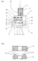
- Fig. 1 shows a schematic diagram of a drive 6 for a motor vehicle exterior rear view mirror in a driving position, with a mirror base 3, a mirror head 4, a locking ring 17, a gear 14, a ball bearing and a compression spring 12 which exert a force F on the around a pivot axis 7 superimposed components (mirror base 3, locking ring 17, gear 14, ball bearing and mirror head 4) exercises.
- the locking ring 17 is over Locking means 13 with the mirror base 3 in a form-fitting manner and via friction surfaces 16 with the Gear 14 frictionally connected.
- the mirror head 4 lies over the stop means 9 and counter stop means 10 on the mirror base 3.
- An articulated tube 28 is connected to the Mirror base 3 in one piece and part of a swivel joint 11
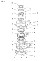
- Fig. 2 shows a schematic diagram of the drive in a second position in the Locking ring 17 disengaged from the locking means 13 and the mirror head 4 opposite the mirror base 3 is raised.
- the mirror head 4 is here on a middle level.
- the locking means 13 consist of locking cams 21 in the mirror base 3 and Locking recesses 20 in the locking ring 17.
- the locking recesses 20 are with differently inclined flanks 24, 25, the first flank 24 is oriented at right angles or approximately at right angles to the direction of adjustment and the second flank 25 is inclined to the direction of adjustment, so that a disengagement upon action a sufficiently large force is possible.
- This second flank 25 projecting projection 26 connects to this second flank 25 projecting projection 26, the width of which is small in the pivoting direction and the on the side opposite the recess 20 by a stop serving inclined surface 27 is limited.
- the angle of inclination of the surface 27 is there chosen so that it can only be counteracted by an external force, but not by a motor the compression spring 12 can be overcome.
- the projecting projection 26 serves as Prevention of incorrect operation, which could lead to the Compression spring 12 no more force on the friction surface 16 between the gear 14 and the locking ring 17 would exercise. In such a situation, the rearview mirror would be no longer drivable by motor.
- Fig. 3 shows the friction surface 16 between the gear 14 and the locking ring 17 as Ring cone. By changing the cone angle, the frictional force on the desired value can be set.
- Fig. 4 shows an exploded view of the drive with the mirror base 3, the Articulated tube 28, the stops 9, the locking cams 21, a folding path limiter 15, a housing 33, the locking ring 17 with the locking recesses 20 and protruding formations 26, the gear 14, a reduction gear 34, which consists of a two-stage worm gear and not one Small electric motor shown is driven, a ball bearing 32, the mirror head 4, the counter stops 10, discs 35, the compression spring 12 and the toothed disc 36.
- the compression spring 12 is supported on the one hand via a disk 35 and the toothed disc 36 on the articulated tube 28 and thus on the mirror base 3 and on the other hand acts on the second disc 35, the mirror head 4, the bearing 32, the gear 14 and the locking ring 17 and thus ensures a defined frictional force the friction surface 16 and a secure hold of the locking ring 17 on the mirror base 3.
- Fig. 6 shows another somewhat simplified exploded view of parts of the Drive 6, from which the interaction of the folding path limiter 15 on the mirror head 4 and on the mirror base 3 becomes clear.
- FIG. 7 shows the exterior rearview mirror 1 which can be pivoted about the pivot axis 7 Motor vehicle 2 with the mirror glass 5, the mirror base 3, and the drive 6, the over the compression spring 12 is held on the mirror base 3 under the action of force.
- the possible positions of the mirror head 4 are shown in Fig. 8. Becomes motor the mirror head in normal operation only between the driving position F and Park position P adjusted. If it comes through from outside on the mirror head 4 impact to a forced folding of the mirror head 4 in Direction of travel (position K), then there is both a manual reset and one motor reset possible. In the case mentioned, the mirror head 4 raised relative to the mirror base 3 and the locking connection between the Locking ring 17 and the mirror base 3 canceled. When resetting the motor is usually a synchronization process necessary to the locking means of the locking ring and align the mirror base again. With a forced one The mirror head 4 will not fold down against the direction of travel (direction P) raised because the flanks of the locking means 13 are too steep in this direction to be overcome.
- FIG. 9 An advantageous development of the exterior rearview mirror according to the invention (Fig. 9) now allows the unnecessary travel paths when Waive synchronization process. To achieve this are only minor Make changes to the existing exterior rearview mirror. It has to be for that be ensured that there is a stop near the driving position F, which is only in a lifted position of the mirror head 4 can act around the mirror head to be able to drive into the parking position (P). 9 is a simple one Realization possibility shown. A stopper 30, preferably integral with the housing 33 of the mirror head 4, has no possibility in normal operation a mirror stop fixed counter stop 31 come into contact. Is the mirror head 4 but folded forward in the direction of travel (K) and the mirror head 4 with respect to the mirror base 3 is raised a stop between the stopper 30 and Counterstop 31 possible.
- the position of the stopper 30 and counter stop 31 is so chosen so that the synchronization can take place in driving position (F). Basically however, any position can be selected for this.
- the counter stop 31 on the mirror base side is only a disk for Holding down the compression spring shaped into a pot 38, on the edge of the pot Counter stoppers 31 are arranged.
- the stopper 30 or counter stopper 31 can be at any point on the Mirror head 4 or the mirror base 3 may be mounted, also a radial arrangement with respect to the pivot axis 7 is possible.
- FIG. 12 shows the essential possible positions of the locking ring 17th opposite the mirror base 3 and next to the associated positions between Mirror foot 3 and mirror head 4.
- the locked position is shown in the the distance (L) between the locking ring 17 and the mirror base 3 or Mirror head 4 and the mirror base 3 is the lowest.
- Fig. 12 one Intermediate position shown, which only during the forced folding movement in Direction of travel is reached and immediately left again. In this position the Distance between mirror base 3 and the locking ring 17 or the mirror head 4 its greatest value (Z).
- the position immediately taken up is shown in FIG. 13 shown.
- the distance between the mirror base 3 and the locking ring 17 and the The mirror head 4 lies in a middle area (H) between the positions (L) and Z).
- the sloping surface 27 of the projecting surface serving as a stop Forming 26 prevents incorrect operation, in which the mirror head 4 is motorized is driven further in the direction of travel so that synchronization can take place, because this would lead to the mirror head 4 sitting on the mirror base 3 and thus disengaging the friction clutch.
- the mirror head would be motorized then no longer resettable.
- the inclined surface 27 thus blocks the Drive. This can be recognized electronically or by the operator and the drive thus be reversed.
- the surface 27 is chamfered to the mirror head 4 as well to be able to bring it back to its original position by hand.
Landscapes
- Engineering & Computer Science (AREA)
- Multimedia (AREA)
- Mechanical Engineering (AREA)
- Rear-View Mirror Devices That Are Mounted On The Exterior Of The Vehicle (AREA)
Applications Claiming Priority (2)
| Application Number | Priority Date | Filing Date | Title |
|---|---|---|---|
| DE10009579A DE10009579B4 (de) | 2000-02-29 | 2000-02-29 | Außenrückblickspiegel für ein Kraftfahrzeug |
| DE10009579 | 2000-02-29 |
Publications (3)
| Publication Number | Publication Date |
|---|---|
| EP1129906A2 true EP1129906A2 (fr) | 2001-09-05 |
| EP1129906A3 EP1129906A3 (fr) | 2003-09-24 |
| EP1129906B1 EP1129906B1 (fr) | 2004-08-04 |
Family
ID=7632860
Family Applications (1)
| Application Number | Title | Priority Date | Filing Date |
|---|---|---|---|
| EP00121079A Expired - Lifetime EP1129906B1 (fr) | 2000-02-29 | 2000-09-28 | Rétroviseur extérieur pour un véhicule |
Country Status (3)
| Country | Link |
|---|---|
| EP (1) | EP1129906B1 (fr) |
| AT (1) | ATE272516T1 (fr) |
| DE (1) | DE10009579B4 (fr) |
Cited By (15)
| Publication number | Priority date | Publication date | Assignee | Title |
|---|---|---|---|---|
| GB2372025A (en) * | 2000-12-20 | 2002-08-14 | Tokai Rika Co Ltd | Manually foldable door mirror |
| NL1023227C2 (nl) * | 2003-04-18 | 2004-10-19 | Iku Holding Montfoort Bv | Buitenspiegeleenheid. |
| NL1025433C2 (nl) * | 2004-02-06 | 2005-08-09 | Iku Holding Montfoort Bv | Scharnieractuator en werkwijze voor het ten opzichte van elkaar verstellen van twee delen van een scharnieractuator. |
| NL1025437C2 (nl) * | 2004-02-06 | 2005-08-09 | Iku Holding Montfoort Bv | Scharnieractuator. |
| NL1025434C2 (nl) * | 2004-02-06 | 2005-08-09 | Iku Holding Montfoort Bv | Scharnieractuator en werkwijze voor het ten opzichte van elkaar verstellen van twee delen van een scharnieractuator. |
| WO2005075249A1 (fr) * | 2004-02-06 | 2005-08-18 | Eaton Automotive B.V. | Actionneur articule et procede de reglage des deux parties d'un actionneur articule l'une par rapport a l'autre |
| NL1026002C2 (nl) * | 2004-04-22 | 2005-10-25 | Iku Holding Montfoort Bv | Scharnieractuator, in het bijzonder voor een buitenspiegeleenheid. |
| NL1026014C2 (nl) * | 2004-04-23 | 2005-10-25 | Iku Holding Montfoort Bv | Scharnieractuator alsmede werkwijze voor het ten opzichte van elkaar verstellen van twee delen van een scharnieractuator. |
| CN105034957A (zh) * | 2015-08-22 | 2015-11-11 | 宁波精成车业有限公司 | 用于汽车外后视镜的电动折叠装置 |
| CN109681550A (zh) * | 2019-02-01 | 2019-04-26 | 上海普英特高层设备股份有限公司 | 制动锁止机构 |
| CN111263711A (zh) * | 2017-10-20 | 2020-06-09 | 荷兰反光镜控制器国际有限公司 | 特别是用于机动车辆的外部视觉单元的紧固构造 |
| CN112977260A (zh) * | 2021-03-31 | 2021-06-18 | 安徽江淮汽车集团股份有限公司 | 外后视镜折叠装置、外后视镜及汽车 |
| CN113276778A (zh) * | 2020-02-20 | 2021-08-20 | 麦格纳镜片美国有限公司 | 用于外部镜的电动折叠致动器 |
| CN113561900A (zh) * | 2021-08-27 | 2021-10-29 | 启东捌友精密汽车部件有限公司 | 一种抗震可拆卸汽车后视镜支架 |
| CN119278148A (zh) * | 2022-08-24 | 2025-01-07 | 宝马股份公司 | 用于安装车辆的车内后视镜的底座、镜脚和安装组件 |
Families Citing this family (1)
| Publication number | Priority date | Publication date | Assignee | Title |
|---|---|---|---|---|
| JP5488429B2 (ja) * | 2010-11-26 | 2014-05-14 | 市光工業株式会社 | 車両用アウトサイドミラー装置 |
Citations (1)
| Publication number | Priority date | Publication date | Assignee | Title |
|---|---|---|---|---|
| DE19833672A1 (de) | 1997-07-30 | 1999-05-06 | Buhler Motor Gmbh | Außenrückblickspiegel für Kraftfahrzeuge |
Family Cites Families (2)
| Publication number | Priority date | Publication date | Assignee | Title |
|---|---|---|---|---|
| NL9202266A (nl) * | 1992-12-24 | 1994-07-18 | Iku Holding Montfoort Bv | Spiegelinklapmechanisme, en voertuig voorzien van een dergelijk spiegelinklapmechanisme. |
| NL1003144C2 (nl) * | 1996-05-15 | 1997-11-18 | Iku Holding Montfoort Bv | Elektrisch bedienbare scharnieractuator, en buitenspiegel met elektrisch bedienbaar scharniermechanisme. |
-
2000
- 2000-02-29 DE DE10009579A patent/DE10009579B4/de not_active Expired - Fee Related
- 2000-09-28 EP EP00121079A patent/EP1129906B1/fr not_active Expired - Lifetime
- 2000-09-28 AT AT00121079T patent/ATE272516T1/de not_active IP Right Cessation
Patent Citations (1)
| Publication number | Priority date | Publication date | Assignee | Title |
|---|---|---|---|---|
| DE19833672A1 (de) | 1997-07-30 | 1999-05-06 | Buhler Motor Gmbh | Außenrückblickspiegel für Kraftfahrzeuge |
Cited By (26)
| Publication number | Priority date | Publication date | Assignee | Title |
|---|---|---|---|---|
| US6637898B2 (en) | 2000-12-20 | 2003-10-28 | Kabushiki Kaisha Tokai Rika Denki Seisakusho | Manually foldable door mirror |
| GB2372025B (en) * | 2000-12-20 | 2004-04-07 | Tokai Rika Co Ltd | Manually foldable door mirror |
| GB2372025A (en) * | 2000-12-20 | 2002-08-14 | Tokai Rika Co Ltd | Manually foldable door mirror |
| CN100371187C (zh) * | 2003-04-18 | 2008-02-27 | 伊顿汽车有限公司 | 翼子板后视镜装置 |
| NL1023227C2 (nl) * | 2003-04-18 | 2004-10-19 | Iku Holding Montfoort Bv | Buitenspiegeleenheid. |
| WO2004091974A1 (fr) * | 2003-04-18 | 2004-10-28 | Eaton Automotive B.V. | Retroviseur |
| US7628499B2 (en) | 2003-04-18 | 2009-12-08 | Mci (Mirror Controls International) Netherlands B.V. | Wing mirror unit |
| NL1025437C2 (nl) * | 2004-02-06 | 2005-08-09 | Iku Holding Montfoort Bv | Scharnieractuator. |
| CN100564105C (zh) * | 2004-02-06 | 2009-12-02 | 伊顿汽车有限公司 | 铰接致动器 |
| WO2005075250A1 (fr) * | 2004-02-06 | 2005-08-18 | Eaton Automotive B.V. | Actionneur articule |
| NL1025433C2 (nl) * | 2004-02-06 | 2005-08-09 | Iku Holding Montfoort Bv | Scharnieractuator en werkwijze voor het ten opzichte van elkaar verstellen van twee delen van een scharnieractuator. |
| WO2005075249A1 (fr) * | 2004-02-06 | 2005-08-18 | Eaton Automotive B.V. | Actionneur articule et procede de reglage des deux parties d'un actionneur articule l'une par rapport a l'autre |
| NL1025434C2 (nl) * | 2004-02-06 | 2005-08-09 | Iku Holding Montfoort Bv | Scharnieractuator en werkwijze voor het ten opzichte van elkaar verstellen van twee delen van een scharnieractuator. |
| US7374299B2 (en) | 2004-02-06 | 2008-05-20 | Mci (Mirror Controls International) Netherlands B.V. | Hinge actuator |
| US7547855B2 (en) | 2004-02-06 | 2009-06-16 | Mci (Mirror Controls International) Netherlands B.V. | Hinge actuator and method for adjusting two parts of a hinge actuator relative to each other |
| CN100528637C (zh) * | 2004-02-06 | 2009-08-19 | 伊顿汽车有限公司 | 铰接致动器以及调节铰接致动器的两部件间相对位置的方法 |
| NL1026002C2 (nl) * | 2004-04-22 | 2005-10-25 | Iku Holding Montfoort Bv | Scharnieractuator, in het bijzonder voor een buitenspiegeleenheid. |
| NL1026014C2 (nl) * | 2004-04-23 | 2005-10-25 | Iku Holding Montfoort Bv | Scharnieractuator alsmede werkwijze voor het ten opzichte van elkaar verstellen van twee delen van een scharnieractuator. |
| CN105034957A (zh) * | 2015-08-22 | 2015-11-11 | 宁波精成车业有限公司 | 用于汽车外后视镜的电动折叠装置 |
| CN111263711A (zh) * | 2017-10-20 | 2020-06-09 | 荷兰反光镜控制器国际有限公司 | 特别是用于机动车辆的外部视觉单元的紧固构造 |
| CN111263711B (zh) * | 2017-10-20 | 2023-10-13 | 荷兰反光镜控制器国际有限公司 | 特别是用于机动车辆的外部视觉单元的紧固构造 |
| CN109681550A (zh) * | 2019-02-01 | 2019-04-26 | 上海普英特高层设备股份有限公司 | 制动锁止机构 |
| CN113276778A (zh) * | 2020-02-20 | 2021-08-20 | 麦格纳镜片美国有限公司 | 用于外部镜的电动折叠致动器 |
| CN112977260A (zh) * | 2021-03-31 | 2021-06-18 | 安徽江淮汽车集团股份有限公司 | 外后视镜折叠装置、外后视镜及汽车 |
| CN113561900A (zh) * | 2021-08-27 | 2021-10-29 | 启东捌友精密汽车部件有限公司 | 一种抗震可拆卸汽车后视镜支架 |
| CN119278148A (zh) * | 2022-08-24 | 2025-01-07 | 宝马股份公司 | 用于安装车辆的车内后视镜的底座、镜脚和安装组件 |
Also Published As
| Publication number | Publication date |
|---|---|
| DE10009579A1 (de) | 2001-09-20 |
| DE10009579B4 (de) | 2006-02-23 |
| EP1129906B1 (fr) | 2004-08-04 |
| EP1129906A3 (fr) | 2003-09-24 |
| ATE272516T1 (de) | 2004-08-15 |
Similar Documents
| Publication | Publication Date | Title |
|---|---|---|
| EP1129907B1 (fr) | Rétroviseur extérieur pour véhicules | |
| EP1129906B1 (fr) | Rétroviseur extérieur pour un véhicule | |
| DE2101915C3 (de) | Verriegelbares Gelenk | |
| EP1202870B9 (fr) | Mecanisme de reglage pour sieges dotes d'un dossier a inclinaison reglable, en particulier pour sieges de vehicules | |
| DE3625691C2 (fr) | ||
| DE3102402C2 (fr) | ||
| EP0960765B1 (fr) | Mécanisme de réglage | |
| EP1530523B1 (fr) | Accoudoir | |
| DE10017013A1 (de) | Anhängekupplung | |
| EP1451035B1 (fr) | Repose-bras | |
| DE10320328A1 (de) | Untersetzungsgetriebe für eine Verstellvorrichtung eines Kraftfahrzeugsitzes | |
| DE4022840C1 (en) | Car seat arm rest - has latching lever pivoted under spring-load with teeth on latching plate and can operate lever | |
| AT410778B (de) | Verstelleinrichtung für eine lenkwelle | |
| EP1128979B1 (fr) | Entrainement de dispositif de reglage de la hauteur pour un siege de vehicule | |
| DE19527374C2 (de) | Taumelbeschlag für Fahrzeugsitze, insbesondere Kraftfahrzeugsitze | |
| DE19831205C2 (de) | Stufenloser manueller Antrieb | |
| DE4023375C2 (fr) | ||
| WO2020148198A1 (fr) | Colonne de direction pour un véhicule automobile | |
| DE3509855C2 (fr) | ||
| DE3819597C2 (de) | Bei Einlegen des Rückwärtsganges schwenkbarer Außenspiegel | |
| DE3608828C2 (fr) | ||
| DE19952633C1 (de) | Beidseitig wirkender Antrieb für Verstellvorrichtungen in Kraftfahrzeugen | |
| DE19831442A1 (de) | Getriebe für Sitzverstelleinrichtungen in Kraftfahrzeugen | |
| DE102006033137A1 (de) | Fahrzeugsitz mit verstellbarer Kopfstütze | |
| DE69802850T2 (de) | Kegelrad-Winkelgetriebe mit einem Zahnradpaar mit auswechselbarem Übersetzungsverhältnis |
Legal Events
| Date | Code | Title | Description |
|---|---|---|---|
| PUAI | Public reference made under article 153(3) epc to a published international application that has entered the european phase |
Free format text: ORIGINAL CODE: 0009012 |
|
| AK | Designated contracting states |
Kind code of ref document: A2 Designated state(s): AT BE CH CY DE DK ES FI FR GB GR IE IT LI LU MC NL PT SE |
|
| AX | Request for extension of the european patent |
Free format text: AL;LT;LV;MK;RO;SI |
|
| PUAL | Search report despatched |
Free format text: ORIGINAL CODE: 0009013 |
|
| AK | Designated contracting states |
Kind code of ref document: A3 Designated state(s): AT BE CH CY DE DK ES FI FR GB GR IE IT LI LU MC NL PT SE |
|
| AX | Request for extension of the european patent |
Extension state: AL LT LV MK RO SI |
|
| RIC1 | Information provided on ipc code assigned before grant |
Ipc: 7F 16D 7/04 B Ipc: 7B 60R 1/074 A |
|
| 17P | Request for examination filed |
Effective date: 20031128 |
|
| GRAP | Despatch of communication of intention to grant a patent |
Free format text: ORIGINAL CODE: EPIDOSNIGR1 |
|
| GRAS | Grant fee paid |
Free format text: ORIGINAL CODE: EPIDOSNIGR3 |
|
| AKX | Designation fees paid |
Designated state(s): AT ES FR GB IT NL |
|
| GRAA | (expected) grant |
Free format text: ORIGINAL CODE: 0009210 |
|
| REG | Reference to a national code |
Ref country code: DE Ref legal event code: 8566 |
|
| AK | Designated contracting states |
Kind code of ref document: B1 Designated state(s): AT ES FR GB IT NL |
|
| PG25 | Lapsed in a contracting state [announced via postgrant information from national office to epo] |
Ref country code: NL Free format text: LAPSE BECAUSE OF FAILURE TO SUBMIT A TRANSLATION OF THE DESCRIPTION OR TO PAY THE FEE WITHIN THE PRESCRIBED TIME-LIMIT Effective date: 20040804 Ref country code: IT Free format text: LAPSE BECAUSE OF FAILURE TO SUBMIT A TRANSLATION OF THE DESCRIPTION OR TO PAY THE FEE WITHIN THE PRESCRIBED TIME-LIMIT;WARNING: LAPSES OF ITALIAN PATENTS WITH EFFECTIVE DATE BEFORE 2007 MAY HAVE OCCURRED AT ANY TIME BEFORE 2007. THE CORRECT EFFECTIVE DATE MAY BE DIFFERENT FROM THE ONE RECORDED. Effective date: 20040804 Ref country code: GB Free format text: LAPSE BECAUSE OF FAILURE TO SUBMIT A TRANSLATION OF THE DESCRIPTION OR TO PAY THE FEE WITHIN THE PRESCRIBED TIME-LIMIT Effective date: 20040804 Ref country code: FR Free format text: LAPSE BECAUSE OF FAILURE TO SUBMIT A TRANSLATION OF THE DESCRIPTION OR TO PAY THE FEE WITHIN THE PRESCRIBED TIME-LIMIT Effective date: 20040804 |
|
| REG | Reference to a national code |
Ref country code: GB Ref legal event code: FG4D Free format text: NOT ENGLISH |
|
| REG | Reference to a national code |
Ref country code: IE Ref legal event code: FG4D Free format text: GERMAN |
|
| PG25 | Lapsed in a contracting state [announced via postgrant information from national office to epo] |
Ref country code: AT Free format text: LAPSE BECAUSE OF NON-PAYMENT OF DUE FEES Effective date: 20040928 |
|
| PG25 | Lapsed in a contracting state [announced via postgrant information from national office to epo] |
Ref country code: ES Free format text: LAPSE BECAUSE OF FAILURE TO SUBMIT A TRANSLATION OF THE DESCRIPTION OR TO PAY THE FEE WITHIN THE PRESCRIBED TIME-LIMIT Effective date: 20041115 |
|
| NLV1 | Nl: lapsed or annulled due to failure to fulfill the requirements of art. 29p and 29m of the patents act | ||
| GBV | Gb: ep patent (uk) treated as always having been void in accordance with gb section 77(7)/1977 [no translation filed] |
Effective date: 20040804 |
|
| REG | Reference to a national code |
Ref country code: IE Ref legal event code: FD4D |
|
| PLBE | No opposition filed within time limit |
Free format text: ORIGINAL CODE: 0009261 |
|
| STAA | Information on the status of an ep patent application or granted ep patent |
Free format text: STATUS: NO OPPOSITION FILED WITHIN TIME LIMIT |
|
| 26N | No opposition filed |
Effective date: 20050506 |
|
| EN | Fr: translation not filed |