EP1129914A2 - Dispositif de nettoyage pour phare de voiture - Google Patents
Dispositif de nettoyage pour phare de voiture Download PDFInfo
- Publication number
- EP1129914A2 EP1129914A2 EP01103619A EP01103619A EP1129914A2 EP 1129914 A2 EP1129914 A2 EP 1129914A2 EP 01103619 A EP01103619 A EP 01103619A EP 01103619 A EP01103619 A EP 01103619A EP 1129914 A2 EP1129914 A2 EP 1129914A2
- Authority
- EP
- European Patent Office
- Prior art keywords
- closure member
- cleaning device
- opening
- cleaning
- open position
- Prior art date
- Legal status (The legal status is an assumption and is not a legal conclusion. Google has not performed a legal analysis and makes no representation as to the accuracy of the status listed.)
- Withdrawn
Links
- 238000004140 cleaning Methods 0.000 title claims abstract description 57
- 239000007788 liquid Substances 0.000 claims description 3
- 238000000034 method Methods 0.000 description 7
- 239000007921 spray Substances 0.000 description 4
- 238000011109 contamination Methods 0.000 description 2
- 238000005507 spraying Methods 0.000 description 2
- 230000001960 triggered effect Effects 0.000 description 2
- XLYOFNOQVPJJNP-UHFFFAOYSA-N water Substances O XLYOFNOQVPJJNP-UHFFFAOYSA-N 0.000 description 2
- 230000009286 beneficial effect Effects 0.000 description 1
- 239000012459 cleaning agent Substances 0.000 description 1
- 238000010276 construction Methods 0.000 description 1
- 238000005260 corrosion Methods 0.000 description 1
- 230000007797 corrosion Effects 0.000 description 1
- 238000009434 installation Methods 0.000 description 1
- 238000005406 washing Methods 0.000 description 1
Images

Classifications
-
- B—PERFORMING OPERATIONS; TRANSPORTING
- B60—VEHICLES IN GENERAL
- B60S—SERVICING, CLEANING, REPAIRING, SUPPORTING, LIFTING, OR MANOEUVRING OF VEHICLES, NOT OTHERWISE PROVIDED FOR
- B60S1/00—Cleaning of vehicles
- B60S1/02—Cleaning windscreens, windows or optical devices
- B60S1/46—Cleaning windscreens, windows or optical devices using liquid; Windscreen washers
- B60S1/48—Liquid supply therefor
- B60S1/52—Arrangement of nozzles; Liquid spreading means
- B60S1/522—Arrangement of nozzles; Liquid spreading means moving liquid spreading means, e.g. arranged in wiper arms
- B60S1/528—Arrangement of nozzles; Liquid spreading means moving liquid spreading means, e.g. arranged in wiper arms the spreading means being moved between a rest position and a working position
Definitions
- the opening In the park position of the Cleaning element, the opening is closed, so that it is behind the Closure member located cleaning element is protected from contamination and Wind noise can be avoided. Furthermore, it has already been proposed a window cleaning process with successive steps Electromechanically controlled to run automatically, and also already has been proposed to clean the two front headlights one Motor vehicle not to run on one side but one after the other, what by an associated electrical or electronic control device also automatically is controlled.
- the respective cleaning process can be done by manually operating a Actuator are initiated, the individual steps of The cleaning process can be automatically controlled in succession, namely opening of the flap-shaped closure member, moving the cleaning element into it Functional position, execution of the cleaning process over a certain time, e.g. B.
- Such a window cleaning layer has the disadvantage that the arbitrary opening the closure member is problematic. It is possible, manually or by means of a Tool, e.g. B. a screwdriver, in the circumferential gap of the closure member intervene, however, there is a risk of damage to the paintwork and also this is contrary to the existing requirement, the circumferential gap as small as possible to train.
- a Tool e.g. B. a screwdriver
- the invention has for its object a cleaning system of the present type To be designed so that a handling-friendly opening of the closure member and access to the opening is possible.
- the embodiment according to claim 1 not only enables one easy and user-friendly opening of the closure member but also access to or through the opening so that it is used as an access opening can be, e.g. B. to use the space behind the access opening, e.g. B. to check or a service on parts or devices arranged therein perform.
- This can be, for. B. an adjustment device for one Headlights and / or act as a reservoir for a cleaning liquid.
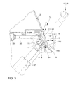
- one is designated in its entirety by 1a Cleaning device for cleaning the translucent pane of a front headlight 2 in combination with one in its entirety designated 1b Adjustment device for the headlight 2 arranged.
- the cleaning device 1a is also suitable for a non-adjustable headlight 2 or for Headlights of a different design
- the setting device 1b serves the purpose of Headlights 2 adjust or adjust, which is preferably a Basic attitude, i.e. to make a setting before the commissioning of the associated vehicle 3 and then to be carried out at greater intervals, so that existing dimensional tolerances of the body with such a setting are taken into account.
- the adjusting device 1b is located in the front area of the Vehicle 3. However, it can at least partially, especially with a one or a plurality of adjusting members 4 supporting base part 6, also in another area of the Vehicle 3 or its body 7 to be accessible.
- the main parts of the adjusting device 1a are the base part 6, which is the at least one Adjusting element 4 carries one or more connecting elements 8, each of which the associated Connect the setting member 4 to the adjustable headlight 2, an access opening 9, which enables manual access to the one or more setting members 4, and a Locking member 11 for the access opening 9.
- This opening and opening can be closed depending on the arrangement of the access opening 9 in Area of the body 7 at least the adjusting member 4 or the base part 6 in front Contamination, especially while the vehicle 3 is moving, and / or before Arrange a viewer's gaze protected or concealed.
- the setting member 4 or the associated parts of the setting device 1a protected against pollution and resulting corrosion, which the Function improved and the lifespan is extended.
- it is Adjustment element 4 at least when it is not in use, before the eye of a Observer arranged concealed, which makes the appearance of the vehicle 3 and its Shape and flow behavior can be improved.
- the at least one connecting link 8 is of elongated design, so that the Base part 6 with the connector 8 in a distance from the headlight 2 and easy to use convenient position can be arranged. It can also be of flexible or pliable construction. This makes it possible if in the direct distance between the base part 6 and the headlight 2 another component is in the way of bypassing this component.
- a flexible design of the connector (s) 8 an optional positioning of the base part 6, so that one and the same base part 6 with at least one associated Link 8 for various vehicles or body structures and Installation clearances can be used.
- the one or more connecting links 8 can be those which have a Transfer thrust and pull movement or a rotary movement. You can do that or the connecting links 8 can be formed by turning spindles or tie rods. At the 1 in which a plurality of adjustable connecting links 8 are provided, these can be made by flexible shafts or Bowden cables with sleeves 8a and slidable pull or push wires 8b are formed therein.
- the headlight 2 has at least one Adjustment part 12, e.g. an adjustable reflector 13, which simplifies connecting elements 8 shown on at least one associated setting part of the Headlight 2, here on the reflector 13, for. B. with a lamp 13a, and wherein here the sleeves 8a of the connecting links 8 with the base part 6 and a housing 2a of the headlight 2 and the pull or push elements 8b with the adjusting element 12 are connected.
- Adjustment part 12 e.g. an adjustable reflector 13 which simplifies connecting elements 8 shown on at least one associated setting part of the Headlight 2, here on the reflector 13, for. B. with a lamp 13a, and wherein here the sleeves 8a of the connecting links 8 with the base part 6 and a housing 2a of the headlight 2 and the pull or push elements 8b with the adjusting element 12 are connected.
- the at least one setting member 4 preferably has a tool engagement element 14 to which a not shown, preferably pin-shaped actuating tool is attachable through the access opening 9.
- the closure member 11 may be formed by a flap that around a hinge 11a pivoted and by a simplified drive mechanism shown 15 between a closed position shown with a visible line and a indicated open position is adjustable, see double arrow 11b.
- the access opening 9, the closure member 11 and the drive mechanism 15 are also parts of the cleaning device 1a, which has a cleaning element 17, here in Form of a spray nozzle 18 which through the access opening 9 between a internally arranged parking position and one protruding from the body 7 Working position indicated by dash-dotted lines by means of an indicated drive (see Double arrow 11b) is adjustable.
- a cleaning element 17, here in Form of a spray nozzle 18 which through the access opening 9 between a internally arranged parking position and one protruding from the body 7 Working position indicated by dash-dotted lines by means of an indicated drive (see Double arrow 11b) is adjustable.
- one is common opening as an access opening 9 and as a through opening for the adjustable cleaning element 17 is provided. If the closure member 11 by a flap is formed, the hinge 11a at the front edge of the access opening 9 may be provided.
- the cleaning device 1a also includes a storage container B with one through Lid, in particular a screw lid Ba, closable filling opening Bb for a Washing liquid, especially water.
- a storage container B with one through Lid, in particular a screw lid Ba, closable filling opening Bb for a Washing liquid, especially water.
- the preferably made of plastic Storage container B is arranged and by fastening means, not shown fixed within the body 7 that its fill opening Bb and the lid through the Access opening 9 are accessible.
- the Storage container B is arranged next to the base part 6.
- the access opening is in the present exemplary embodiment 9 in one of the headlights 2 curved forward and down at the same time extending body part 19, e.g. a sheet or a plastic wall, the Base part 6 with the one or more setting members 4 next to the movement path of the Cleaning element 17 is arranged, e.g. behind the upward sloping forward pointing cleaning element 17, which may be arranged at the upper end of a rod can, which in a arranged under the body part 19 guide 21 slidably is stored.
- the base part 6 with the at least one setting member 4 can be on the back of the path of movement of the cleaning element 17, e.g. in one Inclination that the setting member 4 by hand or by means of the not shown Tool is easily accessible and adjustable.
- the adjusters 4 and / or the connecting links 8 are self-locking in their movement or lockable so that an unwanted adjustment is prevented and the positioning or Setting is secured in the respectively adjusted position.
- the two lower points of attack 22a, 22b designed so that the associated Adjusting elements 4a, 4b at these points of attack 22a, 22b are horizontal and transverse to Direction of rotation can be transferred to the headlight 2 namely when an optional setting member 4a, 4b, 4c is actuated.
- Point of attack 22c designed so that it pivots in a Direction of travel of the headlamp 2 directional vertical plane can be transferred while doing so is pivotable about the point of attack 22a and / or 22b.
- the actual The pivoting direction is determined by the associated pivot point.
- the front lower point of attack 22a Serve horizontal adjustment of the high beam
- the rear lower point of attack 22b horizontal adjustment of the low beam
- the upper rear Attack point 22c serve a vertical adjustment of the low beam.
- the two lower links 8 can be formed by rotatably mounted spindles 23, 24 be, each driven by a bevel gear 24 with a transverse to Adjusting and adjusting spindle 25, 26 extending in the direction of travel is rotatably connected. Between the headlight 2 and the adjusting spindles 25, 26 there is one Spindle drive is provided, the adjustment in this point 22a, 22b in the Enables cross direction.
- the upper link 8c is the present one Embodiment formed by a so-called Bowden cable 27, the casing 28 is connected to a body-fixed component 29 and is supported thereon whose pulling or pushing element 31 at the articulation point 22c on the headlight 2, e.g. at the Carrier associated with the low beam or high beam lamp attacks.
- the base part 6 can also be provided by a gear housing 6a be formed, in which the respective rotational movement of the setting member 4a, 4b in a advanced rotary motion is converted and the rotary motion of the Adjusting member 4c converted into a longitudinal movement of the pulling and pushing element 31 becomes.
- the adjusting members 4a, 4b, 4c bearing surface of the base part or base housing 6a the setting members 4a, 4b, 4c directed obliquely forward and upward.
- closure member 11 by a Flap be formed that not pivotable about a joint but by itself internally extending guide members 11c not shown in a straight or preferably arcuate guide 11d is movable so that it is in its Open position shown in dash-dotted lines from the access opening 9 to the outside is spaced, as shown in FIG. 3. With an arcuate guide 11d this is Closure member 11 at a distance from the closure member 11, here horizontally and below it pivotable within the body 7 pivot axis stored.
- the drive mechanism 15 for the closure member 11 can by a Push rod 32 can be formed, which is located next to the cleaning element 17 in the inner parking position and so by a drive 33 with a guide along and is movable here that the free push rod end is in its Starting position behind the closure member 11 is in its closed position and penetrates the access opening 9 in its advanced end position. It can the push rod 32 thereby driven with the closure member 11 cooperate so that it abuts the closure member 11 from the inside and thereby move it to its open position.
- a return spring not shown, provided on an immovable part the body 7 is supported and engages the closure member 11.
- the headlight cleaning system or Headlight cleaning device 1b an electrical or electronic Control device S assigned to the individual step sequences according to a program controls, namely opening the closure member 11, extending the Cleaning elements 17, performing the cleaning, here spraying one Cleaning jet, for a certain time, retracting the cleaning element 17 and Closing the closure member 11.
- an actuating element E which can be actuated by the driver is provided, in the case of which Operation of the cleaning process is triggered, the control device S the Cleaning process for the right and left headlights 2 in succession controls.
- the control of the control device S can be change the input of a corresponding signal so that the closure member 11 in a partially or completely open service position is opened and for a predetermined time remains in this position sufficient for access, or on a further signal is closed again.
- Another one can do this Actuator E1, e.g. B. in the operating area of the driver, may be provided emits the signal to the control device S when it is actuated by the driver.
- the second signal can e.g. B. by a second actuation of the actuating element E1 to be triggered.
- the closure member In the service position, the closure member can be opened completely or only partially be, e.g. B. only a few mm, e.g. B. about 3 to 5 mm.
- the access opening is so large that the headlight 2 is adjusted or water is checked or refilled can be.
- the partially open position is sufficient, the closure member 11 manually to take and with or without its drive in its open position to move in the z. B.
- a locking device 34 for locking in the Open position can be provided.
- the push rod 32 withdraw to provide more space in the area of the access opening 9 to have.
Landscapes
- Engineering & Computer Science (AREA)
- Water Supply & Treatment (AREA)
- Mechanical Engineering (AREA)
- Lighting Device Outwards From Vehicle And Optical Signal (AREA)
Applications Claiming Priority (2)
| Application Number | Priority Date | Filing Date | Title |
|---|---|---|---|
| DE10010029A DE10010029B4 (de) | 2000-03-02 | 2000-03-02 | Reinigungsvorrichtung für einen Scheinwerfer eines Kraftfahrzeugs |
| DE10010029 | 2000-03-02 |
Publications (2)
| Publication Number | Publication Date |
|---|---|
| EP1129914A2 true EP1129914A2 (fr) | 2001-09-05 |
| EP1129914A3 EP1129914A3 (fr) | 2003-09-10 |
Family
ID=7633145
Family Applications (1)
| Application Number | Title | Priority Date | Filing Date |
|---|---|---|---|
| EP01103619A Withdrawn EP1129914A3 (fr) | 2000-03-02 | 2001-02-22 | Dispositif de nettoyage pour phare de voiture |
Country Status (2)
| Country | Link |
|---|---|
| EP (1) | EP1129914A3 (fr) |
| DE (1) | DE10010029B4 (fr) |
Family Cites Families (7)
| Publication number | Priority date | Publication date | Assignee | Title |
|---|---|---|---|---|
| JPS5266383U (fr) * | 1975-11-13 | 1977-05-17 | ||
| DE3525198A1 (de) * | 1985-07-15 | 1987-01-15 | Opel Adam Ag | Leuchteneinheit |
| GB8927484D0 (en) * | 1989-12-05 | 1990-02-07 | Carello Lighting Plc | Lamp assembly |
| DE19630421C1 (de) * | 1996-07-27 | 1998-02-19 | Mannesmann Vdo Ag | Scheinwerfer-Reinigungseinrichtung |
| DE19833465B4 (de) * | 1998-07-24 | 2006-05-04 | Siemens Ag | Scheibenreinigungsanlage |
| AT3057U1 (de) * | 1998-09-25 | 1999-09-27 | Steyr Daimler Puch Ag | Scheinwerferwaschvorrichtung mit spritzdüse |
| DE10003600B4 (de) * | 2000-01-28 | 2015-05-21 | Volkswagen Ag | Einstellvorrichtung für einen Scheinwerfer eines Kraftfahrzeugs |
-
2000
- 2000-03-02 DE DE10010029A patent/DE10010029B4/de not_active Expired - Fee Related
-
2001
- 2001-02-22 EP EP01103619A patent/EP1129914A3/fr not_active Withdrawn
Non-Patent Citations (1)
| Title |
|---|
| None |
Also Published As
| Publication number | Publication date |
|---|---|
| EP1129914A3 (fr) | 2003-09-10 |
| DE10010029B4 (de) | 2010-04-15 |
| DE10010029A1 (de) | 2001-09-20 |
Similar Documents
| Publication | Publication Date | Title |
|---|---|---|
| DE19819953A1 (de) | Einstellbarer Mitnehmer zur Anbindung einer Fensterscheibe an einen Fensterheber einer Kraftfahrzeugtür | |
| EP0888916A2 (fr) | Système avec lamelles pour dispositifs d'aération pour régler la ventilation, notamment pour l'aération de véhicules à moteur | |
| EP3164291B1 (fr) | Système permettant de dégager et de fermer une ouverture ménagée dans un élément d'équipement intérieur d'un véhicule | |
| EP0894656B1 (fr) | Système d'actionnement pour volet de véhicule | |
| EP3085582A1 (fr) | Dispositif dote d'une camera et d'un element de recouvrement | |
| DE69200428T2 (de) | Einziehbare Waschvorrichtung für Abdeckscheiben von Beleuchtungseinheiten, insbesondere für Kraftfahrzeuge, und damit ausgestattete Beleuchtungseinheit. | |
| DE102005062973A1 (de) | Rollo mit vereinfachter Montage der Wickelwelle | |
| EP4139551B1 (fr) | Véhicule automobile | |
| EP1923266A1 (fr) | Rétroviseur extérieur pour véhicules | |
| DE19635097C2 (de) | Einrichtung zum Bewegen von Türen, Heckklappen, Kofferraumdeckeln oder dergleichen von Fahrzeugen | |
| EP0193705B1 (fr) | Phare | |
| DE10010029B4 (de) | Reinigungsvorrichtung für einen Scheinwerfer eines Kraftfahrzeugs | |
| DE60203864T2 (de) | Hebelschalter für Fahrzeuge | |
| DE10003600B4 (de) | Einstellvorrichtung für einen Scheinwerfer eines Kraftfahrzeugs | |
| DE102021205639B3 (de) | Scheibenwischer sowie Fahrzeug mit einem solchen Scheibenwischer | |
| DE10259105A1 (de) | Getriebe zum Verschwenken einer Fahrzeugtür oder Fahrzeugklappe | |
| DE69907064T2 (de) | Lageeinstellungsvorrichtung eines Kfz-Scheinwerfers | |
| DE19805509A1 (de) | Ausfahrbarer Handgriff an einer Fahrzeugklappe | |
| DE3939807A1 (de) | Automatischer rueckblickspiegel fuer fahrzeuge | |
| DE102006007635B4 (de) | Dach für einen Personenkraftwagen | |
| DE2853156C2 (de) | Scheinwerfervorrichtung für Fahrzeuge | |
| DE102017003968B3 (de) | Verstellvorrichtung für eine verschwenkbare Dachklappe eines Fahrzeugs sowie Dachklappe mit einer solchen Verstellvorrichtung | |
| DE10011840B4 (de) | Scheibenwascheinrichtung für eine Kraftfahrzeugfrontscheibe | |
| DE8905212U1 (de) | Windabweiser für Kraftfahrzeuge | |
| EP0757945A2 (fr) | Véhicule agricole |
Legal Events
| Date | Code | Title | Description |
|---|---|---|---|
| PUAI | Public reference made under article 153(3) epc to a published international application that has entered the european phase |
Free format text: ORIGINAL CODE: 0009012 |
|
| AK | Designated contracting states |
Kind code of ref document: A2 Designated state(s): AT BE CH CY DE DK ES FI FR GB GR IE IT LI LU MC NL PT SE TR |
|
| AX | Request for extension of the european patent |
Free format text: AL;LT;LV;MK;RO;SI |
|
| PUAL | Search report despatched |
Free format text: ORIGINAL CODE: 0009013 |
|
| AK | Designated contracting states |
Kind code of ref document: A3 Designated state(s): AT BE CH CY DE DK ES FI FR GB GR IE IT LI LU MC NL PT SE TR |
|
| AX | Request for extension of the european patent |
Extension state: AL LT LV MK RO SI |
|
| 17P | Request for examination filed |
Effective date: 20040310 |
|
| AKX | Designation fees paid |
Designated state(s): AT BE CH CY DE DK ES FI FR GB GR IE IT LI LU MC NL PT SE TR |
|
| 17Q | First examination report despatched |
Effective date: 20041105 |
|
| GRAJ | Information related to disapproval of communication of intention to grant by the applicant or resumption of examination proceedings by the epo deleted |
Free format text: ORIGINAL CODE: EPIDOSDIGR1 |
|
| GRAP | Despatch of communication of intention to grant a patent |
Free format text: ORIGINAL CODE: EPIDOSNIGR1 |
|
| GRAP | Despatch of communication of intention to grant a patent |
Free format text: ORIGINAL CODE: EPIDOSNIGR1 |
|
| STAA | Information on the status of an ep patent application or granted ep patent |
Free format text: STATUS: THE APPLICATION IS DEEMED TO BE WITHDRAWN |
|
| 18D | Application deemed to be withdrawn |
Effective date: 20060727 |