EP1129916A2 - Procédé permettant d'augmenter la stabilité de conduite d'un véhicule automobile - Google Patents
Procédé permettant d'augmenter la stabilité de conduite d'un véhicule automobile Download PDFInfo
- Publication number
- EP1129916A2 EP1129916A2 EP01102665A EP01102665A EP1129916A2 EP 1129916 A2 EP1129916 A2 EP 1129916A2 EP 01102665 A EP01102665 A EP 01102665A EP 01102665 A EP01102665 A EP 01102665A EP 1129916 A2 EP1129916 A2 EP 1129916A2
- Authority
- EP
- European Patent Office
- Prior art keywords
- steering
- vehicle
- yaw rate
- control
- angle
- Prior art date
- Legal status (The legal status is an assumption and is not a legal conclusion. Google has not performed a legal analysis and makes no representation as to the accuracy of the status listed.)
- Granted
Links
- 238000000034 method Methods 0.000 title claims abstract description 28
- 230000001133 acceleration Effects 0.000 claims abstract description 27
- 230000001419 dependent effect Effects 0.000 claims 1
- 238000011217 control strategy Methods 0.000 description 29
- 230000006870 function Effects 0.000 description 12
- 230000033228 biological regulation Effects 0.000 description 9
- 238000010586 diagram Methods 0.000 description 7
- 238000013016 damping Methods 0.000 description 5
- 238000013459 approach Methods 0.000 description 4
- 230000000694 effects Effects 0.000 description 4
- 230000008569 process Effects 0.000 description 4
- 230000006641 stabilisation Effects 0.000 description 4
- 238000011105 stabilization Methods 0.000 description 4
- 230000015572 biosynthetic process Effects 0.000 description 3
- 238000004364 calculation method Methods 0.000 description 3
- 230000008901 benefit Effects 0.000 description 2
- 230000008859 change Effects 0.000 description 2
- 230000005484 gravity Effects 0.000 description 2
- OKTJSMMVPCPJKN-UHFFFAOYSA-N Carbon Chemical compound [C] OKTJSMMVPCPJKN-UHFFFAOYSA-N 0.000 description 1
- 230000009471 action Effects 0.000 description 1
- 238000012884 algebraic function Methods 0.000 description 1
- 230000007423 decrease Effects 0.000 description 1
- 238000013461 design Methods 0.000 description 1
- 230000000368 destabilizing effect Effects 0.000 description 1
- 238000001914 filtration Methods 0.000 description 1
- 230000003993 interaction Effects 0.000 description 1
- 230000007246 mechanism Effects 0.000 description 1
- 230000004048 modification Effects 0.000 description 1
- 238000012986 modification Methods 0.000 description 1
- 230000035515 penetration Effects 0.000 description 1
- 238000012545 processing Methods 0.000 description 1
- 230000009467 reduction Effects 0.000 description 1
- 230000004044 response Effects 0.000 description 1
- 238000000926 separation method Methods 0.000 description 1
- 230000000087 stabilizing effect Effects 0.000 description 1
- 230000005654 stationary process Effects 0.000 description 1
- 230000000638 stimulation Effects 0.000 description 1
- 238000012546 transfer Methods 0.000 description 1
- 230000007704 transition Effects 0.000 description 1
Images


Classifications
-
- B—PERFORMING OPERATIONS; TRANSPORTING
- B62—LAND VEHICLES FOR TRAVELLING OTHERWISE THAN ON RAILS
- B62D—MOTOR VEHICLES; TRAILERS
- B62D6/00—Arrangements for automatically controlling steering depending on driving conditions sensed and responded to, e.g. control circuits
- B62D6/002—Arrangements for automatically controlling steering depending on driving conditions sensed and responded to, e.g. control circuits computing target steering angles for front or rear wheels
- B62D6/003—Arrangements for automatically controlling steering depending on driving conditions sensed and responded to, e.g. control circuits computing target steering angles for front or rear wheels in order to control vehicle yaw movement, i.e. around a vertical axis
-
- B—PERFORMING OPERATIONS; TRANSPORTING
- B60—VEHICLES IN GENERAL
- B60T—VEHICLE BRAKE CONTROL SYSTEMS OR PARTS THEREOF; BRAKE CONTROL SYSTEMS OR PARTS THEREOF, IN GENERAL; ARRANGEMENT OF BRAKING ELEMENTS ON VEHICLES IN GENERAL; PORTABLE DEVICES FOR PREVENTING UNWANTED MOVEMENT OF VEHICLES; VEHICLE MODIFICATIONS TO FACILITATE COOLING OF BRAKES
- B60T8/00—Arrangements for adjusting wheel-braking force to meet varying vehicular or ground-surface conditions, e.g. limiting or varying distribution of braking force
- B60T8/17—Using electrical or electronic regulation means to control braking
- B60T8/1755—Brake regulation specially adapted to control the stability of the vehicle, e.g. taking into account yaw rate or transverse acceleration in a curve
-
- B—PERFORMING OPERATIONS; TRANSPORTING
- B62—LAND VEHICLES FOR TRAVELLING OTHERWISE THAN ON RAILS
- B62D—MOTOR VEHICLES; TRAILERS
- B62D5/00—Power-assisted or power-driven steering
- B62D5/008—Changing the transfer ratio between the steering wheel and the steering gear by variable supply of energy, e.g. by using a superposition gear
-
- B—PERFORMING OPERATIONS; TRANSPORTING
- B62—LAND VEHICLES FOR TRAVELLING OTHERWISE THAN ON RAILS
- B62D—MOTOR VEHICLES; TRAILERS
- B62D7/00—Steering linkage; Stub axles or their mountings
- B62D7/06—Steering linkage; Stub axles or their mountings for individually-pivoted wheels, e.g. on king-pins
- B62D7/14—Steering linkage; Stub axles or their mountings for individually-pivoted wheels, e.g. on king-pins the pivotal axes being situated in more than one plane transverse to the longitudinal centre line of the vehicle, e.g. all-wheel steering
- B62D7/15—Steering linkage; Stub axles or their mountings for individually-pivoted wheels, e.g. on king-pins the pivotal axes being situated in more than one plane transverse to the longitudinal centre line of the vehicle, e.g. all-wheel steering characterised by means varying the ratio between the steering angles of the steered wheels
- B62D7/159—Steering linkage; Stub axles or their mountings for individually-pivoted wheels, e.g. on king-pins the pivotal axes being situated in more than one plane transverse to the longitudinal centre line of the vehicle, e.g. all-wheel steering characterised by means varying the ratio between the steering angles of the steered wheels characterised by computing methods or stabilisation processes or systems, e.g. responding to yaw rate, lateral wind, load, road condition
-
- B—PERFORMING OPERATIONS; TRANSPORTING
- B60—VEHICLES IN GENERAL
- B60T—VEHICLE BRAKE CONTROL SYSTEMS OR PARTS THEREOF; BRAKE CONTROL SYSTEMS OR PARTS THEREOF, IN GENERAL; ARRANGEMENT OF BRAKING ELEMENTS ON VEHICLES IN GENERAL; PORTABLE DEVICES FOR PREVENTING UNWANTED MOVEMENT OF VEHICLES; VEHICLE MODIFICATIONS TO FACILITATE COOLING OF BRAKES
- B60T2220/00—Monitoring, detecting driver behaviour; Signalling thereof; Counteracting thereof
- B60T2220/03—Driver counter-steering; Avoidance of conflicts with ESP control
-
- B—PERFORMING OPERATIONS; TRANSPORTING
- B60—VEHICLES IN GENERAL
- B60T—VEHICLE BRAKE CONTROL SYSTEMS OR PARTS THEREOF; BRAKE CONTROL SYSTEMS OR PARTS THEREOF, IN GENERAL; ARRANGEMENT OF BRAKING ELEMENTS ON VEHICLES IN GENERAL; PORTABLE DEVICES FOR PREVENTING UNWANTED MOVEMENT OF VEHICLES; VEHICLE MODIFICATIONS TO FACILITATE COOLING OF BRAKES
- B60T2260/00—Interaction of vehicle brake system with other systems
- B60T2260/02—Active Steering, Steer-by-Wire
- B60T2260/022—Rear-wheel steering; Four-wheel steering
Definitions
- the invention relates to a method for increasing driving stability in a vehicle according to the preamble of claim 1.
- brake control intervention on the individual is generally known Wheels of a vehicle such that the wheels on the road transmitted forces can be chosen to total a counter-yaw moment to come, which counteracts an under- or oversteer tendency.
- Corresponding control mechanisms are also in connection with an overlay steering or a rear wheel steering known.
- an overlay steering or a rear wheel steering known.
- yaw moments which driving instabilities just occurring counteract.
- the control algorithms for generating a corresponding one There are numerous counter-yaw moments.
- the object of the present invention is a method of the aforementioned Provide type that allows from sensor information available in the vehicle stabilization of the vehicle in all driving situations and in all Realize road friction.
- the regulation should cover a wide range be applicable.
- the influence of the road coefficient of friction is problematic in principle. Although it is very determining for the maximum possible lateral tire force, it is very difficult to estimate its size.
- the tire lateral force and the so-called slip angle ⁇ depend on one another, as can be seen in FIG. 1. Within a certain slip angle range, the wheel side force Fy increases substantially in proportion to the slip angle ⁇ . The size of this linear area depends on the coefficient of friction. The slope of the characteristic curve in the linear range is called the slip resistance. The slip resistance changes only slightly when the coefficient of friction changes (see area A in FIG. 1). Outside the linear range, there are two mutually point-symmetrical ranges (ranges B 1 and B 2 in FIG.
- the driving dynamic behavior of a vehicle in the tire saturation range is different to evaluate and much more difficult to master than in the linear area.
- a normal driver is usually only with the driving behavior in the linear range familiar. In extreme driving situations, especially with low coefficients of friction, can However, the vehicle will leave the linear area, which the driver usually does Overwhelmed.
- the present invention now provides a control strategy with which a Control intervention, for example a superimposed steering, with all friction values Improve the vehicle's driving dynamics and reduce its tendency to skid can.
- This control strategy does not require any information about the coefficient of friction, a frictional load or the like. Instead, it essentially uses the information about the actually occurring cross-loading, which in is almost always available in a modern vehicle.
- Control strategy is described below with reference to superimposed steering explained. However, it should be emphasized that the invention Control strategy can also be used for other control interventions that serve to generate a counter-yaw moment.
- the first question raised was how to prevent a tail from breaking out. Overall is like that assume that the vehicle moves steadily as it grows The slip angle is always associated with a growing counter-yaw moment is which acts against the float angle. This restoring moment is particularly produced by the rear tires. With the growing float angle the wheel side force of the rear tires must grow. However, this approach is only in linear range of the tire characteristic curve (see FIG. 1) possible. That's why it's important that the slip angle does not match the linear range of the tire characteristic leaves.
- This control strategy also only applies to dynamic processes and not to stationary processes.
- the driver steering angle or its change is also taken into account for the control strategy described so far, from which further valuable information can be obtained. If the vehicle could not be stabilized despite the intervention using the above control strategy, the vehicle has very large slip and slip angles outside the linear tire force range, but possibly only a small slip angle speed. As a result, the control strategy cannot generate large stabilizing control commands, since it only aims to reduce the velocity of the slip angle to zero. However, if in this situation the driver is steering straight ahead or in the other direction from a destabilizing steering deflection, this information can be used to stabilize the vehicle again.
- the minimum of the above-described quotient of vehicle lateral acceleration and vehicle speed on the one hand and a yaw rate value to be calculated on the other hand is selected as the basis for the controller command, this yaw rate value being calculated as a function of the driver steering angle.
- the present invention is exemplified using a superimposed steering explained. However, the invention is not limited to this application.
- the driver can use a normal driver Perform steering intervention via a steering wheel.
- the steering wheel transmits the action the driver then via a steering column or via a so-called steer-by-wire system on the wheels to be steered. In the latter there is no steering column, so that the lack of mechanical steering grip through an "electronic" steering grip needs to be replaced. This is done by working in the control strategy algorithm is realized with.
- the actuator command then also contains the Share of this steering penetration that replaces the mechanical steering column.
- the implementation of the steering grip in the algorithm is therefore not just a replacement the mechanical steering column but also in general to achieve one certain steering comfort.
- a steering angle deltaL is generated on the steering wheel, which in more or less modified form is transmitted to the steerable wheels of the vehicle.
- a two-part steering column not shown, is used, a gear is provided at the separation point, which the second part of the Steering column can rotate relative to the first part.
- the amount of twist is determined by the additional steering angle deltaÜL.
- This steering is as follows referred to as the superposition steering, and that in the exemplary embodiments
- the control used is shown in FIGS. 4, 5 and 6.
- the steering ratio set to 1 in the examples for simplification.
- the vehicle represents a controlled system 14 and each reacts according to steering angle with a real, corresponding to the dynamic vehicle behavior Yaw rate r and a real lateral acceleration by. These two values are also returned within the control loop in the present control strategy.
- the quantity r_by is calculated from the lateral acceleration by in a unit 16, which - as already explained above - either depending on the driving stability range by a component of the slip angle velocity ⁇ ⁇ according to the equation (5) or a variable comparable to a yaw rate setpoint.
- This Value is fed to a subtractor 18 at its positive input. To the negative input of the subtractor 18 is the actual measured yaw rate r on.
- the value delta_r is generated as the difference between these two quantities - multiplied by the gain factor k in a multiplier 20 - the overlay angle deltaÜL results.
- this value represents directly represents the controller command. With this controller command - as already above mentioned - the steering angle deltaL specified by the driver is superimposed in the summer 12.
- the driver steering angle deltaL is also still explicitly taken into account when determining the overlay size deltaÜL.
- the further embodiment variant in FIG. 6 differs in that that after calculating the Ackermann yaw rate r_ack there is still a delay element first order (reference numeral 234) is introduced.
- This delay element 234 leads to a changed Ackermann yaw rate r_ack_filter, which helps keep the steering angle deltaL not too direct to the control penetrates.
- a calculation unit 216 which is analogous to FIGS. 4 and 5 for the A delay and lead element 236 is also used to calculate the value r_by inserted, which leads to a changed value r_by_filter.
- This link carries help ensure that the regulation in the vehicle is optimally coordinated. The regulation using the filter just mentioned is recommended but not mandatory required.
- reference numerals 210, 212, 214, 216, 218, 220, 230 and 232 denote 6 the same parts and functional units as the reference numerals 110, 112, 114, 116, 118, 120, 130 and 132 in FIG. 5.
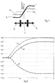
- FIG. 3 shows the signal r_ack_filter, which consists of one of one Driver caused steering wheel deltaL.
- the signal r_ack_filter provides in particular the Ackermann yaw rate filtered in the delay filter 232, which appears in the time range between 0 and 1 second as a large peak (e.g. in Form of a positive sine half-wave).
- r_ack_filter and r_by_filter react essentially equally quickly to a steering angle input. They differ only when tire saturation occurs. Without tire saturation, they are approximately the same, so about then rsoll_res ⁇ r_by_filter ⁇ r_ack_filter applies.
- a resulting yaw rate value rsoll_res results, which is also shown in FIG. 3 and serves in the subtractor 218 as an input signal for the positive input and for the formation of the variable delta_r. With this variable, multiplied by the gain factor k in the multiplier 220, the control command is generated, which in the present case represents the superposition angle deltaÜL and is fed to the summer 212.
- FIGS. 7a to 71 which the effects of a steering maneuver on a road surface with a coefficient of friction of 0.3 with a control according to the invention. They put with Circles marked graphs the steering and vehicle behavior with the invention 6 shown. The marked with crosses Graphs show the steering and vehicle behavior without such a regulation.
- FIG. 7j shows a steering deflection deltaL that initiates the control.
- the difference in subtractor 218 becomes - together with the multiplication factor k - an overlapping angle deltavÜL reached, as shown in Fig. 7l.
- the totalizer 212 gives a total steering angle, as indicated in Fig. 7k (deltavsum). This steering angle is on the wheels passed on.
- the wheel side forces are at the front (FIG. 7g) and at the rear (FIG. 7h) with a steering deflection as shown in FIG. 7j. From Fig. 7g and 7h can be seen that in the range from 0 to 2 seconds an increased Wheel side force occurs in both the front and rear areas, however in a control strategy according to the present invention after about 2 seconds returns to zero. Without control, the wheel side force would both on the front as well as the rear wheels on the increased value in the Tire force saturation remain.
- 7d shows the float angle ⁇ . 7d also shows that the vehicle can be stabilized again within 2 seconds. Without that Control strategy would skid the vehicle.
- FIG. 7c The yaw rate occurring during the driving process is shown in FIG. 7c.
- Fig. 7b the driving behavior of the vehicle, viewed from above, is shown in an XY plane. This figure shows that the driver is driving straight ahead, then make a short but powerful turn to the left and then directs straight ahead again.
- the regulation according to the invention thereby becomes more stable Way through a curve and after the steering lock the vehicle straight ahead again. Without the control strategy, however, the vehicle would deviate from the desired course and thus the street.
- FIG. 8 shows a variant for a steer-by-wire system in which the missing mechanical steering column thanks to an additional steering comfort function in the algorithm is replaced.
- the reference numerals in FIG. 8 which correspond to those from FIG. 6 designate the same control devices and elements. 8 are new only the reference symbols 802 and 804.
- the reference symbol 802 denotes the actuator not shown in the previous figures.
- the reference number 802 denotes a steering comfort function f (deltaL, ...) which is used to implement the steer-by-wire Steering is necessary.
- the actuator not shown in FIGS. 4, 5 and 6 additionally receives an actuating command from the steering comfort function 802.
- the partial actuating commands from the yaw rate control and the steering comfort function can then, as in FIG. 8 shown, summed up in summer 212 'to form the overall control command for actuator 804 become.
- control difference may be more extensive, for example additional ones Characteristic curve elements, such as dead zones or dynamic filters, can be included.
- the target yaw rate r_ack (elements 132 or 232) can also be determined by other functions such as Maps or algebraic functions then the dependence on the steering angle, the vehicle speed or other sizes.
- the presented control strategy can also be part of a more extensive control strategy for vehicle stabilization, on the one hand, the float angle or the rear slip angle etc. is limited to permissible values and / or on the other hand, additional brake interventions are added in special situations.
- FIGS. 9 and 10 Such systems are only to be indicated in FIGS. 9 and 10.
- Fig. 10 is a control strategy for a superimposed steering shown in special Situations involving brake interventions.
- the yaw rate control is in a block 1010 summarized and the actuator considered.
- control commands of the control strategy described above can only be changed from time to time in a control element 1020 (signal delta_ÜL_mod) - either during the application of brake interventions or during an activated limitation of the slip angle or the slip angle.
- FIG. 9 shows a control strategy as shown in FIG. 10, but now for one Steer-by-wire steering, with braking interventions also in special situations be added.
- the yaw rate control is again in a block 910 summarized and the actuator considered.
- Control element 920 corresponds to the control element 1020 from FIG. 10, and the elements 902 and 904 to the Elements 802 and 804 of FIG. 8.
- the present control strategy is a simple and effective one Possibility to improve driving stability in a vehicle, where you can use the known sizes in the vehicle. An otherwise required target yaw rate does not have to be determined with the present strategy become.
- the sizes used here provide information about the Tire saturation range.
Landscapes
- Engineering & Computer Science (AREA)
- Transportation (AREA)
- Mechanical Engineering (AREA)
- Chemical & Material Sciences (AREA)
- Combustion & Propulsion (AREA)
- Physics & Mathematics (AREA)
- Mathematical Physics (AREA)
- Theoretical Computer Science (AREA)
- Steering Control In Accordance With Driving Conditions (AREA)
- Control Of Driving Devices And Active Controlling Of Vehicle (AREA)
Applications Claiming Priority (2)
| Application Number | Priority Date | Filing Date | Title |
|---|---|---|---|
| DE2000109921 DE10009921A1 (de) | 2000-03-01 | 2000-03-01 | Verfahren zur Erhöhung der Fahrstabilität bei einem Fahrzeug |
| DE10009921 | 2000-03-01 |
Publications (3)
| Publication Number | Publication Date |
|---|---|
| EP1129916A2 true EP1129916A2 (fr) | 2001-09-05 |
| EP1129916A3 EP1129916A3 (fr) | 2003-07-23 |
| EP1129916B1 EP1129916B1 (fr) | 2005-10-19 |
Family
ID=7633077
Family Applications (1)
| Application Number | Title | Priority Date | Filing Date |
|---|---|---|---|
| EP20010102665 Expired - Lifetime EP1129916B1 (fr) | 2000-03-01 | 2001-02-07 | Procédé permettant d'augmenter la stabilité de conduite d'un véhicule automobile |
Country Status (3)
| Country | Link |
|---|---|
| EP (1) | EP1129916B1 (fr) |
| DE (2) | DE10009921A1 (fr) |
| ES (1) | ES2249332T3 (fr) |
Cited By (2)
| Publication number | Priority date | Publication date | Assignee | Title |
|---|---|---|---|---|
| EP1657139A2 (fr) | 2004-11-16 | 2006-05-17 | Bayerische Motoren Werke Aktiengesellschaft | Système de réglage de la dynamique de marche pour un véhicule à deux-essieus et à deux voies |
| WO2005039955A3 (fr) * | 2003-10-24 | 2007-10-11 | Bosch Gmbh Robert | Adaptation du systeme de regulation electronique du comportement dynamique a l'etat de charge d'un vehicule |
Families Citing this family (10)
| Publication number | Priority date | Publication date | Assignee | Title |
|---|---|---|---|---|
| DE10221717A1 (de) | 2002-05-16 | 2003-12-11 | Bayerische Motoren Werke Ag | Verfahren zur Erhöhung der Fahrstabilität bei einem Fahrzeug |
| JP3868848B2 (ja) * | 2002-05-23 | 2007-01-17 | 三菱電機株式会社 | 車両状態検出装置 |
| JP2004050978A (ja) * | 2002-07-19 | 2004-02-19 | Honda Motor Co Ltd | タイヤの線形領域判定装置及びタイヤの線形領域判定プログラム、並びに車両の運転操作装置及びステアバイワイヤ車両の転舵制御方法 |
| DE10355701A1 (de) * | 2003-11-28 | 2005-06-16 | Zf Friedrichshafen Ag | Verfahren zum Steuern und Regeln der Fahrdynamik eines Fahrzeugs |
| DE102004036565B4 (de) * | 2004-07-28 | 2008-12-18 | Robert Bosch Gmbh | Vorrichtung und Verfahren zum Stabilisieren eines Fahrzeugs |
| EP1902916B1 (fr) * | 2006-09-21 | 2009-07-01 | Ford Global Technologies, LLC | Direction assistée active avec rapport de direction variable pour la conduite dans des conditions limites |
| DE102006048835A1 (de) * | 2006-10-16 | 2008-04-17 | Magna Steyr Fahrzeugtechnik Ag & Co. Kg | Verfahren zur Regelung der Gierrate eines Kraftfahrzeugs |
| FR2915162B1 (fr) * | 2007-04-17 | 2009-11-13 | Peugeot Citroen Automobiles Sa | Procede de controle de stabilite en boucle fermee pour vehicule automobile. |
| DE102007000995A1 (de) * | 2007-11-28 | 2009-06-04 | Zf Lenksysteme Gmbh | Verfahren zum Betrieb einer Überlagerungslenkung für ein Kraftfahrzeug |
| EP2757007B1 (fr) * | 2013-01-17 | 2018-03-07 | Autoliv Development AB | Système de sécurité de véhicule |
Family Cites Families (2)
| Publication number | Priority date | Publication date | Assignee | Title |
|---|---|---|---|---|
| JPH10129439A (ja) * | 1996-10-25 | 1998-05-19 | Aisin Seiki Co Ltd | 車両の運動制御装置 |
| DE19749005A1 (de) * | 1997-06-30 | 1999-01-07 | Bosch Gmbh Robert | Verfahren und Vorrichtung zur Regelung von die Fahrzeugbewegung repräsentierenden Bewegungsgrößen |
-
2000
- 2000-03-01 DE DE2000109921 patent/DE10009921A1/de not_active Withdrawn
-
2001
- 2001-02-07 DE DE50107723T patent/DE50107723D1/de not_active Expired - Lifetime
- 2001-02-07 ES ES01102665T patent/ES2249332T3/es not_active Expired - Lifetime
- 2001-02-07 EP EP20010102665 patent/EP1129916B1/fr not_active Expired - Lifetime
Cited By (3)
| Publication number | Priority date | Publication date | Assignee | Title |
|---|---|---|---|---|
| WO2005039955A3 (fr) * | 2003-10-24 | 2007-10-11 | Bosch Gmbh Robert | Adaptation du systeme de regulation electronique du comportement dynamique a l'etat de charge d'un vehicule |
| EP1657139A2 (fr) | 2004-11-16 | 2006-05-17 | Bayerische Motoren Werke Aktiengesellschaft | Système de réglage de la dynamique de marche pour un véhicule à deux-essieus et à deux voies |
| DE102004055178A1 (de) * | 2004-11-16 | 2006-05-18 | Bayerische Motoren Werke Ag | Fahrdynamik Regelsystem für ein zweispuriges zweiachsiges Kraftfahrzeug |
Also Published As
| Publication number | Publication date |
|---|---|
| DE10009921A1 (de) | 2001-07-19 |
| EP1129916B1 (fr) | 2005-10-19 |
| EP1129916A3 (fr) | 2003-07-23 |
| ES2249332T3 (es) | 2006-04-01 |
| DE50107723D1 (de) | 2005-11-24 |
Similar Documents
| Publication | Publication Date | Title |
|---|---|---|
| DE4404098C2 (de) | Fahrzeugregeleinrichtung | |
| EP0487967B1 (fr) | Véhicule équipé d'une commande anti-blocage des roues | |
| EP1000838B9 (fr) | Méthode pour le contrôle des dynamiques transversales d'un véhicule avec direction pour les roues avant | |
| EP1562810B1 (fr) | Procede et dispositif de stabilisation d'un semi-remorque | |
| EP1268259B1 (fr) | Systeme de direction assistee pour vehicule a moteur | |
| DE10141425B4 (de) | Verfahren zur fahrzustandsabhängigen Lenkunterstützung | |
| EP1351843B1 (fr) | Dispositif et procede de fonctionnement d'un vehicule | |
| EP2437958B1 (fr) | Procede et systeme pour reguler la traction d'un vehicule | |
| EP1807300A1 (fr) | Procede et dispositif permettant d'assister un serveur de vehicule lors de la stabilisation d'un vehicule | |
| DE3545715A1 (de) | Einrichtung zur vortriebsregelung an kraftfahrzeugen | |
| EP2013069A1 (fr) | Procédé et dispositif de détermination d'un angle de braquage optimal lors de situations de sous-virage d'un véhicule | |
| DE102004035004A1 (de) | Verfahren zur Erhöhung der Fahrstabilität eines Kraftfahrzeugs | |
| EP2288532B1 (fr) | Dispositif et procédé destinés à agir sur la dynamique transversale d'un véhicule | |
| WO2009056412A2 (fr) | Procédé permettant de répartir un couple d'entraînement ou un couple de freinage sur les roues motrices d'un véhicule motorisé | |
| EP0897359A1 (fr) | Procede pour determiner le comportement theorique d'un vehicule | |
| EP1129916A2 (fr) | Procédé permettant d'augmenter la stabilité de conduite d'un véhicule automobile | |
| WO2008046586A2 (fr) | Procédé de régulation de la vitesse de lacet d'un véhicule à moteur | |
| EP1890920A1 (fr) | Regulation de dynamique de vehicule adaptee a l'etat de mouvement et fondee sur des interventions sur l'angle de braquage | |
| DE102005037479B4 (de) | Fahrdynamik-Steuerungssystem für ein zweispuriges Kraftfahrzeug | |
| DE102008034908A1 (de) | Verfahren zur Stabilisierung eines Fahrzeuges bei Aquaplaning | |
| DE19549715B4 (de) | Verfahren zur Bestimmung des Fahrbahnreibwertes für ein Steuersystem in einem Kraftfahrzeug | |
| DE102005012548A1 (de) | Verfahren und Lenkvorrichtung zum Erhöhen der Fahrstabilität eines Fahrzeugs während der Fahrt durch eine Kurve | |
| DE102005012584B4 (de) | Verfahren und Vorrichtung zum Erhöhen der Fahrstabilität eines Fahrzeugs während der Fahrt durch eine Kurve | |
| EP1799484B1 (fr) | Procede et dispositif pour regler le degre de verrouillage d'un systeme de verrouillage de differentiel a commande electronique | |
| DE10141273A1 (de) | Verfahren zur Erhöhung der Fahrstabilität bei einem Fahrzeug |
Legal Events
| Date | Code | Title | Description |
|---|---|---|---|
| PUAI | Public reference made under article 153(3) epc to a published international application that has entered the european phase |
Free format text: ORIGINAL CODE: 0009012 |
|
| AK | Designated contracting states |
Kind code of ref document: A2 Designated state(s): AT BE CH CY DE DK ES FI FR GB GR IE IT LI LU MC NL PT SE TR |
|
| AX | Request for extension of the european patent |
Free format text: AL;LT;LV;MK;RO;SI |
|
| PUAL | Search report despatched |
Free format text: ORIGINAL CODE: 0009013 |
|
| AK | Designated contracting states |
Designated state(s): AT BE CH CY DE DK ES FI FR GB GR IE IT LI LU MC NL PT SE TR |
|
| AX | Request for extension of the european patent |
Extension state: AL LT LV MK RO SI |
|
| 17P | Request for examination filed |
Effective date: 20030807 |
|
| AKX | Designation fees paid |
Designated state(s): DE ES FR GB IT SE |
|
| 17Q | First examination report despatched |
Effective date: 20040804 |
|
| GRAP | Despatch of communication of intention to grant a patent |
Free format text: ORIGINAL CODE: EPIDOSNIGR1 |
|
| GRAS | Grant fee paid |
Free format text: ORIGINAL CODE: EPIDOSNIGR3 |
|
| GRAA | (expected) grant |
Free format text: ORIGINAL CODE: 0009210 |
|
| AK | Designated contracting states |
Kind code of ref document: B1 Designated state(s): DE ES FR GB IT SE |
|
| REG | Reference to a national code |
Ref country code: GB Ref legal event code: FG4D Free format text: NOT ENGLISH |
|
| REF | Corresponds to: |
Ref document number: 50107723 Country of ref document: DE Date of ref document: 20051124 Kind code of ref document: P |
|
| GBT | Gb: translation of ep patent filed (gb section 77(6)(a)/1977) |
Effective date: 20051130 |
|
| REG | Reference to a national code |
Ref country code: SE Ref legal event code: TRGR |
|
| REG | Reference to a national code |
Ref country code: ES Ref legal event code: FG2A Ref document number: 2249332 Country of ref document: ES Kind code of ref document: T3 |
|
| ET | Fr: translation filed | ||
| PLBE | No opposition filed within time limit |
Free format text: ORIGINAL CODE: 0009261 |
|
| STAA | Information on the status of an ep patent application or granted ep patent |
Free format text: STATUS: NO OPPOSITION FILED WITHIN TIME LIMIT |
|
| 26N | No opposition filed |
Effective date: 20060720 |
|
| REG | Reference to a national code |
Ref country code: FR Ref legal event code: PLFP Year of fee payment: 16 |
|
| REG | Reference to a national code |
Ref country code: FR Ref legal event code: PLFP Year of fee payment: 17 |
|
| REG | Reference to a national code |
Ref country code: FR Ref legal event code: PLFP Year of fee payment: 18 |
|
| PGFP | Annual fee paid to national office [announced via postgrant information from national office to epo] |
Ref country code: IT Payment date: 20200221 Year of fee payment: 20 Ref country code: SE Payment date: 20200224 Year of fee payment: 20 Ref country code: DE Payment date: 20200221 Year of fee payment: 20 Ref country code: ES Payment date: 20200320 Year of fee payment: 20 Ref country code: GB Payment date: 20200225 Year of fee payment: 20 |
|
| PGFP | Annual fee paid to national office [announced via postgrant information from national office to epo] |
Ref country code: FR Payment date: 20200220 Year of fee payment: 20 |
|
| REG | Reference to a national code |
Ref country code: DE Ref legal event code: R071 Ref document number: 50107723 Country of ref document: DE |
|
| REG | Reference to a national code |
Ref country code: GB Ref legal event code: PE20 Expiry date: 20210206 |
|
| REG | Reference to a national code |
Ref country code: SE Ref legal event code: EUG |
|
| PG25 | Lapsed in a contracting state [announced via postgrant information from national office to epo] |
Ref country code: GB Free format text: LAPSE BECAUSE OF EXPIRATION OF PROTECTION Effective date: 20210206 |
|
| REG | Reference to a national code |
Ref country code: ES Ref legal event code: FD2A Effective date: 20210604 |
|
| PG25 | Lapsed in a contracting state [announced via postgrant information from national office to epo] |
Ref country code: ES Free format text: LAPSE BECAUSE OF EXPIRATION OF PROTECTION Effective date: 20210208 |
|
| P01 | Opt-out of the competence of the unified patent court (upc) registered |
Effective date: 20230419 |