EP1129929B1 - Structure de plancher pour automobile - Google Patents
Structure de plancher pour automobile Download PDFInfo
- Publication number
- EP1129929B1 EP1129929B1 EP01301897A EP01301897A EP1129929B1 EP 1129929 B1 EP1129929 B1 EP 1129929B1 EP 01301897 A EP01301897 A EP 01301897A EP 01301897 A EP01301897 A EP 01301897A EP 1129929 B1 EP1129929 B1 EP 1129929B1
- Authority
- EP
- European Patent Office
- Prior art keywords
- floor
- rigidity region
- vehicle
- cross
- wall
- Prior art date
- Legal status (The legal status is an assumption and is not a legal conclusion. Google has not performed a legal analysis and makes no representation as to the accuracy of the status listed.)
- Expired - Lifetime
Links
- 230000003313 weakening effect Effects 0.000 claims description 12
- 239000000725 suspension Substances 0.000 claims description 10
- 239000011324 bead Substances 0.000 claims description 7
- 238000001125 extrusion Methods 0.000 claims description 4
- 239000000463 material Substances 0.000 claims description 3
- 230000002787 reinforcement Effects 0.000 claims description 2
- 230000015572 biosynthetic process Effects 0.000 claims 1
- 229910052751 metal Inorganic materials 0.000 description 7
- 239000002184 metal Substances 0.000 description 7
- 229910000838 Al alloy Inorganic materials 0.000 description 4
- 235000019589 hardness Nutrition 0.000 description 3
- 230000005540 biological transmission Effects 0.000 description 2
- 230000003247 decreasing effect Effects 0.000 description 2
- 241001312218 Arisaema triphyllum Species 0.000 description 1
- 235000006481 Colocasia esculenta Nutrition 0.000 description 1
- 238000010521 absorption reaction Methods 0.000 description 1
- 239000000853 adhesive Substances 0.000 description 1
- 230000001070 adhesive effect Effects 0.000 description 1
- 239000006185 dispersion Substances 0.000 description 1
- 238000009826 distribution Methods 0.000 description 1
- 230000005284 excitation Effects 0.000 description 1
- 239000002828 fuel tank Substances 0.000 description 1
- 238000005304 joining Methods 0.000 description 1
- 238000003754 machining Methods 0.000 description 1
- 238000000034 method Methods 0.000 description 1
- 238000012986 modification Methods 0.000 description 1
- 230000004048 modification Effects 0.000 description 1
- 238000000465 moulding Methods 0.000 description 1
- 230000002093 peripheral effect Effects 0.000 description 1
- 238000003825 pressing Methods 0.000 description 1
- 238000005728 strengthening Methods 0.000 description 1
Images


Classifications
-
- B—PERFORMING OPERATIONS; TRANSPORTING
- B62—LAND VEHICLES FOR TRAVELLING OTHERWISE THAN ON RAILS
- B62D—MOTOR VEHICLES; TRAILERS
- B62D25/00—Superstructure or monocoque structure sub-units; Parts or details thereof not otherwise provided for
- B62D25/20—Floors or bottom sub-units
- B62D25/2009—Floors or bottom sub-units in connection with other superstructure subunits
- B62D25/2036—Floors or bottom sub-units in connection with other superstructure subunits the subunits being side panels, sills or pillars
-
- B—PERFORMING OPERATIONS; TRANSPORTING
- B62—LAND VEHICLES FOR TRAVELLING OTHERWISE THAN ON RAILS
- B62D—MOTOR VEHICLES; TRAILERS
- B62D21/00—Understructures, i.e. chassis frame on which a vehicle body may be mounted
- B62D21/15—Understructures, i.e. chassis frame on which a vehicle body may be mounted having impact absorbing means, e.g. a frame designed to permanently or temporarily change shape or dimension upon impact with another body
- B62D21/157—Understructures, i.e. chassis frame on which a vehicle body may be mounted having impact absorbing means, e.g. a frame designed to permanently or temporarily change shape or dimension upon impact with another body for side impacts
-
- B—PERFORMING OPERATIONS; TRANSPORTING
- B62—LAND VEHICLES FOR TRAVELLING OTHERWISE THAN ON RAILS
- B62D—MOTOR VEHICLES; TRAILERS
- B62D25/00—Superstructure or monocoque structure sub-units; Parts or details thereof not otherwise provided for
- B62D25/20—Floors or bottom sub-units
- B62D25/2009—Floors or bottom sub-units in connection with other superstructure subunits
- B62D25/2027—Floors or bottom sub-units in connection with other superstructure subunits the subunits being rear structures
-
- B—PERFORMING OPERATIONS; TRANSPORTING
- B62—LAND VEHICLES FOR TRAVELLING OTHERWISE THAN ON RAILS
- B62D—MOTOR VEHICLES; TRAILERS
- B62D25/00—Superstructure or monocoque structure sub-units; Parts or details thereof not otherwise provided for
- B62D25/02—Side panels
- B62D25/025—Side sills thereof
Definitions
- the present invention relates generally to a floor structure for automotive vehicles, and more particularly to a joint structure for joining side sills extending longitudinally of a vehicle body on both sides of a front floor, a rear seat cross member installed on a rear floor connected to the rear of the front floor, and rear side-members extending longitudinally of the vehicle body on both sides of the rear floor.
- Japanese Patent First Publication No. 7-165124 teaches a joint structure for floor frame members of an automotive vehicle.
- a front end portion of each rear side-member is connected along an inner side surface of a rear end portion of a corresponding side sill.
- Each end of a rear seat cross-member extending in a widthwise direction of a vehicle body passes through one of the rear side-members perpendicular thereto and connects with the inner side surface of one of the side sills, thereby strengthening a connection of three types of these floor frame members to increase the rigidity of a rear portion of a vehicle cabin for reducing undesirable mechanical vibrations.
- Using the extruded front floor increases impact energy absorption and maintains cabin space for a passenger by decreasing lateral deformation of the front floor, since the front floor is extruded in a longitudinal direction and the impact from a center pillar studded on a side sill is perpendicular, so the buckling deformation from the impact is distributed over the floor owing to the longitudinal stiffness of the floor.
- the suggested three-member high strength structure (the side sill, the rear sheet cross-member, and the rearside member) has a possibility to prevent deformation of the side sill or the front floor rear part and may prevent an ideal buckling deformation mode of the floor.
- EP-A-0937631 discloses a vehicle floor in accordance with the preambles of claims 1 and 10.
- US-A-5984402 describes a sidebody structure of a vehicle in which side impact energy is absorbed by deformation of a side sill and buckling of a floor panel.
- the side sill bends at a strength discontinuity portion in the connecting portion between a center pillar and the side sill.
- the present invention provides a vehicle floor as set forth in claim 1.
- the invention provides a vehicle floor as set forth in claim 10.
- Fig. 1 there is shown a floor structure of an automotive vehicle body.
- the floor of the vehicle as described below, has a mirror-image structure about the longitudinal center-line, and the following discussion will refer basically only to the left side of the floor for the sake of simplicity of disclosure.
- the vehicle floor includes a front floor 1 and a rear floor 3.
- the front floor 1 connects at a front end thereof to a dash cross-member 2.
- the rear floor 3 connects with a rear end of the front floor 1.
- Rear side-members 5 (only one of which is shown for simplicity of illustration) are installed on ends of the rear floor 3 and extend in the longitudinal direction of the vehicle body.
- a rear seat cross member 4 is disposed on a connection of the rear floor 3 with the front floor 1 extending in a widthwise direction of the vehicle.
- Side sills 6 are disposed on right and left sides of the front floor 1 and extend in a longitudinal direction of the vehicle over the rear end of the front floor 1.
- the rear seat cross-member 4 as clearly shown in Fig. 2, has a substantially L-shaped cross-section and connects through a flange 4a formed on an upper edge thereof with a portion of the rear floor 3 on a rear side of a front end which is bent downward, thereby forming a closed hollow frame member extending in the widthwise direction of the vehicle.
- Each of the rear side-members 5 is cylindrical and serves as one of longitudinal frame members.
- Each of the side sills 6 is made of a closed hollow member and serves as one of the longitudinal frame members.
- right and left front side members 7 are joined to front side portions of the dash cross-member 2.
- the front side members 7 extend longitudinally of the vehicle and connect at front ends thereof with a first cross-member 8 and a bumper armature 9.
- the front side members 7, the first cross member 8, and the bumper armature 9 form a framework of a front compartment F.C.
- the vehicle body also includes front pillars 11, center pillars 12, rear pillars 13, rear fenders 14, a roof panel 15, and strut housings 16 serving as main frame members of the front compartment F.C.
- the front floor 1 (as shown in Figs. 1 to 5) includes flat pans 1A, a center tunnel 1B extending longitudinally of the vehicle between the flat pans 1A, and side sill portions 1C.
- the front floor 1 in this embodiment is formed by extruding a lightweight metal such as aluminum alloy to have a hollow structure, as shown in Figs. 2 and 5, in which a plurality of ribs 23 extending longitudinally of the vehicle are disposed between inner and outer walls 21 and 22.
- Each of the center pillars 12 is (as clearly shown in Fig. 1) disposed closer to the front of the vehicle than the rear seat cross-member 4 and connects at a lower base 12A thereof integrally with one of sill outers 12B extending in the longitudinal direction of the vehicle.
- the sill outers 12B are welded to outer side surfaces of the side sill portions 1C to form the side sills 6, respectively.
- the side sills 6 each have a double closed hollow structure in the widthwise direction of the vehicle together with the side sill portion 1C and the side outer 12B.
- Cut-away portions 1D are formed in front portions of the flat pans 1A of the front floor 1 which range from the tunnel 1B to the side sill portions 1C.
- the dash cross-member 2 is formed by extruding the same lightweight metal as that of the front floor 1 in the widthwise direction of the vehicle to have a closed hollow structure.
- the dash cross-member 2 has a toe board 2A formed integrally.
- the toe board 2A has flat joint portions 2B extending backward from a lower edge of an inclined portion thereof.
- the flat joint portions 2B have a closed hollow structure and are welded in the cut-away portions 1D to form flat floor surfaces flush with the flat floor pans 1A.
- Each of the side sill portions 1C is (as clearly shown in Fig. 4) welded at a front edge thereof to one of the sides of the toe board 2A of the dash cross-member 2.
- the reference number 25 denotes joint members (only a left one is shown for simplicity of illustration) each of which joins a rear extension 6a of one of the side sills 6, one end of the rear seat cross-member 4, and the front end of one of the rear side-members 5.
- the joint member 25 has a closed hollow structure and is made up of a lower member 25L and an upper member 25U which are made of the same lightweight metal as that of the front floor 1.
- the lower member 25L is made up of a member body 25L 1 , an arm 25L 2 , and an arm base 25L 3 .
- the member body 25L 1 is disposed between the end of the rear seat cross member 4 and the rear extension 6a of the side sill 6, or an extension 1C ⁇ E of the side sill portion 1C.
- the arm 25L 2 is disposed inside the member body 25L 1 and connects with the front end of the rear side-member 5 substantially in alignment with the front portion of the rear side member 5.
- the arm base 25L 3 extends in the widthwise direction of the vehicle from the front end of the arm 25L 2 to connect the arm 25L 2 to the member body 25L 1 .
- the member body 25L 1 consists of a bottom wall 26, an inner side wall 27, a rear wall 28, and a corner wall 29.
- the corner wall 29 is oriented substantially perpendicular to the arm base 25L3 and connects the side wall 27 and the rear wall 28.
- the arm 25L 2 and the arm base 25L 3 are connected together and formed by a bottom wall 31, an inner side wall 32, and an outer side wall 33.
- the bottom wall 31 extends from an upper edge of the comer wall 29 of the member body 25L 1 .
- the inner side wall 32 extends from the side wall 27 of the member body 25L 1 .
- the outer side wall 33 extends from the rear wall 28 of the member body 25L 1 .
- a portion of the bottom wall 31 of the arm base 25L3 connecting with the upper edge of the corner wall 29 forms a flat shelf 34.
- the bottom wall 26 of the member body 25L 1 connects with a lower surface of the rear end of the flat pan 1A of the front floor 1 and a lower surface of the extension 1C ⁇ E of the side sill portion 1C.
- the rear wall 28 connects directly with the rear end of the extension 1C ⁇ E of the side sill portion 1C.
- a flange 30 is formed over the upper edge of the inner side wall 27 of the member body 25L 1 and the upper edge of the inner side wall 32 of the arm 25L 2 to connect the side walls 27 and 32 to a side edge of the rear floor 3.
- the rear seat cross-member 4 is connected at each end thereof to the inner side wall 27 through the flange 4a. With this arrangement, the lower member 25L is connected to the extension 1C ⁇ E of the side sill portion 1C, the rear seat cross member 4, and the rear side-member 5.
- the upper member 25U is formed by a front wall 35, an outer side wall 36 and an upper wall 37 and installed on the lower member 25L.
- the upper wall 37 covers an area ranging from the member body 25L 1 of the lower member 25L to the arm 25L 2 and has a constant width extending longitudinally from an inside side edge.
- the front wall 35 has an upper half which is angled backward to be contoured to the front end of the rear floor 3 and connected to an end of the upper wall 37.
- the side wall 36 is inclined slightly inward of the vehicle body from the upper edge of the rear extension 1C ⁇ E of the side sill portion 1C to the side edge of the upper wall 37.
- the upper member 25U is fitted on the lower member 25L coupled to the three floor frame members 4, 5, and 6.
- the upper member 25U has a flange 25a formed on a lower edge of the front wall 35 joined to the rear end upper surface of the floor pan 1A and a flange 36a formed on a lower edge of the side wall 36 secured to the upper edge of the rear extension 1C ⁇ E of the side sill portion 1C to connect an inside side edge and a rear edge of the upper wall 37 to a side edge of the rear floor 3 and a rear end of the arm 25L 2 of the lower member 25L, respectively.
- the upper member 25U also has a flange 37a formed over an outside side edge of the upper wall 37 and the rear end of the side wall 36.
- the flange 37a is joined to the side wall 33 extending from the arm 25L 2 of the lower member 25L to the arm base 25L 3 and the rear wall 28 of the member body 25L 1 to define a closed hollow structure.
- a lower-rigidity region A W is defined in the inside of the joint member 25 which faces the end of the rear seat cross-member 4.
- an upstanding rib 41 is installed backward from a connection of the joint member 25 to the end of the rear seat cross-member 4 to define a higher-rigidity region A H offset backward from the end of the rear seat cross-member 4, thereby defining the lower-rigidity region A W in the joint member 25 adjacent the end of the rear seat cross-member 4.
- the rib 41 has a height close to or in contact with the upper member 25U to define a plurality of closed chambers in the higher-rigidity region A H .
- the rib 41 is made up of a first rib 41a, a second rib 41b, a third rib 41c, and a fourth rib 41d which are connected integrally at ends thereof.
- the first rib 41a is disposed on the bottom wall 26 of the member body 25L 1 and connected at one end thereof to a portion of the side wall 27 joined to a rear edge of the end of the rear seat cross member 4 and at the other end to a rear side surface of the rear extension 1C ⁇ E of the side sill portion 1C.
- the first rib 41a has a plane surface oriented backward from the end of the rear seat cross-member 4 toward the rear end of the rear extension 1C ⁇ E and a flange 42 formed on the outer end thereof.
- the flange 42 is coupled to the inner side wall of the rear extension 1C ⁇ E.
- the second rib 41 b is, like the first rib 41a, disposed on the bottom wall 26 of the member body 25L 1 and extends from the inner side wall of the rear extension 1C ⁇ E to a joint of the corner wall 29 and the inner side wall 27.
- the third rib 41c is disposed on the bottom wall 31 and the shelf 34 of the arm base 25L 3 and extends longitudinally of the vehicle body from the inside end of the second rib 41b to a joint of the arm base 25L 3 and the arm 25L 2 of the side wall 33.
- the fourth rib 41d is disposed on the shelf 34 and extends from a joint of the side wall 33 of the arum base 25L 3 and the rear wall 28 of the member body 25L 1 to the side wall 32 of the arm base 25L 3 so that an intersection of itself and the third rib 41c may lie substantially at the center of the shelf 34.
- a boss 43 is formed integrally on the shelf 34 adjacent the intersection of the third and fourth ribs 41c and 41d.
- a stud bolt 44 is installed in a lower end of the boss 43 which projects from the bottom of the shelf 34 to serve as a sub-frame mounting member on which a sub-frame 45 is mounted using a nut 46.
- three floor frame members the rear extension 6a of the side sill 6, the end of the rear seat cross-member 4, and the front end of the rear side-member 5 are fixed by the joint member 25 so as to have the closed hollow structure ensuring the rigidity usually required by the floor of the vehicle body.
- the front floor 1 is, as described above, so formed in the extrusion as to have the closed hollow structure and so arranged that the extrusion direction is in parallel to the longitudinal direction of the vehicle body. This allows the buckling of the vehicle body in the width-wise direction thereof caused by the impact transmitted from the center pillar 12 to the side sill 6 when the vehicle is involved in a side collision to spread easily from the pillar base 12A and the side sill 6 in the longitudinal direction of the vehicle body.
- an impact F acts on the center pillar 12 upon occurrence of the side collision of the vehicle body, and a component F1 of the impact F is transmitted to the front floor 1 through the pillar base 12A
- the lower-rigidity region A W provided in the joint member 25 adjacent the end of the rear seat cross-member 4 facilitates (as shown in Fig. 3) the buckling of the side sill 6 etc. inside the vehicle cabin. This achieves an ideal deformation mode in which the side sill 6 (as shown in Fig.
- the lower-rigidity region A W facing the end of the rear seat cross-member 4 is, as described above, provided by defining the higher-rigidity region A H in the inside of the joint member 25 offset from the end of the rear seat cross-member 4 in the longitudinal direction of the vehicle body.
- the rigidity of the joint of the side sill 6 and the rear side-member 5 is, thus, increased by the higher-rigidity region A H , thereby providing a higher resistance to the rear end of the extension 6a of the side sill 6 against the impact F acting on the pillar base 12A upon occurrence of the side collision, facilitating lateral collapse of the vehicle body in the lower-rigidity region A W .
- the first rib 41a disposed at the front of the rib 41 extends, as described above, at a given angle to the longitudinal center-line of the vehicle body from the end of the rear seat cross-member 4 to the rear end of the rear extension 1C ⁇ E of the side sill portion 1C, thereby increasing an outside area of the lower-rigidity region A W to facilitate the ease of the lateral collapse of the vehicle body into the lower-rigidity region A W .
- the higher-rigidity region A H is formed by the rib 41 made up of the first, second, third, and fourth ribs 41a to 41d to have the closed hollow structure, so that the load is dispersed over the rib 41 and the peripheral wall of the joint member 25, thereby providing a high degree of rigidity to the connection of the rear extension 6a of the side sill 6, the end of the rear seat cross-member 4, and the front end of the rear side-member 5 against vertical and lateral impacts produced by a vehicle collision.
- the first and second ribs 41a and 41b couple the connection of the joint member 25 and the rear seat cross-member 4 and the connection of the joint member 25 and the side sill 6, thereby avoiding deformation of either or both of the connections, resulting in an increase in rigidity against lateral and torsional impacts.
- the third rib 41c intersects the fourth rib 41d, thereby increasing the rigidity in the higher-rigidity region A H , especially on the shelf 34.
- the stud bolt 44 for mounting the sub-frame 45 is installed near the intersection of the third and fourth ribs 41c and 41d, so that vertical, lateral, or longitudinal impact transmitted from the sub-frame 45 is received by the shelf 34, thus resulting in desirable transmission or dispersion of the impact over the rear side-member 5, the side sill 6, and the rear seat cross-member 4 through the whole of the higher-rigidity region A H , thereby minimizing physical excitation of the rear side-member 5 to reduce the vibration thereof.
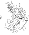
- Figs. 6 and 7 shows a second embodiment of the invention.
- the same reference numbers as employed in the first embodiment refer to the same parts, and explanation thereof in detail will be omitted here.
- a suspension mount 51 is provided in the higher-rigidity region A H of the joint member 25 which supports an end of a rear suspension 52 pivotably.
- a tie-down hook 53 is installed near the suspension mount 51.
- the bottom wall 26 of the member body 25L 1 of the lower member 25L consists of two sections: a front bottom wall 26a and a rear bottom wall 26b.
- the front bottom wall 26a is located in the lower-rigidity region A W
- the rear bottom wall 26b is located in the higher-rigidity region A H and connects at front and side edges thereof with upstanding walls 54 and 55.
- the rear bottom wall 26b is higher in level than the front bottom wall 26a.
- the upstanding wall 54 extends at substantially the same angle to the longitudinal center line of the vehicle body as that of the rib 41a.
- An upstanding wall 55 extends in parallel to the rear extension 1C ⁇ E of the side sill portion 1C at a given interval away therefrom.
- the higher-rigidity region A H is, like the first embodiment, formed by a rib 56 made up of first to seventh ribs 56a to 56g.
- the first rib 56a extends upward from an upper edge of the upstanding wall 54.
- the second rib 56b extends perpendicular to the rear extension 1C ⁇ E and connects at one end thereof with a junction of the upstanding walls 54 and 55 and an outer end of the first rib 56a on the bottom wall 26a and at the other end thereof with an inner surface of the rear extension 1C ⁇ E.
- the third rib 56c extends on the rear bottom wall 26b and connects at one end thereof with the junction of the upstanding walls 54 and 55 and at the other end with the side wall 27 of the member body 25L 1 in alignment with the second rib 56b.
- the fourth rib 56d extends on the rear bottom wall 26b in parallel to the third rib 56c and connects at one end thereof with a junction of the rear wall 28 of the member body 25L 1 and the side wall 33 of the arm base 25L 3 and at the other end thereof with the side wall 32 opposed to the side wall 33.
- the fifth rib 56e extends downward from the lower surface of the rear bottom wall 26b at a given interval away from and in parallel to the upstanding wall 55 and has the same width as that of the upstanding wall 55.
- the sixth rib 56f connects at an outer edge thereof with a front edge of the fifth rib 56e and extends from the lower edge of the third rib 56c in alignment with the third rib 56c.
- the seventh rib 56g connects at an outer edge thereof with a rear edge of the fifth rib 56e and extends from the lower edge of the fourth rib 56d in alignment with the fourth rib 56d.
- the upstanding wall 55 and the fifth rib 56e have rear suspension support holes 57 formed in alignment with the width-wise direction of the vehicle body and serve as a bracket for mounting the rear suspension 52.
- the upstanding walls 54 and 55 physically function as part of the rib 56.
- the upstanding wall 55 also serves as the bracket for mounting the rear suspension 52.
- the tie-down hook 53 is installed on a rear extension of the front bottom wall 26a surrounded by the rear extension 1C ⁇ E of the side sill portion 1C, the rear wall 28 of the member body 25L 1 , the upstanding wall 55, and the second rib 56b.
- the upper edge of the second rib 56b is inclined downward from the junction of the first and third ribs 56a and 56c to the upper edge of the rear extension 1C ⁇ E of the side sill portion 1C.
- a groove 58 is formed in an inner surface of the side wall 36 of the upper member 25U for engagement with the upper edge of the second rib 56b when the upper member 25U is fitted on the rib 56.
- An adhesive may be loaded into a junction of the upper edge of the second rib 56b and the groove 58 for reducing lower sound.
- the front bottom wall 26a of the member body 25L 1 in the lower-rigidity region A W is inclined from a lower side edge of the rear extension 1C ⁇ E of the side sill portion 1C to the joint of the side wall 27 and a lower edge of the end of the rear seat cross-member 4 and has a weakening portion 61 designed to facilitate lateral collapse of the front bottom wall 26a caused by the impact in the widthwise direction of the vehicle body upon occurrence of a side collision of the vehicle.
- the weakening portion 61 is provided by double beads 61a which are formed in a portion of the front bottom wall 26a close to the rear extension 1C ⁇ E and extend in parallel to the rear extension 1C ⁇ E, but may alternatively be provided by slits.
- the lower-rigidity region A W facing the end of the rear seat cross-member 4 is, as described above, provided by defining the higher-rigidity region A H in the inside of the joint member 25 offset from the end of the rear seat cross-member 4 in the longitudinal direction of the vehicle body so that a side area thereof may be increased outward of the vehicle.
- the rigidity of the joint of the side sill 6 and the rear side-member 5 is, like the first embodiment, increased, thereby achieving the ideal deformation mode as described in the first embodiment.
- the front bottom wall 26a of the member body 25L 1 in the lower-rigidity region A W has formed therein the beads 61a to form the weakening portion 61 to facilitate the lateral collapse of the front bottom wall 26a subjected to the lateral impact upon occurrence of a side collision of the vehicle, thereby also facilitating the ease of lateral collapse of the joint member 25 into the lower-rigidity region A W .
- the suspension mount 51 is provided in a higher-rigidity portion of the rib 56 in the higher-rigidity region on which the first to seventh ribs 56a to 56g are concentrated, so that the vertical, lateral, or longitudinal impact transmitted from the rear suspension 52 is received by the higher-rigidity portion of the rib 56 and transmitted to the rear side-member 5, the side sill 6, and the rear seat cross-member 4 through the whole of the higher-rigidity region A H , thereby minimizing physical vibrations thereof.
- the second rib 56b is joined to the upper member 25U through the groove 58, thus facilitating desirable transmission of the impact to the upper member 25U.
- the tie-down hook 53 is installed adjacent the suspension mount 51, thus resulting in an increase in rigidity of the tie-down hook 53.
- Figs. 8 shows a third embodiment of the invention in which the rib 56 is concentrated on a rear section of the higher-rigidity region A H as compared with the second embodiment.
- the rib 56 is made up of first to ninth ribs 56a to 56i.
- the eighth rib 56h is disposed on the rear bottom wall 26b of the member body 25L 1 of the lower member 25L and extends from a middle portion of the first rib 56a to a middle portion of the side wall 33 of the arm base 25L3 in vertical alignment with the firth rib 56e perpendicular to the third and fourth ribs 56c and 56d.
- the ninth rib 56i extends from a junction of the front end of the eighth rib 56h and the first rib 56a to the side wall 27 of the member body 25L 1 in parallel to the third and fourth ribs 56c and 56d. This increases the rigidity of the rear section of the higher-rigidity region A H , that is, the connection of the side sill 6 and the rear side-member 5 as compared with the second embodiment.
- an upstanding rib 56j may be installed in the lower-rigidity region A W which extends laterally of the vehicle body from a central portion of the end of the rear seat cross-member 4 to the rear extension 1C ⁇ E of the side sill portion 1C.
- Fig. 9 shows a fourth embodiment of the invention which is different from the above embodiments only in that the higher-rigidity region A H and the lower-rigidity region A W of the joint member 25 are provided by changing the thickness of the joint member 25.
- Other arrangements are identical, and explanation thereof in detail will be omitted here.
- a reinforcement plate 62 is joined on the bottom wall 26 of the member body 25L 1 of the lower member 25L to increase the thickness of the joint member 25 partially, thereby increasing the rigidity of a rear portion of the joint member 25 to define the higher-rigidity region A H .
- the weakening portion 61 in the lower-rigidity region A W is formed by machining a plurality of slits 61b in a front portion of the upper member 25U perpendicular to a front ridge of the upper member 25U, thereby facilitating the ease of a lateral collapse of the lower-rigidity region A W upon occurrence of a side collision of the vehicle.
- Fig. 10 shows a fifth embodiment of the invention in which the higher-rigidity region A H and the lower-rigidity region A H of the joint member 25 are, like the fourth embodiment, provided by changing the thickness of the joint member 25.
- the lower member 25L is made up of two parts: a front half and a rear half which are bonded or welded together.
- the rear half is formed by a portion of the lower member 25L ranging from the middle of the member body 25L 1 to the arm 25L 3 and has the thickness smaller than that of the remaining portion of the lower member 25L to define the lower-rigidity region A H .
- the higher-rigidity region A H and the lower-rigidity region A H may alternatively be formed by making the front half and the rear half of the lower member 25L of materials having different hardnesses without changing the thickness thereof.
- the front half of the lower member 25L is cast in a lightweight metal such as an aluminum alloy, while the rear half is cast in material having a higher hardness or made by pressing a metal plate having a higher hardness to define the higher-rigidity region A H .
- Fig. 11 shows a sixth embodiment of the invention in which each end of the rear seat cross-member 4 is joined to the side wall of the side sill portion 1C directly using the flange 4a.
- the rear seat cross-member 4, the rear extension 1C ⁇ E of the side sill portion 1C, and the rear side member 5 are joined through a joint member 71.
- the joint member 71 is, like the joint member 25 in the first to third embodiments, made of a lightweight metal such as an aluminum alloy.
- the joint member 71 includes a body 71A, an arm 71B, and an arm base 71C.
- the body 71A is secured to a corner portion defined by an end portion of the rear wall of the rear seat cross-member 4 and the side wall of the rear extension 1C ⁇ E of the side sill portion 1C.
- the arm 71B is offset inwardly (in a longitudinal center-line thereof) from the body 71A and extends substantially in alignment with the rear side-member 5.
- the arm 71B is connected to the front end of the rear side-member 5.
- the arm base 71C has a longitudinal center line thereof biased outwardly and connects between the arm 71B and the body 71A.
- the body 71A includes a bottom wall 72, a side wall 73, and a rear wall 74 and defines a box-like shape along with the rear wall of the rear seat cross-member 4 and the rear extension 1C ⁇ E.
- the body 71A also includes upstanding ribs 75 which extend on the bottom wall 72 from the side wall 73 and the side wall of the rear extension 1C ⁇ E in the width-wise direction of the vehicle body.
- the arm 71B and the arm base 71C have a common bottom wall 76, a common inner side wall 77, and a common outer side wall 78.
- the bottom wall 76 has a front portion inclined downward from the arm base 71C to the bottom wall 72 of the body 71A.
- the inner side wall 77 continues the side wall 73 of the body 71A.
- the outer side wall 78 continues the rear wall 74 of the body 71A.
- the bottom wall 72 of the body 71A is joined to a lower surface of the rear end of the rear seat cross-member 4 and the side wall of the rear extension 1C ⁇ E through a flange 72a.
- the rear wall 74 is joined to the rear end of the rear extension 1C ⁇ E.
- Each of the upstanding ribs 75 has a flange 75a formed on an outer end thereof and is joined to the side wall of the rear extension 1C ⁇ E through the flange 75a.
- the body 71A and the arm 71B have a common flange 79 formed on ends thereof.
- the flange 79 extends from the front end of the body 71A to the upper ends of the body 71A and the side wall 77 and connects at a front portion thereof to the rear wall of the rear seat cross-member 4 and at an upper portion thereof to the rear floor 3.
- the rear floor 3 covers the whole of a connection of the rear seat cross-member 4, the side sill portion 1C, and the joint member 71 to define closed chambers together with the joint member 71 and the rear seat cross-member 4.
- the lower-rigidity region A W is provided in an end portion of the rear seat cross-member 4 joined to the side sill portion 1C.
- the lower-rigidity region A W is defined by providing the weakening portion 61 which facilitates the ease of a lateral collapse of the vehicle body upon occurrence of a side collision of the vehicle.
- the weakening portion 61 is made by forming a plurality of beads 61a in an outside portion of the rear seat cross-member 4 perpendicular to a ridge thereof and in an outside portion of the rear floor 3 perpendicular to a front ridge thereof. Instead of the beads 61a, slits may be formed.
- the weakening portion 61 may instead be formed only in the rear seat cross-member 4.
- the rear extension 6a of the side sill 6, the rear seat cross-member 4, and the rear side-member 5 are fixed by the joint member 71 so as to have the closed hollow structure ensuring the rigidity usually required by the floor of the vehicle body.
- the lower-rigidity region A W provided in the end of the rear seat cross-member 4 serves to facilitate the inward buckling of the rear seat cross-member 4 when the vehicle is involved in a side collision, thereby establishing the ideal deformation mode, as described above.
Landscapes
- Engineering & Computer Science (AREA)
- Chemical & Material Sciences (AREA)
- Combustion & Propulsion (AREA)
- Transportation (AREA)
- Mechanical Engineering (AREA)
- Body Structure For Vehicles (AREA)
Claims (13)
- Plancher de véhicule, comprenant:caractérisé en ce que:un plancher avant (1) comportant une extrémité arrière sur laquelle et relié un plancher arrière (3);des longerons latéraux (6) agencés sur les cotés opposés du plancher avant (1), chaque longeron latéral (6) s'étendant dans la direction longitudinale et comportant une extension (6a) débordant vers l'arrière du plancher avant (1);une traverse (4) agencée sur une connexion dans le sens de la largeur entre le plancher arrière (3) et le plancher avant (1);des éléments latéraux arrière (5) agencés sur les côtés opposés du plancher arrière (3) et s'étendant dans la direction longitudinale; etdes éléments de liaison (25), reliant chacun l'extension (6a) d'un longeron latéral (6), une extrémité de la traverse (4) et une extrémité avant d'un élément latéral arrière (5);le plancher avant (1) est un plancher extrudé orienté de sorte que la direction d'extrusion correspond à la direction longitudinale; etchaque élément de liaison (35) a une structure creuse fermée, est agencé entre une extrémité de la traverse (4) et un longeron latéral (6) et comporte une région à rigidité réduite (AW) adjacente à l'extrémité de la traverse (4) dans le sens de la largeur.
- Plancher de véhicule selon la revendication 1, dans lequel la formation de la région à rigidité réduite (AW) est assurée en définissant une région à rigidité accrue (AH) dans une partie de chaque élément de liaison (25), avec un décalage par rapport à une extrémité de la traverse (4).
- Plancher de véhicule selon la revendication 2, dans lequel la région à rigidité accrue (AH) est formée en installant des nervures verticales (41) dans l'élément de liaison (25), les nervures verticales étant de préférence agencées de sorte à définir plusieurs chambres fermées dans la région à rigidité élevée.
- Plancher de véhicule selon la revendication 3, dans lequel les nervures verticales (41) sont agencées vers l'arrière d'une connexion entre l'élément de raccordement (25) et l'extrémité de la traverse (4), la nervure verticale avant extrême (41a) étant connectée au niveau d'une extrémité avec une paroi latérale interne (27) de l'élément de liaison (25) fixé sur l'extrémité de la traverse (4), et au niveau de l'autre extrémité à une extrémité arrière de l'extension (6a) du longeron latéral correspondant (6) qui est décalé vers l'arrière d'une liaison entre une extrémité de la nervure avant extrême (41a) et la paroi latérale interne (27) de l'élément de liaison (25).
- Plancher de véhicule selon la revendication 4, dans lequel les nervures verticales (41) sont concentrées sur le côté arrière de la région à rigidité accrue (AH) par rapport au côté avant.
- Plancher de véhicule selon la revendication 2, dans lequel la région à rigidité accrue (AH) et la région à rigidité réduite (AW) sont définies par établissement d'une différence dans l'épaisseur de paroi, de préférence par l'intermédiaire d'une plaque de renforcement (62) dans la région à rigidité accrue (AH).
- Plancher de véhicule selon la revendication 2, dans lequel la région à rigidité accrue (AH) et la région à rigidité réduite (AW) sont définies en composant deux parties de l'élément de liaison (25) de matériaux différents.
- Plancher de véhicule selon l'une quelconque des revendications 2 à 7, dans lequel un support de la suspension (51) et/ou un support de sous-châssis (43) et/ou un crochet de calage (53) est agencé dans la région à rigidité accrue (AH).
- Plancher de véhicule selon l'une quelconque des revendications précédentes, englobant une partie affaiblie (61) agencée dans la région à rigidité réduite (AW) pour faciliter l'affaissement de la région à rigidité réduite lors de l'entrée d'un impact latéral au cours d'une collision latérale du véhicule, la partie affaiblie comprenant de préférence une fente ou des fentes ou une moulure ou des moulures (61a).
- Plancher de véhicule, comprenant:caractérisé en ce que:un plancher avant (1) comportant une extrémité arrière sur laquelle et relié un plancher arrière (3);des longerons latéraux (6) agencés sur les côtés opposés du plancher avant (1), chaque longeron latéral (6) s'étendant dans la direction longitudinale et comportant une extension (6a) débordant vers l'arrière du plancher avant (1);une traverse (4) agencée sur une connexion dans le sens de la largeur entre le plancher arrière (3) et le plancher avant (1) et connecté respectivement de manière directe au niveau de ses extrémités aux longerons latéraux (6); etdes éléments de liaison (71), assurant chacun la liaison de (6a) d'un longeron latéral (6), d'une partie d'extrémité de la traverse (4) et d'une extrémité avant d'un élément latéral arrière (5), chaque élément de liaison (71) étant installé sur une partie de coin définie par une paroi arrière de la partie d'extrémité de la traverse (4) et l'extension (6a) du longeron latéral (6);le plancher avant est un plancher extrudé orienté de sorte que la direction d'extrusion correspond à la direction longitudinale;chaque élément de liaison (71) a une structure creuse fermée, avec des nervures s'étendant dans la direction de la largeur (75); etchaque partie d'extrémité de la traverse (4) comporte une région à rigidité réduite (AW).
- Plancher de véhicule selon la revendication 10, dans lequel la région à rigidité réduite (AW) est établie en formant une partie affaiblie (61) destinée à faciliter l'affaissement de la région à rigidité réduite (AW) lors de l'entrée d'un impact latéral au cours d'une collision latérale du véhicule.
- Plancher de véhicule selon la revendication 11, dans lequel la partie affaiblie est définie en formant au moins une fente.
- Plancher de véhicule selon la revendication 11, dans lequel la partie affaiblie est définie en formant au moins une moulure (61a).
Applications Claiming Priority (2)
| Application Number | Priority Date | Filing Date | Title |
|---|---|---|---|
| JP2000057302 | 2000-03-02 | ||
| JP2000057302A JP3381700B2 (ja) | 2000-03-02 | 2000-03-02 | 自動車のフロア構造 |
Publications (2)
| Publication Number | Publication Date |
|---|---|
| EP1129929A1 EP1129929A1 (fr) | 2001-09-05 |
| EP1129929B1 true EP1129929B1 (fr) | 2005-05-11 |
Family
ID=18578118
Family Applications (1)
| Application Number | Title | Priority Date | Filing Date |
|---|---|---|---|
| EP01301897A Expired - Lifetime EP1129929B1 (fr) | 2000-03-02 | 2001-03-01 | Structure de plancher pour automobile |
Country Status (4)
| Country | Link |
|---|---|
| US (1) | US6568747B2 (fr) |
| EP (1) | EP1129929B1 (fr) |
| JP (1) | JP3381700B2 (fr) |
| DE (1) | DE60110659T2 (fr) |
Families Citing this family (43)
| Publication number | Priority date | Publication date | Assignee | Title |
|---|---|---|---|---|
| JP3381703B2 (ja) * | 2000-03-15 | 2003-03-04 | 日産自動車株式会社 | 自動車のフロア構造 |
| DE10018407B4 (de) * | 2000-04-13 | 2007-12-06 | Adam Opel Ag | Karosserie eines Kraftfahrzeuges mit einem Sitzmodul |
| US6679546B2 (en) * | 2001-06-12 | 2004-01-20 | Mazda Motor Corporation | Front body structure of vehicle |
| DE10301183A1 (de) * | 2003-01-15 | 2004-07-29 | Bayerische Motoren Werke Ag | Stützträger für einen Kotflügel |
| RU2260538C2 (ru) * | 2003-07-03 | 2005-09-20 | Общество с ограниченной ответственностью Проектно-производственная фирма "Автодизайн" | Полое днище легкового автомобиля |
| US7246845B2 (en) | 2003-09-03 | 2007-07-24 | Asc Incorporated | Structural seat system for an automotive vehicle |
| US7413240B2 (en) * | 2003-09-03 | 2008-08-19 | Specialty Vehicle Acquisition Corp. | Structural system for a convertible automotive vehicle |
| US20050046235A1 (en) * | 2003-09-03 | 2005-03-03 | Robertson James E. | Structural reinforcement system for an automotive vehicle |
| US7413242B2 (en) * | 2003-09-03 | 2008-08-19 | Specialty Vehicle Acquisition Corp. | Structural seat system for an automotive vehicle |
| US7481486B2 (en) * | 2003-09-03 | 2009-01-27 | Specialty Vehicle Acquisition Corp. | Structural seat system for an automotive vehicle |
| JP2005306103A (ja) * | 2004-04-19 | 2005-11-04 | Mazda Motor Corp | 車両用ロールバー構造 |
| JP2005335578A (ja) * | 2004-05-27 | 2005-12-08 | Mazda Motor Corp | 車体のフロアパネル構造 |
| US7237829B2 (en) | 2005-03-09 | 2007-07-03 | Nissan Technical Center North America, Inc. | Unitized vehicle rear body structure |
| USD543135S1 (en) | 2005-08-12 | 2007-05-22 | Asc Incorporated | Automotive vehicle and/or toy replica thereof |
| JP4404036B2 (ja) * | 2005-09-21 | 2010-01-27 | トヨタ自動車株式会社 | 車両後部構造 |
| EP1806270B1 (fr) * | 2006-01-05 | 2009-06-03 | Ford Global Technologies, LLC | Dispositif d'accouplement pour force de choc. |
| US7237833B1 (en) * | 2006-03-07 | 2007-07-03 | Nissan Technical Center North America, Inc. | Vehicle body structure |
| US7575243B2 (en) * | 2006-08-28 | 2009-08-18 | Nissan Technical Center North America, Inc. | Structure mounting rear suspension |
| DE102007046127A1 (de) * | 2007-09-27 | 2009-04-02 | GM Global Technology Operations, Inc., Detroit | Sitzbefestigung für einen Kraftfahrzeugsitz |
| US7631926B2 (en) * | 2007-10-02 | 2009-12-15 | Honda Motor Co., Ltd. | Side impact crash event body structure improvement |
| KR100867848B1 (ko) * | 2007-11-09 | 2008-11-10 | 현대자동차주식회사 | 승용 프레임을 이용한 저 지상고 확립 차량 |
| JP5207130B2 (ja) * | 2008-09-24 | 2013-06-12 | スズキ株式会社 | 車体後部構造 |
| US8292356B2 (en) * | 2009-03-17 | 2012-10-23 | Mazda Motor Corporation | Lower vehicle-body structure of vehicle |
| CA2756513A1 (fr) * | 2009-03-25 | 2010-09-30 | V-Vehicle Company | Element de traverse deformable pour voiture permettant la protection en cas de choc lateral |
| DE102009017195A1 (de) * | 2009-04-09 | 2010-10-14 | Bayerische Motoren Werke Aktiengesellschaft | Kraftfahrzeug |
| DE102009047810A1 (de) * | 2009-09-30 | 2011-03-31 | Audi Ag | Fahrzeugkarosserieaufbau mit einer Karosserieversteifung hinter der zweiten Sitzreihe |
| DE102009056840A1 (de) * | 2009-12-03 | 2011-06-09 | GM Global Technology Operations LLC, ( n. d. Ges. d. Staates Delaware ), Detroit | Unterbaustruktur einer Kraftfahrzeugkarosserie |
| US8585131B2 (en) | 2011-01-05 | 2013-11-19 | Tesla Motors, Inc. | Rear vehicle torque box |
| DE102011015541A1 (de) | 2011-03-30 | 2012-10-04 | GM Global Technology Operations LLC (n. d. Gesetzen des Staates Delaware) | Bodenstruktur einer Kraftfahrzeugkarosserie |
| JP5983400B2 (ja) * | 2012-12-28 | 2016-08-31 | マツダ株式会社 | 前部車体構造 |
| KR101526397B1 (ko) | 2013-12-18 | 2015-06-05 | 현대자동차 주식회사 | 차체 시트 장착부 보강구조 |
| CN104309697B (zh) * | 2014-11-05 | 2016-09-28 | 江苏金红达实业有限公司 | 汽车前立柱与车身连接卡扣结构 |
| US9828037B2 (en) | 2015-09-16 | 2017-11-28 | Tesla, Inc. | Structural beam member with dual side reinforcement ribbing |
| CN106080787B (zh) * | 2016-06-12 | 2018-09-11 | 北京长城华冠汽车科技股份有限公司 | 一种汽车及其a柱下横梁 |
| ITUA20164332A1 (it) * | 2016-06-13 | 2017-12-13 | Claudio Buccini | Dispositivo per il montaggio di sedili per autoveicoli |
| US9988093B2 (en) * | 2016-09-28 | 2018-06-05 | Ford Global Technologies, Llc | Exoskeleton vehicle upper body structure |
| FR3063709B1 (fr) * | 2017-03-07 | 2019-06-07 | Renault S.A.S | Structure de caisse de vehicule automobile. |
| CN106995012A (zh) * | 2017-05-08 | 2017-08-01 | 北京艾斯泰克科技有限公司 | 车辆侧部碰撞吸能结构 |
| JP6988753B2 (ja) * | 2018-09-14 | 2022-01-05 | マツダ株式会社 | 後部車体構造 |
| CN112171095B (zh) * | 2020-09-24 | 2021-12-14 | 中车长春轨道客车股份有限公司 | 一种动车组底架地板形位变形控制焊接方法 |
| DE102021102198B3 (de) | 2021-02-01 | 2022-02-03 | Dr. Ing. H.C. F. Porsche Aktiengesellschaft | Kraftfahrzeugkarosserie aufweisend einen Batterieraum, Kraftfahrzeug |
| WO2024105319A1 (fr) * | 2022-11-15 | 2024-05-23 | Stellantis Auto Sas | Structure de véhicule automobile avec renfort de support de train arrière |
| FR3151248A1 (fr) * | 2023-07-20 | 2025-01-24 | Psa Automobiles Sa | Structure de véhicule automobile avec renfort de support de train arrière |
Family Cites Families (7)
| Publication number | Priority date | Publication date | Assignee | Title |
|---|---|---|---|---|
| JP2550700Y2 (ja) * | 1991-07-19 | 1997-10-15 | マツダ株式会社 | 自動車の側部車体構造 |
| DE4335501C2 (de) | 1993-10-19 | 1995-07-27 | Vaw Ver Aluminium Werke Ag | Kraftfahrzeug-Bodengruppe |
| JP3194261B2 (ja) | 1993-12-14 | 2001-07-30 | スズキ株式会社 | 自動車のフロア側部構造 |
| JP3422574B2 (ja) * | 1994-08-31 | 2003-06-30 | 富士重工業株式会社 | 自動車車体の側面衝突対策構造 |
| JP3441576B2 (ja) | 1995-10-04 | 2003-09-02 | 本田技研工業株式会社 | 自動車のフロア構造 |
| JP3637141B2 (ja) | 1996-03-19 | 2005-04-13 | 富士重工業株式会社 | 車両車体の側面衝突対策構造 |
| US6203099B1 (en) | 1998-02-19 | 2001-03-20 | Honda Giken Kogyo Kabushiki Kaisha | Automobile body frame |
-
2000
- 2000-03-02 JP JP2000057302A patent/JP3381700B2/ja not_active Expired - Fee Related
-
2001
- 2001-02-26 US US09/791,567 patent/US6568747B2/en not_active Expired - Fee Related
- 2001-03-01 DE DE60110659T patent/DE60110659T2/de not_active Expired - Fee Related
- 2001-03-01 EP EP01301897A patent/EP1129929B1/fr not_active Expired - Lifetime
Also Published As
| Publication number | Publication date |
|---|---|
| JP2001239959A (ja) | 2001-09-04 |
| US6568747B2 (en) | 2003-05-27 |
| DE60110659D1 (de) | 2005-06-16 |
| US20010019216A1 (en) | 2001-09-06 |
| EP1129929A1 (fr) | 2001-09-05 |
| DE60110659T2 (de) | 2006-02-02 |
| JP3381700B2 (ja) | 2003-03-04 |
Similar Documents
| Publication | Publication Date | Title |
|---|---|---|
| EP1129929B1 (fr) | Structure de plancher pour automobile | |
| CA2386494C (fr) | Carrosserie automobile | |
| US6869136B2 (en) | Rear structure of vehicle body | |
| EP1808362B1 (fr) | Carrosserie de véhicule | |
| US7178861B2 (en) | Vehicle body structure | |
| US7270369B2 (en) | Automobile underbody structure | |
| US7204547B2 (en) | Automobile underbody structure | |
| US20090230665A1 (en) | Vehicle front body structure | |
| JPWO2011074527A1 (ja) | 車体フロア構造 | |
| JP2011126365A (ja) | サブフレーム構造 | |
| JPH05238418A (ja) | 車体強度メンバの結合構造 | |
| JP4348966B2 (ja) | 自動車の後部車体構造 | |
| JP3911757B2 (ja) | ショックアブソーバ取付構造 | |
| JP2001039345A (ja) | キャブ構造 | |
| JP3739976B2 (ja) | 自動車の車体構造 | |
| JP4670280B2 (ja) | 自動車の後部車体構造 | |
| US12454317B2 (en) | Front body structure | |
| JP2002308151A (ja) | キャブオーバー型車のキャブフロア構造 | |
| JP3315898B2 (ja) | 自動車の車体端部構造 | |
| JP3304791B2 (ja) | 自動車の車体後部構造 | |
| JP3307857B2 (ja) | 自動車の車体前端部構造 | |
| JPH11192977A (ja) | 自動車の車体フレーム補強構造 | |
| JP3324450B2 (ja) | 車両荷台のフロア構造 | |
| JPH11245845A (ja) | キャブオーバ型トラックのキャブ構造 | |
| JP2586651Y2 (ja) | 下部車体構造 |
Legal Events
| Date | Code | Title | Description |
|---|---|---|---|
| PUAI | Public reference made under article 153(3) epc to a published international application that has entered the european phase |
Free format text: ORIGINAL CODE: 0009012 |
|
| 17P | Request for examination filed |
Effective date: 20010319 |
|
| AK | Designated contracting states |
Kind code of ref document: A1 Designated state(s): AT BE CH CY DE DK ES FI FR GB GR IE IT LI LU MC NL PT SE TR Kind code of ref document: A1 Designated state(s): DE FR GB |
|
| AX | Request for extension of the european patent |
Free format text: AL;LT;LV;MK;RO;SI |
|
| AKX | Designation fees paid |
Free format text: DE FR GB |
|
| 17Q | First examination report despatched |
Effective date: 20030603 |
|
| GRAP | Despatch of communication of intention to grant a patent |
Free format text: ORIGINAL CODE: EPIDOSNIGR1 |
|
| GRAS | Grant fee paid |
Free format text: ORIGINAL CODE: EPIDOSNIGR3 |
|
| GRAA | (expected) grant |
Free format text: ORIGINAL CODE: 0009210 |
|
| AK | Designated contracting states |
Kind code of ref document: B1 Designated state(s): DE FR GB |
|
| REG | Reference to a national code |
Ref country code: GB Ref legal event code: FG4D |
|
| REF | Corresponds to: |
Ref document number: 60110659 Country of ref document: DE Date of ref document: 20050616 Kind code of ref document: P |
|
| PGFP | Annual fee paid to national office [announced via postgrant information from national office to epo] |
Ref country code: DE Payment date: 20060223 Year of fee payment: 6 |
|
| PGFP | Annual fee paid to national office [announced via postgrant information from national office to epo] |
Ref country code: FR Payment date: 20060308 Year of fee payment: 6 |
|
| PLBE | No opposition filed within time limit |
Free format text: ORIGINAL CODE: 0009261 |
|
| STAA | Information on the status of an ep patent application or granted ep patent |
Free format text: STATUS: NO OPPOSITION FILED WITHIN TIME LIMIT |
|
| ET | Fr: translation filed | ||
| 26N | No opposition filed |
Effective date: 20060214 |
|
| GBPC | Gb: european patent ceased through non-payment of renewal fee |
Effective date: 20070301 |
|
| REG | Reference to a national code |
Ref country code: FR Ref legal event code: ST Effective date: 20071130 |
|
| PG25 | Lapsed in a contracting state [announced via postgrant information from national office to epo] |
Ref country code: DE Free format text: LAPSE BECAUSE OF NON-PAYMENT OF DUE FEES Effective date: 20071002 |
|
| PG25 | Lapsed in a contracting state [announced via postgrant information from national office to epo] |
Ref country code: GB Free format text: LAPSE BECAUSE OF NON-PAYMENT OF DUE FEES Effective date: 20070301 |
|
| PG25 | Lapsed in a contracting state [announced via postgrant information from national office to epo] |
Ref country code: FR Free format text: LAPSE BECAUSE OF NON-PAYMENT OF DUE FEES Effective date: 20070402 |
|
| PGFP | Annual fee paid to national office [announced via postgrant information from national office to epo] |
Ref country code: GB Payment date: 20060301 Year of fee payment: 6 |