EP1129932A2 - Antriebseinheit für Fahrräder - Google Patents
Antriebseinheit für Fahrräder Download PDFInfo
- Publication number
- EP1129932A2 EP1129932A2 EP01103471A EP01103471A EP1129932A2 EP 1129932 A2 EP1129932 A2 EP 1129932A2 EP 01103471 A EP01103471 A EP 01103471A EP 01103471 A EP01103471 A EP 01103471A EP 1129932 A2 EP1129932 A2 EP 1129932A2
- Authority
- EP
- European Patent Office
- Prior art keywords
- self
- running
- motor
- drive motor
- gear
- Prior art date
- Legal status (The legal status is an assumption and is not a legal conclusion. Google has not performed a legal analysis and makes no representation as to the accuracy of the status listed.)
- Granted
Links
- 238000013507 mapping Methods 0.000 claims description 7
- 230000001133 acceleration Effects 0.000 description 45
- 238000000034 method Methods 0.000 description 29
- 241001125929 Trisopterus luscus Species 0.000 description 3
- 230000005540 biological transmission Effects 0.000 description 3
- 238000010586 diagram Methods 0.000 description 3
- 238000001514 detection method Methods 0.000 description 2
- 230000003247 decreasing effect Effects 0.000 description 1
- 230000000694 effects Effects 0.000 description 1
Images


Classifications
-
- B—PERFORMING OPERATIONS; TRANSPORTING
- B62—LAND VEHICLES FOR TRAVELLING OTHERWISE THAN ON RAILS
- B62M—RIDER PROPULSION OF WHEELED VEHICLES OR SLEDGES; POWERED PROPULSION OF SLEDGES OR SINGLE-TRACK CYCLES; TRANSMISSIONS SPECIALLY ADAPTED FOR SUCH VEHICLES
- B62M6/00—Rider propulsion of wheeled vehicles with additional source of power, e.g. combustion engine or electric motor
- B62M6/40—Rider propelled cycles with auxiliary electric motor
- B62M6/45—Control or actuating devices therefor
-
- B—PERFORMING OPERATIONS; TRANSPORTING
- B60—VEHICLES IN GENERAL
- B60L—PROPULSION OF ELECTRICALLY-PROPELLED VEHICLES; SUPPLYING ELECTRIC POWER FOR AUXILIARY EQUIPMENT OF ELECTRICALLY-PROPELLED VEHICLES; ELECTRODYNAMIC BRAKE SYSTEMS FOR VEHICLES IN GENERAL; MAGNETIC SUSPENSION OR LEVITATION FOR VEHICLES; MONITORING OPERATING VARIABLES OF ELECTRICALLY-PROPELLED VEHICLES; ELECTRIC SAFETY DEVICES FOR ELECTRICALLY-PROPELLED VEHICLES
- B60L50/00—Electric propulsion with power supplied within the vehicle
- B60L50/20—Electric propulsion with power supplied within the vehicle using propulsion power generated by humans or animals
-
- B—PERFORMING OPERATIONS; TRANSPORTING
- B62—LAND VEHICLES FOR TRAVELLING OTHERWISE THAN ON RAILS
- B62M—RIDER PROPULSION OF WHEELED VEHICLES OR SLEDGES; POWERED PROPULSION OF SLEDGES OR SINGLE-TRACK CYCLES; TRANSMISSIONS SPECIALLY ADAPTED FOR SUCH VEHICLES
- B62M25/00—Actuators for gearing speed-change mechanisms specially adapted for cycles
- B62M25/08—Actuators for gearing speed-change mechanisms specially adapted for cycles with electrical or fluid transmitting systems
-
- B—PERFORMING OPERATIONS; TRANSPORTING
- B62—LAND VEHICLES FOR TRAVELLING OTHERWISE THAN ON RAILS
- B62M—RIDER PROPULSION OF WHEELED VEHICLES OR SLEDGES; POWERED PROPULSION OF SLEDGES OR SINGLE-TRACK CYCLES; TRANSMISSIONS SPECIALLY ADAPTED FOR SUCH VEHICLES
- B62M6/00—Rider propulsion of wheeled vehicles with additional source of power, e.g. combustion engine or electric motor
- B62M6/40—Rider propelled cycles with auxiliary electric motor
- B62M6/55—Rider propelled cycles with auxiliary electric motor power-driven at crank shafts parts
-
- B—PERFORMING OPERATIONS; TRANSPORTING
- B60—VEHICLES IN GENERAL
- B60L—PROPULSION OF ELECTRICALLY-PROPELLED VEHICLES; SUPPLYING ELECTRIC POWER FOR AUXILIARY EQUIPMENT OF ELECTRICALLY-PROPELLED VEHICLES; ELECTRODYNAMIC BRAKE SYSTEMS FOR VEHICLES IN GENERAL; MAGNETIC SUSPENSION OR LEVITATION FOR VEHICLES; MONITORING OPERATING VARIABLES OF ELECTRICALLY-PROPELLED VEHICLES; ELECTRIC SAFETY DEVICES FOR ELECTRICALLY-PROPELLED VEHICLES
- B60L2200/00—Type of vehicles
- B60L2200/12—Bikes
-
- Y—GENERAL TAGGING OF NEW TECHNOLOGICAL DEVELOPMENTS; GENERAL TAGGING OF CROSS-SECTIONAL TECHNOLOGIES SPANNING OVER SEVERAL SECTIONS OF THE IPC; TECHNICAL SUBJECTS COVERED BY FORMER USPC CROSS-REFERENCE ART COLLECTIONS [XRACs] AND DIGESTS
- Y02—TECHNOLOGIES OR APPLICATIONS FOR MITIGATION OR ADAPTATION AGAINST CLIMATE CHANGE
- Y02T—CLIMATE CHANGE MITIGATION TECHNOLOGIES RELATED TO TRANSPORTATION
- Y02T10/00—Road transport of goods or passengers
- Y02T10/60—Other road transportation technologies with climate change mitigation effect
- Y02T10/72—Electric energy management in electromobility
Definitions
- the present invention relates to a motor-driven bicycle including a drive motor for generating a self-running power in response to an operated amount of a self-running operation by a driver and an automatic gear shifter, and particularly to the motor-driven bicycle capable of obtaining a desirable gear-shift feeling upon automatic gear-shift.
- an assist bicycle including an electric motor for generating an assisting power in response to a leg-power inputted to a crank shaft, wherein a synthetic power of the leg-power and assisting power is transmitted to a drive wheel
- a motor-driven bicycle including a drive motor for generating a self-running power in response to, typically, an opening degree of a throttle lever has been proposed, for example, in Japanese Patent Laid-open No. Hei 9-263289.
- a motor-driven bicycle including a stepping gear shifter different from a continuous variable transmission mounted on a conventional motor-driven scooter or the like and an actuator of the stepping gear shifter, has a technical problem that if a difference occurs between output torques at adjacent two of gear steps before and after gear-shift, a desirable gear-shift feeling cannot be obtained.
- a first object of the present invention is to solve the above-described problem of the prior art motor-driven bicycle, and to provide a motor-driven bicycle capable of obtaining a desirable gear-shift feeling upon automatic gear-shift.
- the drive motor since the drive motor is not controlled on the basis of a braking operation and a vehicle speed, there may occur inconvenience that the drive motor may generate a self-running power although brake operation is being performed during running of the vehicle or the drive motor may be difficult to generate, at the time of start-up of the vehicle, a self-running power from the braking state so as to smoothen the start-up of the vehicle.
- a second object of the present invention is to solve the above-described prior art problems, and to provide a motor-driven bicycle capable of controlling a self-running power of a drive motor determined on the basis of an amount of a self-running operation by a driver as a function of a braking state and a vehicle speed.
- a motor-driven bicycle including a drive motor for generating a self-running power in response to a self-running operation by a driver, a gear shifter connected between the drive motor and a drive wheel, and means for detecting a vehicle speed, characterized in that the motor-driven bicycle further includes self-running power determining means for determining a self-running power to be generated by the drive motor on the basis of an operated amount of the self-running operation, a gear step of the gear-shifter, and a vehicle speed.
- a self-running power to be generated by the drive motor can be finely set to an optimum value on the basis of the operated amount of a self-running operation, a gear-step of the gear shifter, and a vehicle speed, it is possible to make output torques at adjacent two of gear steps before and after gear-shift correspond to each other upon gear-shift, and hence to obtain a desirable shift feeling.
- a motor-driven bicycle including a drive motor for generating a self-running power in response to an amount of a self-running operation by a driver, characterized in that the bicycle includes during-braking control means for controlling the self-running power on the basis of a braking operation and a vehicle speed.
- the present invention exhibits the following effects:
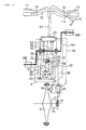
- Fig. 1 is a view showing a configuration of a motor-driven bicycle to which the present invention is applied.
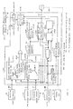
- Fig. 2 is a block diagram of a controller shown in FIG. 1.
- Fig. 3 is a flow chart showing an operation of the controller.
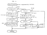
- Fig. 4 is a flow chart showing a rapid acceleration suppressing control.
- Fig. 5 is a flow chart showing a gear-shift control.
- Fig. 6 is a flow chart showing a motor output limiting control.
- Fig. 7 is a view showing a gear-shift control method upon shift-up from the "second speed” to the "third speed".
- Fig. 8 is a view showing a gear-shift control method upon shift-down from the "second speed" to the "first speed”.
- Fig. 9 is a view showing a gear-shift control method upon shift-up from the "first speed” to the "second speed”.
- Fig. 10 is aview showing a method of setting a gear-shift vehicle speed Vch23 between the "second speed” and the "third speed”.
- Fig. 11 is a view showing a method of setting a gear-shift vehicle speed Vchl2 between the "first speed” and the "second speed”.
- Fig. 12 is a block diagram of another embodiment of the controller shown in FIG. 1.
- FIG. 1 is a view showing a configuration of a motor-driven bicycle to which the present invention is applied. In this figure, parts not necessary for description of the present invention are omitted.
- a handlebar 10 Like a conventional bicycle, a handlebar 10 includes at its left end portion a brake lever 11 for a rear wheel and at its right end portion a brake lever 13 for a front wheel. The handlebar 10 also includes in the vicinities of fulcrums of the brake levers 11 and 13 brake switches 12 and 14 for detecting operational states of the brake levers 11 and 13 and outputting during-braking signals SB. The handlebar 10 further includes at its right end portion a throttle lever 16 as self-running input means for indicating generation of a self-running power to a drive motor M (which will be described later), and a throttle opening sensor 15 for detecting an operated angle ⁇ th as an operated amount.
- a body frame has at its central portion a power unit 2 for selectively carrying out "self-running” by the drive motor M and "assist-running” for assisting a leg power by a drive force of the drive motor M.
- a leg-power inputted to a crank shaft 30 from left and right crank pedals 38L and 38R is transmitted via a one-way clutch 26 to a large-diameter gear 36 coaxially connected to the crank shaft 30, and is further transmitted via a first idle shaft 35 to an output shaft 34.
- the one-way clutch 26 allows transmission of a rotational force from the crank shaft 30 to the large-diameter gear 36, and prohibits transmission of a rotational force from the large-diameter gear 36 to the crank shaft 30.
- a drive force generated by the drive motor M is transmitted via a second idle shaft 36 to an idle gear 37.
- the idle gear 37 is connected via a one-way clutch 29 to the first idle shaft 35.
- the drive force having been transmitted to the idle gear 37 is transmitted via the first idle shaft 35 to the output shaft 34.
- One end of the output shaft 34 is exposed to the outside of the power unit 2, and a drive sprocket 32 is connected to the exposed end of the output shaft 34.
- a motor rotation sensor 25 detects a rotational speed NM of the drive motor M.
- a temperature sensor 24 detects a temperature TM of the drive motor M.
- a leg-power sensor 23 detects a leg-power inputted to the crank shaft 30.
- a crank pedal rotation sensor 22 detects a rotational speed of the crank pedals 38 (38L, 38R) on the basis of the rotational speed of the large-diameter gear 36.
- a current sensor 27 detects a drive current IM of the drive motor M. Output signals of the above-described sensors are inputted to a controller 20.
- a driven sprocket 33 and a four-step gear shifter 19 are provided on an axle of a rear wheel 31 as a drive wheel.
- the drive sprocket 32 of the output shaft 34 is connected to the driven sprocket 33 via a chain 39.
- An automatic gear-shift actuator 17 outputs a gear-shift step signal DG representative of a gear-shift step in response to a gear-shift command SG outputted from the controller 20.
- the gear shifter 19 is driven on the basis of the gear-shift step signal DG.
- a rotational speed V of the rear wheel 31 is detected by a vehicle speed sensor 18, and a signal of the vehicle speed sensor 18 is inputted to the controller 20.
- FIG. 2 is a block diagram showing a configuration of a main portion of the controller 20.
- the same characters as those shown in FIG. 1 designate the same or similar parts.
- a reference duty ratio Drefl of a drive current IM to be supplied to the drive motor M upon self-running is previously registered in the form of a mapping table with the throttle opening angle ⁇ th detected by the throttle opening sensor 15, the vehicle speed V, and a gear step G taken as parameters.
- a reference duty ratio Dref2 of the drive current IM to be supplied to the drive motor M upon assist-running is previously registered in the form of a mapping table with the leg-power F detected by the leg-power sensor 23 and the vehicle speed V detected by the vehicle speed sensor 18 taken as parameters.
- the vehicle speed V may be detected, by a vehicle speed detecting portion 213 additionally provided, on the basis of the gear-shift step signal DG, which is representative of the gear-shift step G and which is outputted from the automatic gear-shift actuator 17, and the motor rotational speed.
- An acceleration detecting portion 203 detects an acceleration ⁇ V on the basis of a rate of change in vehicle speed V with elapsed time.
- a gear step deciding portion 204 decides the present gear step G on the basis of the detected vehicle speed V and motor rotational speed NM.
- a rapid acceleration suppressing control portion 205 compares the detected acceleration ⁇ V with a reference acceleration ⁇ Vref, and instructs, if the detected acceleration ⁇ V is more than the reference acceleration ⁇ Vref, a duty ratio correcting portion 208 (which will be described later) to correct a duty ratio so as to suppress rapid acceleration.
- a gear-shift control portion 206 decides, on the basis of the detected acceleration ⁇ V and vehicle speed V and the present gear step G decided by the gear step deciding portion 204, whether or not the present running state is a gear-shift timing state. The decided result is supplied to the duty ratio correcting portion 208 and is also outputted to the gear-shift actuator 17.
- a non-riding self-running deciding portion 207 decides, on the basis of the present gear step G and motor rotational speed NM, whether or not the present self-running operation is performed in the driver's non-riding state. If it is decided that the self-running operation is performed in the driver's non-riding state, a hand-pushing drive control portion 211 instructs the duty ratio correcting portion 208 to correct a duty ratio so as to generate a self-running power corresponding to a walking speed.
- a during-braking control portion 210 instructs the duty ratio correcting portion 208 to correct a duty ratio so as to control a self-running power on the basis of the presence or absence of a braking operation and the vehicle speed V.
- the during-braking control portion 210 instructs the duty ratio correcting portion 208 to correct a duty ratio so as to allow the drive motor M to generate a drive force being small enough to bring about a state in which no load is apparently applied to the drive motor M.
- the during-braking control portion 210 instructs the duty ratio correcting portion 208 to correct a duty ratio so as to allow the drive motor M to generate a drive force corresponding to an operated amount of the self-running operation.
- a motor output limiting portion 209 monitors an operational state of the drive motor M on the basis of the drive current IM of the drive motor M detected by the current sensor 27 and the temperature TM of the drive motor M detected by the temperature sensor 24, and instructs, if the drive motor M is in a severe operational state, the duty ratio correcting portion 208 to correct a duty ratio so as to limit the self-running power.
- the duty ratio correcting portion 208 corrects, as will be described in detail later, the reference duty ratio Dref1 or Dref2 obtained from the duty ratio map 201 or 202 on the basis of the instructions supplied from the rapid acceleration suppressing control portion 205, the gear-shift control portion 206, the hand-pushing control portion 211, the during-braking control portion 210, and the motor output limiting portion 209, and outputs the corrected result as a target duty ratio DM.
- step S11 an opening angle ⁇ th of the throttle lever 16 is detected as an operated amount of the self-running operation by the throttle opening sensor 15; a vehicle speed V is detected by a vehicle speed sensor 18; and a rotational speed NM of the drive motor M is detected by the motor rotation sensor 25.
- step S12 an acceleration ⁇ V is calculated on the basis of the vehicle speed V detected in step S11 by the acceleration detecting portion 203.
- step S13 the present gear step G is decided on the basis of a correlation between the vehicle speed V and the motor rotational speed NM by the gear step deciding portion 204. It should be noted that the present gear step G may be decided on the basis of the gear-shift step signal DG outputted from the automatic gear-shift actuator 17.
- step S14 a drive current IM of the drive motor M is detected by the current sensor 27, and a temperature TM of the drive motor M is detected by the temperature sensor 24.
- step S15 a reference duty ratio Drefl upon self-running is retrieved from the duty ratio map 201 for self-running on the basis of the throttle opening angle ⁇ th and vehicle speed V detected in step S11 and the present gear step G decided in step S13.
- step S16 on the basis of the states of the brake switches 12 and 14, it is decided by the during-braking control portion 210 whether or not a braking operation has been performed. If it is decided that the braking operation has not been performed, the process goes on to step S17.
- step S17 on the basis of an increase ratio ⁇ NM of the motor rotational speed NM, it is decided by the non-riding self-running deciding portion 207 whether or not the driver has operated the throttle lever 16 in the driver's non-riding state. If the increase ratio ⁇ NM of the motor rotational speed NM is a reference increase ratio ⁇ Nref or more, it is decided that the driver has operated the throttle lever 16 in the driver's non-riding state, and the process goes on to step S24. If the increase ratio ⁇ NM is less than the reference increase ratio ⁇ Nref, it is decided that the driver has operated the throttle lever 16 in the driver's riding state, and the process goes on to step S18.
- the parameter for deciding whether or not the driver has operated the throttle lever 16 in the driver's non-riding state is not limited to the above-described increase ratio ⁇ NM of the motor rotational speed NM.
- the acceleration ⁇ V may be used as the decision parameter. In this case, if the acceleration ⁇ V is larger than a reference acceleration, it may be decided that the driver has operated the throttle lever 16 in the driver's non-riding state.
- a change ratio of the drive current of the drive motor M may be used as the decision parameter. In this case, if the change ratio of current is larger than a reference change ratio of current, it may be decided that the driver has operated the throttle lever 16 in the driver's non-riding state.
- step S18 a routine of "rapid acceleration suppressing control" for ensuring a sufficient acceleration performance while suppressing rapid acceleration is executed.
- FIG. 4 is a flow chart indicating a control content of the "rapid acceleration suppressing control".
- the control content is determined such that an acceleration corresponding to an operated amount of the throttle lever 16 can be obtained irrespective of a road surface state, a deadweight, and the like by controlling a self-running power of the drive motor M on the basis of a correlation between an operated amount of the throttle lever 16 and an acceleration.
- step S181 the present acceleration ⁇ V is compared with a reference acceleration ⁇ Vref by the rapid acceleration suppressing control portion 205. If the acceleration ⁇ V is more than the reference acceleration ⁇ Vref, it is decided that the vehicle is in the rapid acceleration state, and the process goes on to step S182.
- step S182 the reference duty ratio Dref1 retrieved from the duty ratio map 201 upon self-running is multiplied by a correction coefficient smaller than "1" by the duty ratio correcting portion 208, and the calculated result is taken as a target duty ratio DM.
- the correction coefficient is defined as "0.9 k1 ", and the initial value of the exponent kl is set to "1". Accordingly, in the initial state, a value being 0.9 times the reference duty ratio Dref1 decided by the map 201 is registered as the target duty ratio DM. In step S183, the value of the exponent kl is incremented by "1". In step S184, a rapid acceleration suppressing flag F1 is set to "1".
- step S181 since the above steps are repeated to increase the value of the exponent k1 until it is decided in step S181 that the acceleration ⁇ V is less than the reference acceleration ⁇ Vref, the target duty ratio DM is gradually reduced depending on the value of the exponent k1.
- step S181 If it is decided in step S181, as a result of gradually reducing the target duty ratio DM, that the acceleration ⁇ V is less than the reference acceleration ⁇ Vref, the process goes on to step S185 in which it is decided that the rapid acceleration suppressing flag F1 is "1". If it is decided that the flag F1 is set to "1", the process goes on to step S186 in which the duty ratio having been gradually reduced in step S182 is gradually increased.
- step S186 the present target duty ratio DM is multiplied by a correction coefficient smaller than "1", and the calculated result is taken as a new target duty ratio DM.
- step S187 it is decided whether or not the exponent k2 is reduced to "0". Since the exponent k2 is "5" in the initial state, the process goes on to step S188. In step S188, the value of the exponent k2 is decremented by "1". If it is decided in step S187 that the exponent k2 is "0", the process goes on to step S189 in which the rapid acceleration suppressing flag F1 is reset, thereby ending the routine of "rapid acceleration suppressing control" shown in FIG. 4.
- the correction coefficient is, in step S182, gradually reduced for gradually reducing the target duty ratio DM, and thereafter, if the acceleration ⁇ V is less than the reference acceleration ⁇ Vref, the correction coefficient is, in step S186, gradually increased for gradually increasing the target duty ratio DM, thereby compensating for the above-described gradually reduced amount of the target duty ratio DM. Accordingly, it is possible to obtain a sufficient acceleration performance while suppressing rapid acceleration.
- step S19 it is decided by the gear-shift control portion 206 whether or not automatic gear-shift should be performed. If an absolute value of a difference between the present vehicle speed V and a gear-shift vehicle speed Vch stored in the gear-shift vehicle speed data table 206a for each gear step is less than a reference speed VA, the process goes on to step S20 in which a "gear-shift control" is executed for automatic gear-shift.
- gear-shift vehicle speed Vch As the gear-shift vehicle speed Vch, a gear-shift vehicle speed Vch12 indicating a gear-shift timing between "first speed”/ "second speed”, a gear-shift vehicle speed Vch23 indicating a gear-shift timing between “second speed”/ “third speed”, and a gear-shift vehicle speed Vch34 indicating a gear-shift timing between "third speed”/"fourth speed” are registered. Either of the gear-shift vehicle speeds Vch12, Vch23, and Vch34 is selected on the basis of the present gear step G.
- FIG. 5 is a flow chart indicating the routine of the "gear-shift control", which mainly shows the operation of the gear-shift control portion 206.
- step S201 it is decided whether or not a variation in torque caused by gear-shift is increased or decreased. For example, upon shift-up from the "second speed” to the "third speed”, as shown in FIG. 7, a torque at the "third speed” is larger than that of the "second speed” at the gear-shift vehicle speed Vch23, and accordingly, it is decided in step S201 that the torque is increased after gear-shift, and the process goes on to step S202. Similarly, upon shift-down from the "second speed” to the "first speed”, as shown in FIG. 8, a torque at the "first speed” is larger than that of the "second speed” at the gear-shift vehicle speed Vchl2, and accordingly, it is decided in step S201 that the torque is increased after gear-shift, and the process goes on to step S202.
- step S202 referring to the gear-shift vehicle speed data table 206a, the gear-shift control portion 206 decides whether or not the present vehicle speed V reaches a predetermined gear-shift vehicle speed Vch corresponding to the present gear step.
- the process goes on to step S203 in which the gear-shift actuator 17 is driven for gear-shift (shift-up).
- step S204 the present target duty ratio DM is multiplied by a correction coefficient smaller than "1", and the calculated result is taken as a new target duty ratio DM.
- step S205 it is decided whether or not the exponent k3 is "0". Since the exponent k3 is "5" in the initial state, the process goes on to step S207 in which the exponent k3 is decremented by "1".
- the target duty ratio DM is reduced such that a torque immediately after shift-down to the "first speed” is reduced to the same level as that of a torque at the "second speed”, and then the target duty ratio DM is gradually increased to be returned to the original target duty ratio DM, thereby obtaining a desirable shift feeling.
- step S201 since a torque at the "second speed” is smaller than a torque at the "first speed” at the gear-shift vehicle speed Vch12, it is decided in step S201 that the torque is reduced after gear-shift, and the process goes on to step S208 in which it is decided whether or not the present vehicle speed V reaches a predetermined gear-shift vehicle speed Vch12. If it is decided that the vehicle speed does not reach the gear-shift vehicle speed Vch12, the process goes on to step S209 in which the present target duty ratio DM is multiplied by a correction coefficient smaller than "1" and the calculated result is taken as a new target duty ratio DM.
- the correction coefficient is defined as "0.9 k4 ", and the initial value of the exponent k4 is set to "1". Accordingly, in the initial state, a value being 0.9 times the present target duty ratio DM is taken as a target duty ratio. In step S210, the exponent k4 is incremented by "1".
- step S208 the vehicle speed V reaches the gear-shift vehicle speed Vch12, whereby the target duty ratio DM is gradually reduced according to the value of the exponent k4. Accordingly, as shown in FIG. 9, the torque is gradually reduced.
- step S208 If it is decided in step S208 that the vehicle speed V reaches the gear-shift vehicle speed Vch12, the process goes on to step S211 in which the gear-shift actuator is driven for gear-shift.
- step S211 since a torque at the "first speed” is reduced to the same level as that of a torque at the "second speed” as shown in FIG. 9, that is, no difference in output torque lies between before and after gear-shift, it is possible to obtain a desirable shift feeling.
- step S212 the exponent k4 is set to "1", thereby completing the routine of the "gear-shift control" shown in FIG. 5.
- the gear-shift vehicle speed Vch typically, Vch12 or Vch23 may be set to a speed at which torque curves of adjacent two of gear steps before and after gear-shift intersect each other, or a neighborhood of the speed. With this configuration, it is also possible to improve the shift feeling upon gear-shift.
- step S23 a routine of "motor output limiting control" for preventing a severe operation of the drive motor is executed.
- the "motor output limiting control” will be described below with reference to a flow chart shown in FIG. 6.
- step S231 on the basis of a motor drive current IM detected by the current sensor 27 and the present target duty ratio DM, the present output Pout of the drive motor M is calculated.
- step S232 the present output Pout of the drive motor M is compared with a specific maximum output Pmax.
- the maximum output Pmax is preferably set to a value being about two times the maximum rating of the drive motor M and is, in this embodiment, set to a value being 1.5 times the maximum rating.
- step S232 if it is decided in step S232 that the present output Pout is equal to or more than the maximum output Pmax, the process goes on to step S233 in which the target duty ratio DM is set to a specific maximum value Dmax.
- step S234 a temperature TM of the drive motor M detected by the temperature sensor 24 is compared with a reference temperature Tref.
- the reference temperature Tref is set to 90°C.
- step S235 in which the present target duty ratio DM is multiplied by a correction coefficient smaller than "1" and the calculated result is taken as a new target duty ratio DM.
- the correction coefficient is defined as "0.5 k5 ", and the initial value of the exponent k5 is set to "1". Accordingly, a value being 0.5 times the present target duty ratio DM is taken as a target duty ratio DM.
- step S236, the exponent k5 is incremented by "1".
- step S234 if it is decided in step S234 that the temperature TM is less than the reference temperature Tref, the process goes on to step S236 in which the exponent k5 is set to the initial value "1".
- the output of the drive motor M is limited and also if the temperature of the drive motor M is increased, the target duty ratio DM is gradually reduced, it is possible to prevent a severe operation of the drive motor M. Also, since the upper limit of the output of the drive motor M lies within a range being two times the rating of the drive motor M, it is possible to obtain a self-running power from the drive motor M without a severe operation of the drive motor M.
- step S25 a control of a current of the drive motor M based on the target duty ratio thus determined is executed.
- step S16 determines whether or not either of the brake switches 12 and 14 is in the on-state, that is, the vehicle is on braking.
- step S21 it is decided, on the basis of the vehicle speed V, whether or not the vehicle is on running.
- step S21 if the vehicle speed V is larger than "0", it is decided in step S21 that the vehicle is on running, and the process goes on to step S22.
- step S22 a value being 20% (or which may be 0%) of the present target duty ratio DM, or a value being 20% (or which may be 0%) of the maximum value Dmax of the target duty ratio is set as a target duty ratio DM for allowing the drive motor M to generate a drive force being small enough to bring about a state in which no load is apparently applied to the drive motor M.
- step S21 If it is decided in step S21 that the vehicle is on stoppage, the process goes on to step S186 of the above-described routine of "rapid acceleration suppressing control" shown in FIG. 4. As a result, the target duty ratio DM is rapidly reduced, and then gradually increased.
- a self-running power to be generated by the drive motor is gradually increased to a value corresponding to an operated amount of self-running, it is possible to prevent "slip-down" of the vehicle upon start-up of the vehicle on a slope.
- step S17 It is decided in step S17 that the vehicle is in the driver's non-riding state, the process goes on to step S24.
- step S24 to allow the drive motor M to generate a self-running power optimum for hand-pushing drive of the vehicle, a value being 20% of the present target duty ratio DM, or a value being 20% of the maximum value Dmax of the target duty ratio is set as a new target duty ratio DM.
- the motor-drive bicycle in this embodiment is allowed to achieve a self-running function matched to a walking speed without provision of a plurality of self-running operation input means.
- a self-running operation is performed in the driver's non-riding state, and a self-running power matched to a walking speed is generated only when it is decided that the self-running operation is performed in the driver's non-riding state, and accordingly, it is possible to eliminate an inconvenience that a self-running power matched to a walking speed is outputted in the driver's riding state.
- the rotational speed of the drive wheel 31 is directly detected by the vehicle speed sensor 18 and the vehicle speed V is detected on the basis of the rotational speed of the drive wheel 31; however, the present invention is not limited thereto.
- the vehicle speed V may be calculated on the basis of the rotational speed NM of the drive motor M detected by the motor rotation sensor 25 and the gear step G.
- the vehicle speed V may be calculated on the basis of the rotational speed of the crank pedals 38 detected by the crank pedal rotation sensor 22 and the gear step G.
- the reference duty ratio Drefl of the drive current IM to be supplied to the drive motor M during self-running is registered, in the self-running reference duty ratio map 201, as the function of the throttle opening angle ⁇ th, the vehicle speed V, and the gear step G; however, the present invention is not limited thereto.
- the reference duty ratio Drefl and the throttle opening angle ⁇ th may be registered, as a map, in the self-running reference duty ratio map 201, and the reference duty ratio Drefl retrieved on the basis of the throttle opening angle ⁇ th may be suitably corrected on the basis of the vehicle speed V and the gear step G by the correcting portion 213.
- the invention provides a motor-driven bicycle including an automatic gear shifter, which is capable of improving a shift feeling upon gear-shift and controlling a self-running power of a drive motor determined on the basis of an amount of a self-running operation by a driver as a function of a braking state and a vehicle speed.
- a motor-driven bicycle includes a drive motor M for generating a self-running power in response to a self-running operation by a driver, a gear shifter connected between the drive motor M and a drive wheel, and means for detecting a vehicle speed.
- This motor-driven bicycle further includes a self-running reference duty ratio map 201 for determining a self-running power to be generated by the drive motor M, that is, a duty ratio of an AC exciting current to be supplied to the drive motor M on the basis of an operated amount of a self-running operation by a driver, a gear step of the gear shifter, and a vehicle speed.
- a self-running reference duty ratio map 201 a reference duty ratio Drefl of a drive current to be supplied to the drive motor M at the time of self-running is previously registered as a function of a throttle angle ⁇ th detected by a throttle opening sensor 15.
- a during-braking control portion 210 decides whether or not braking operation is performed on the basis of the states of brake switches 12 and 14, and receives a vehicle speed V detected by a vehicle speed sensor 18.
- a duty ratio correcting portion 208 corrects the reference duty ratio Drefl obtained from the duty ratio map 201 on the basis of a control signal from the during-braking control portion 210.
Landscapes
- Engineering & Computer Science (AREA)
- Chemical & Material Sciences (AREA)
- Combustion & Propulsion (AREA)
- Transportation (AREA)
- Mechanical Engineering (AREA)
- Power Engineering (AREA)
- Electric Propulsion And Braking For Vehicles (AREA)
- Control Of Transmission Device (AREA)
- Connection Of Motors, Electrical Generators, Mechanical Devices, And The Like (AREA)
- Control Of Driving Devices And Active Controlling Of Vehicle (AREA)
- Memory System Of A Hierarchy Structure (AREA)
- Vehicle Body Suspensions (AREA)
Applications Claiming Priority (2)
| Application Number | Priority Date | Filing Date | Title |
|---|---|---|---|
| JP2000055085 | 2000-03-01 | ||
| JP2000055085A JP4369589B2 (ja) | 2000-03-01 | 2000-03-01 | 電動自転車 |
Publications (3)
| Publication Number | Publication Date |
|---|---|
| EP1129932A2 true EP1129932A2 (de) | 2001-09-05 |
| EP1129932A3 EP1129932A3 (de) | 2004-05-19 |
| EP1129932B1 EP1129932B1 (de) | 2005-05-18 |
Family
ID=18576263
Family Applications (1)
| Application Number | Title | Priority Date | Filing Date |
|---|---|---|---|
| EP01103471A Expired - Lifetime EP1129932B1 (de) | 2000-03-01 | 2001-02-14 | Antriebseinheit für Fahrräder |
Country Status (7)
| Country | Link |
|---|---|
| EP (1) | EP1129932B1 (de) |
| JP (1) | JP4369589B2 (de) |
| CN (2) | CN100430288C (de) |
| AT (1) | ATE295801T1 (de) |
| DE (1) | DE60110853T2 (de) |
| ES (1) | ES2241698T3 (de) |
| TW (1) | TW550205B (de) |
Cited By (16)
| Publication number | Priority date | Publication date | Assignee | Title |
|---|---|---|---|---|
| EP1457415A3 (de) * | 2003-03-11 | 2005-04-06 | Shimano Inc. | Steuerungseinrichtung für eine Fahrradgangschaltung mit reduziertem Kraftaufwand beim Schalten |
| FR2891801A1 (fr) * | 2005-10-10 | 2007-04-13 | Jjg Partenaires Eurl Sarl | Velo electrique |
| WO2011154657A1 (fr) * | 2010-06-11 | 2011-12-15 | Starway | Dispositif de regulation de l'assistance electrique d'un velo |
| EP2476575A1 (de) * | 2011-01-14 | 2012-07-18 | Pro-Movec A/S | Antriebssteuerung eines elektrisch motorisierten Motorrads |
| EP2511166A1 (de) * | 2011-04-13 | 2012-10-17 | J.D Components Co., Ltd. | Verschiebungssteuerungssystem für ein stromunterstütztes Fahrrad |
| EP2540606A1 (de) * | 2011-06-30 | 2013-01-02 | Fritz U. Bankwitz | Vorrichtung zur Einstellung wenigstens einer Fahrzeugfunktion eines Zweiradfahrzeugs |
| WO2013041276A3 (de) * | 2011-09-20 | 2013-05-30 | Robert Bosch Gmbh | Verfahren zum automatischen ansteuern des elektromotors eines fahrrads und entsprechende steuervorrichtung |
| EP2862788A1 (de) * | 2013-10-16 | 2015-04-22 | Conti Temic microelectronic GmbH | Steuereinheit zur Verwendung in einem von einem Fahrer antreibbaren Fortbewegungsmittel |
| EP2862789A1 (de) * | 2013-10-16 | 2015-04-22 | Conti Temic microelectronic GmbH | Steuereinheit zur Verwendung in einem von einem Fahrer antreibbaren Fortbewegungsmittel |
| WO2015073791A1 (en) | 2013-11-15 | 2015-05-21 | Robert Bosch Gmbh | Automatic gear shift system for an e-bicycle |
| US20160052594A1 (en) * | 2013-04-08 | 2016-02-25 | Robert Bosch Gmbh | Pedal-driven vehicle, and method for operating the pedal-driven vehicle |
| EP3256373A4 (de) * | 2015-02-13 | 2018-10-31 | Civilized Cycles Incorporated | Systeme, verfahren und vorrichtungen für getriebe eines elektrischen fahrrads |
| EP3564111A4 (de) * | 2016-12-28 | 2020-01-15 | Yamaha Hatsudoki Kabushiki Kaisha | Elektrisches unterstützungssystem und elektrisch unterstütztes fahrzeug |
| CN112918272A (zh) * | 2019-12-06 | 2021-06-08 | 博世汽车部件(苏州)有限公司 | 电机控制方法、电机控制装置和载具 |
| NO346194B1 (en) * | 2021-01-14 | 2022-04-11 | Ca Tech Systems As | Pedally propelled vehicle gear system and method for operating such system |
| CN115258025A (zh) * | 2019-12-18 | 2022-11-01 | 株式会社岛野 | 人力驱动车用控制装置及动力传递系统 |
Families Citing this family (25)
| Publication number | Priority date | Publication date | Assignee | Title |
|---|---|---|---|---|
| JP2003231491A (ja) * | 2002-02-08 | 2003-08-19 | Sunstar Eng Inc | 有酸素運動を可能とする電動アシスト自転車 |
| US7247108B2 (en) * | 2002-05-14 | 2007-07-24 | Shimano, Inc. | Method and apparatus for controlling an automatic bicycle transmission |
| JP3675431B2 (ja) * | 2002-10-01 | 2005-07-27 | 松下電器産業株式会社 | 電動機駆動装置 |
| CN101377685B (zh) * | 2007-08-28 | 2012-03-28 | 比亚迪股份有限公司 | 用于电动汽车的智能防撞系统 |
| JP5247863B2 (ja) * | 2011-08-29 | 2013-07-24 | 株式会社シマノ | 自転車用制御装置 |
| DE102011084931A1 (de) * | 2011-10-21 | 2013-04-25 | Zf Friedrichshafen Ag | Fahrrad mit einem Zusatzantrieb |
| US9394030B2 (en) | 2012-09-27 | 2016-07-19 | Sram, Llc | Rear derailleur |
| JP5607225B1 (ja) | 2013-09-04 | 2014-10-15 | 株式会社シマノ | 自転車用制御装置 |
| TWI508893B (zh) * | 2013-09-25 | 2015-11-21 | Cycling & Health Tech Ind R&D | Intelligent variable speed control system |
| TWI619639B (zh) * | 2014-04-15 | 2018-04-01 | Motive Power Industry Co Ltd | Stepless speed change system and automatic control method thereof |
| JP6636732B2 (ja) * | 2015-06-30 | 2020-01-29 | 株式会社シマノ | 自転車の制御システム |
| DE102016209275B3 (de) * | 2016-05-30 | 2017-09-28 | Robert Bosch Gmbh | Steuerungsverfahren und Vorrichtungen zur Steuerung des Elektromotors eines Elektrofahrrads |
| DE102016209570B3 (de) * | 2016-06-01 | 2017-08-24 | Robert Bosch Gmbh | Steuerungsverfahren und Steuergerät zur Anpassung einer Geschwindigkeit der Schiebehilfe eines Elektrofahrrads |
| JP7045238B2 (ja) * | 2018-03-29 | 2022-03-31 | 株式会社シマノ | 人力駆動車用制御装置 |
| JP7514605B2 (ja) * | 2019-05-17 | 2024-07-11 | 株式会社シマノ | 人力駆動車用の制御装置 |
| JP7386439B2 (ja) * | 2019-12-10 | 2023-11-27 | パナソニックIpマネジメント株式会社 | 電動自転車用制御装置及び電動自転車 |
| CN111452628A (zh) * | 2020-03-31 | 2020-07-28 | 江苏金丰机电有限公司 | 一种大功率电动三轮车控制器防溜坡方法 |
| TWI766369B (zh) * | 2020-09-18 | 2022-06-01 | 光陽工業股份有限公司 | 電動機車的檔位變換系統及方法 |
| CN117295655A (zh) | 2021-05-11 | 2023-12-26 | 本田技研工业株式会社 | 车辆、通知方法、通知程序、存储介质及通知装置 |
| DE102021213526A1 (de) | 2021-11-30 | 2023-06-01 | Robert Bosch Gesellschaft mit beschränkter Haftung | Verfahren zum Betreiben eines Elektrofahrrads |
| GB2633795A (en) * | 2023-09-21 | 2025-03-26 | Jaguar Land Rover Ltd | Control system for a powertrain of a vehicle |
| DE102023210334A1 (de) | 2023-10-19 | 2025-04-24 | Robert Bosch Gesellschaft mit beschränkter Haftung | Verfahren und Einrichtung zur Überlastvermeidung bei einem Antrieb eines Elektrofahrrades |
| DE102024200066B3 (de) * | 2024-01-04 | 2025-05-15 | Zf Friedrichshafen Ag | Verfahren und Steuereinrichtung zum Steuern eines Antriebsmotors eines muskelkraftbetriebenen Fahrzeugs |
| DE102024200067B3 (de) * | 2024-01-04 | 2025-05-15 | Zf Friedrichshafen Ag | Verfahren und Steuereinrichtung zum Steuern eines Antriebsmotors eines muskelkraftbetriebenen Fahrzeugs |
| KR102951864B1 (ko) * | 2024-01-11 | 2026-04-13 | 에이치엘만도 주식회사 | 전기 이동수단의 출발 제어 방법 및 시스템 |
Citations (1)
| Publication number | Priority date | Publication date | Assignee | Title |
|---|---|---|---|---|
| JPH09263289A (ja) | 1996-03-29 | 1997-10-07 | Yamaha Motor Co Ltd | ペダル付電動車両 |
Family Cites Families (16)
| Publication number | Priority date | Publication date | Assignee | Title |
|---|---|---|---|---|
| DE3623800A1 (de) * | 1985-10-24 | 1987-04-30 | Binder Aviat Gmbh | Fahrrad mit zuschaltbarem motorantrieb |
| JP3138014B2 (ja) * | 1991-07-15 | 2001-02-26 | ヤマハ発動機株式会社 | 電動二輪車用の電動機制御装置 |
| JP3468799B2 (ja) * | 1993-06-18 | 2003-11-17 | ヤマハ発動機株式会社 | 電動モータ付き乗り物およびその制御方法 |
| JP3515156B2 (ja) * | 1994-01-31 | 2004-04-05 | 三洋電機株式会社 | 電気自転車 |
| JPH09123980A (ja) * | 1995-10-31 | 1997-05-13 | Suzuki Motor Corp | 電動自転車 |
| JP3640222B2 (ja) * | 1996-03-11 | 2005-04-20 | ヤマハ発動機株式会社 | 電動補助車両の補助力制御装置 |
| JP3810130B2 (ja) * | 1996-04-19 | 2006-08-16 | ヤマハ発動機株式会社 | 電動モータ付き乗り物およびその制御方法 |
| JPH09308007A (ja) * | 1996-05-08 | 1997-11-28 | Toyota Motor Corp | ハイブリッド車両の制御装置 |
| JP3682590B2 (ja) * | 1996-05-24 | 2005-08-10 | ソニー株式会社 | 移動装置と移動制御方法 |
| JP3539075B2 (ja) * | 1996-06-14 | 2004-06-14 | トヨタ自動車株式会社 | ハイブリッド車両の駆動制御装置 |
| JP3296729B2 (ja) * | 1996-08-23 | 2002-07-02 | 本田技研工業株式会社 | 交流モータ制御装置 |
| US5937964A (en) * | 1997-03-18 | 1999-08-17 | Currie Technologies Incorporated | Unitary power module for electric bicycles, bicycle combinations and vehicles |
| JP3952541B2 (ja) * | 1997-06-03 | 2007-08-01 | スズキ株式会社 | 二輪車用アシスト装置 |
| CN2319256Y (zh) * | 1997-11-13 | 1999-05-19 | 高天海 | 内装电池电动自行车 |
| JPH11227663A (ja) * | 1998-02-19 | 1999-08-24 | Yamaha Motor Co Ltd | 二輪車 |
| JP2000289682A (ja) * | 1999-04-12 | 2000-10-17 | Suzuki Motor Corp | 電動自転車 |
-
2000
- 2000-03-01 JP JP2000055085A patent/JP4369589B2/ja not_active Expired - Lifetime
-
2001
- 2001-02-14 EP EP01103471A patent/EP1129932B1/de not_active Expired - Lifetime
- 2001-02-14 AT AT01103471T patent/ATE295801T1/de not_active IP Right Cessation
- 2001-02-14 ES ES01103471T patent/ES2241698T3/es not_active Expired - Lifetime
- 2001-02-14 DE DE60110853T patent/DE60110853T2/de not_active Expired - Fee Related
- 2001-02-26 TW TW090104302A patent/TW550205B/zh not_active IP Right Cessation
- 2001-02-28 CN CNB031239285A patent/CN100430288C/zh not_active Expired - Fee Related
- 2001-02-28 CN CNB011109033A patent/CN1241783C/zh not_active Expired - Fee Related
Patent Citations (1)
| Publication number | Priority date | Publication date | Assignee | Title |
|---|---|---|---|---|
| JPH09263289A (ja) | 1996-03-29 | 1997-10-07 | Yamaha Motor Co Ltd | ペダル付電動車両 |
Cited By (21)
| Publication number | Priority date | Publication date | Assignee | Title |
|---|---|---|---|---|
| US7062980B2 (en) | 2003-03-11 | 2006-06-20 | Shimano, Inc. | Bicycle shift control device with decreased stress during shifting |
| EP1457415A3 (de) * | 2003-03-11 | 2005-04-06 | Shimano Inc. | Steuerungseinrichtung für eine Fahrradgangschaltung mit reduziertem Kraftaufwand beim Schalten |
| FR2891801A1 (fr) * | 2005-10-10 | 2007-04-13 | Jjg Partenaires Eurl Sarl | Velo electrique |
| WO2011154657A1 (fr) * | 2010-06-11 | 2011-12-15 | Starway | Dispositif de regulation de l'assistance electrique d'un velo |
| FR2961166A1 (fr) * | 2010-06-11 | 2011-12-16 | Starway | Dispositif de regulation de l'assistance electrique d'un velo |
| EP2476575A1 (de) * | 2011-01-14 | 2012-07-18 | Pro-Movec A/S | Antriebssteuerung eines elektrisch motorisierten Motorrads |
| WO2012095528A3 (en) * | 2011-01-14 | 2012-12-27 | Pro-Movec A/S | Drive control of an electrically motorised bicycle |
| EP2511166A1 (de) * | 2011-04-13 | 2012-10-17 | J.D Components Co., Ltd. | Verschiebungssteuerungssystem für ein stromunterstütztes Fahrrad |
| EP2540606A1 (de) * | 2011-06-30 | 2013-01-02 | Fritz U. Bankwitz | Vorrichtung zur Einstellung wenigstens einer Fahrzeugfunktion eines Zweiradfahrzeugs |
| WO2013041276A3 (de) * | 2011-09-20 | 2013-05-30 | Robert Bosch Gmbh | Verfahren zum automatischen ansteuern des elektromotors eines fahrrads und entsprechende steuervorrichtung |
| US20160052594A1 (en) * | 2013-04-08 | 2016-02-25 | Robert Bosch Gmbh | Pedal-driven vehicle, and method for operating the pedal-driven vehicle |
| EP2862788A1 (de) * | 2013-10-16 | 2015-04-22 | Conti Temic microelectronic GmbH | Steuereinheit zur Verwendung in einem von einem Fahrer antreibbaren Fortbewegungsmittel |
| EP2862789A1 (de) * | 2013-10-16 | 2015-04-22 | Conti Temic microelectronic GmbH | Steuereinheit zur Verwendung in einem von einem Fahrer antreibbaren Fortbewegungsmittel |
| WO2015073791A1 (en) | 2013-11-15 | 2015-05-21 | Robert Bosch Gmbh | Automatic gear shift system for an e-bicycle |
| EP3068683A4 (de) * | 2013-11-15 | 2017-07-05 | Robert Bosch GmbH | Schaltsystem für automatikgetriebe eines elektrofahrrads |
| EP3256373A4 (de) * | 2015-02-13 | 2018-10-31 | Civilized Cycles Incorporated | Systeme, verfahren und vorrichtungen für getriebe eines elektrischen fahrrads |
| US10358133B2 (en) | 2015-02-13 | 2019-07-23 | Civilized Cycles Incorporated | Electric bicycle transmission systems, methods, and devices |
| EP3564111A4 (de) * | 2016-12-28 | 2020-01-15 | Yamaha Hatsudoki Kabushiki Kaisha | Elektrisches unterstützungssystem und elektrisch unterstütztes fahrzeug |
| CN112918272A (zh) * | 2019-12-06 | 2021-06-08 | 博世汽车部件(苏州)有限公司 | 电机控制方法、电机控制装置和载具 |
| CN115258025A (zh) * | 2019-12-18 | 2022-11-01 | 株式会社岛野 | 人力驱动车用控制装置及动力传递系统 |
| NO346194B1 (en) * | 2021-01-14 | 2022-04-11 | Ca Tech Systems As | Pedally propelled vehicle gear system and method for operating such system |
Also Published As
| Publication number | Publication date |
|---|---|
| TW550205B (en) | 2003-09-01 |
| CN1515451A (zh) | 2004-07-28 |
| DE60110853T2 (de) | 2005-11-17 |
| JP2001239982A (ja) | 2001-09-04 |
| DE60110853D1 (de) | 2005-06-23 |
| CN100430288C (zh) | 2008-11-05 |
| CN1241783C (zh) | 2006-02-15 |
| CN1311128A (zh) | 2001-09-05 |
| JP4369589B2 (ja) | 2009-11-25 |
| EP1129932A3 (de) | 2004-05-19 |
| ES2241698T3 (es) | 2005-11-01 |
| EP1129932B1 (de) | 2005-05-18 |
| ATE295801T1 (de) | 2005-06-15 |
Similar Documents
| Publication | Publication Date | Title |
|---|---|---|
| EP1129932B1 (de) | Antriebseinheit für Fahrräder | |
| EP1129933B1 (de) | Antriebseinheit für Fahrräder | |
| EP1129934B1 (de) | Antriebseinheit für Fahrräder | |
| JP3654868B2 (ja) | 自転車用変速制御装置及び自転車用変速制御方法 | |
| JP3644633B2 (ja) | 自転車用変速制御装置 | |
| JP3736157B2 (ja) | 電動補助自転車 | |
| EP2377713A1 (de) | Fahrrad mit elektrischem Hilfsmotor | |
| US12139234B2 (en) | Method for controlling an electric drive motor of an electrically drivable bicycle | |
| US10179625B2 (en) | Electrically assisted bicycle | |
| EP3533700B1 (de) | Unterstützungskraftberechnungsverfahren für ein elektrisch unterstütztes fahrrad, elektrisch unterstützte fahrradsteuereinheit, elektrisch unterstützte fahrradantriebseinheit und elektrisch unterstütztes fahrrad | |
| US20240262456A1 (en) | Method for Operating a Drive System of an Electric Bike | |
| JP4509282B2 (ja) | 電動自転車 | |
| JP2000118481A (ja) | 電動アシスト自転車 | |
| JP4514072B2 (ja) | 電動自転車 | |
| JPH10114293A (ja) | 電動補助動力装置付自転車 | |
| JP3327181B2 (ja) | 電気自転車 | |
| JPH1159558A (ja) | 電動補助自転車 | |
| JP2001270486A (ja) | 電動モータ付き乗り物およびその制御方法 | |
| US20260097826A1 (en) | Method for Automatically Shifting into a Suitable Gear for Start-Up, Control Device, Computer Program Product, Computer-Readable Medium, Bicycle | |
| TWM680784U (zh) | 用於電動輔助自行車的輔助系統 | |
| JP2005048962A (ja) | 自転車用変速制御装置 |
Legal Events
| Date | Code | Title | Description |
|---|---|---|---|
| PUAI | Public reference made under article 153(3) epc to a published international application that has entered the european phase |
Free format text: ORIGINAL CODE: 0009012 |
|
| AK | Designated contracting states |
Kind code of ref document: A2 Designated state(s): AT BE CH CY DE DK ES FI FR GB GR IE IT LI LU MC NL PT SE TR |
|
| AX | Request for extension of the european patent |
Free format text: AL;LT;LV;MK;RO;SI |
|
| PUAL | Search report despatched |
Free format text: ORIGINAL CODE: 0009013 |
|
| AK | Designated contracting states |
Kind code of ref document: A3 Designated state(s): AT BE CH CY DE DK ES FI FR GB GR IE IT LI LU MC NL PT SE TR |
|
| AX | Request for extension of the european patent |
Extension state: AL LT LV MK RO SI |
|
| 17P | Request for examination filed |
Effective date: 20040525 |
|
| 17Q | First examination report despatched |
Effective date: 20040621 |
|
| GRAP | Despatch of communication of intention to grant a patent |
Free format text: ORIGINAL CODE: EPIDOSNIGR1 |
|
| AKX | Designation fees paid |
Designated state(s): AT BE CH CY DE DK ES FI FR GB GR IE IT LI LU MC NL PT SE TR |
|
| GRAS | Grant fee paid |
Free format text: ORIGINAL CODE: EPIDOSNIGR3 |
|
| GRAA | (expected) grant |
Free format text: ORIGINAL CODE: 0009210 |
|
| AK | Designated contracting states |
Kind code of ref document: B1 Designated state(s): AT BE CH CY DE DK ES FI FR GB GR IE IT LI LU MC NL PT SE TR |
|
| PG25 | Lapsed in a contracting state [announced via postgrant information from national office to epo] |
Ref country code: AT Free format text: LAPSE BECAUSE OF FAILURE TO SUBMIT A TRANSLATION OF THE DESCRIPTION OR TO PAY THE FEE WITHIN THE PRESCRIBED TIME-LIMIT Effective date: 20050518 Ref country code: BE Free format text: LAPSE BECAUSE OF FAILURE TO SUBMIT A TRANSLATION OF THE DESCRIPTION OR TO PAY THE FEE WITHIN THE PRESCRIBED TIME-LIMIT Effective date: 20050518 Ref country code: FI Free format text: LAPSE BECAUSE OF FAILURE TO SUBMIT A TRANSLATION OF THE DESCRIPTION OR TO PAY THE FEE WITHIN THE PRESCRIBED TIME-LIMIT Effective date: 20050518 |
|
| REG | Reference to a national code |
Ref country code: GB Ref legal event code: FG4D |
|
| REG | Reference to a national code |
Ref country code: CH Ref legal event code: EP |
|
| REG | Reference to a national code |
Ref country code: IE Ref legal event code: FG4D |
|
| REF | Corresponds to: |
Ref document number: 60110853 Country of ref document: DE Date of ref document: 20050623 Kind code of ref document: P |
|
| REG | Reference to a national code |
Ref country code: CH Ref legal event code: NV Representative=s name: A. BRAUN, BRAUN, HERITIER, ESCHMANN AG PATENTANWAE |
|
| PG25 | Lapsed in a contracting state [announced via postgrant information from national office to epo] |
Ref country code: SE Free format text: LAPSE BECAUSE OF FAILURE TO SUBMIT A TRANSLATION OF THE DESCRIPTION OR TO PAY THE FEE WITHIN THE PRESCRIBED TIME-LIMIT Effective date: 20050818 Ref country code: DK Free format text: LAPSE BECAUSE OF FAILURE TO SUBMIT A TRANSLATION OF THE DESCRIPTION OR TO PAY THE FEE WITHIN THE PRESCRIBED TIME-LIMIT Effective date: 20050818 Ref country code: GR Free format text: LAPSE BECAUSE OF FAILURE TO SUBMIT A TRANSLATION OF THE DESCRIPTION OR TO PAY THE FEE WITHIN THE PRESCRIBED TIME-LIMIT Effective date: 20050818 |
|
| PG25 | Lapsed in a contracting state [announced via postgrant information from national office to epo] |
Ref country code: PT Free format text: LAPSE BECAUSE OF FAILURE TO SUBMIT A TRANSLATION OF THE DESCRIPTION OR TO PAY THE FEE WITHIN THE PRESCRIBED TIME-LIMIT Effective date: 20051024 |
|
| REG | Reference to a national code |
Ref country code: ES Ref legal event code: FG2A Ref document number: 2241698 Country of ref document: ES Kind code of ref document: T3 |
|
| PG25 | Lapsed in a contracting state [announced via postgrant information from national office to epo] |
Ref country code: GB Free format text: LAPSE BECAUSE OF NON-PAYMENT OF DUE FEES Effective date: 20060214 Ref country code: IE Free format text: LAPSE BECAUSE OF NON-PAYMENT OF DUE FEES Effective date: 20060214 |
|
| PG25 | Lapsed in a contracting state [announced via postgrant information from national office to epo] |
Ref country code: ES Free format text: LAPSE BECAUSE OF NON-PAYMENT OF DUE FEES Effective date: 20060215 |
|
| PG25 | Lapsed in a contracting state [announced via postgrant information from national office to epo] |
Ref country code: LI Free format text: LAPSE BECAUSE OF NON-PAYMENT OF DUE FEES Effective date: 20060228 Ref country code: CH Free format text: LAPSE BECAUSE OF NON-PAYMENT OF DUE FEES Effective date: 20060228 Ref country code: LU Free format text: LAPSE BECAUSE OF NON-PAYMENT OF DUE FEES Effective date: 20060228 Ref country code: MC Free format text: LAPSE BECAUSE OF NON-PAYMENT OF DUE FEES Effective date: 20060228 |
|
| PGFP | Annual fee paid to national office [announced via postgrant information from national office to epo] |
Ref country code: IT Payment date: 20060228 Year of fee payment: 6 |
|
| PLBE | No opposition filed within time limit |
Free format text: ORIGINAL CODE: 0009261 |
|
| STAA | Information on the status of an ep patent application or granted ep patent |
Free format text: STATUS: NO OPPOSITION FILED WITHIN TIME LIMIT |
|
| ET | Fr: translation filed | ||
| 26N | No opposition filed |
Effective date: 20060221 |
|
| REG | Reference to a national code |
Ref country code: CH Ref legal event code: PL |
|
| GBPC | Gb: european patent ceased through non-payment of renewal fee |
Effective date: 20060214 |
|
| REG | Reference to a national code |
Ref country code: IE Ref legal event code: MM4A |
|
| REG | Reference to a national code |
Ref country code: FR Ref legal event code: ST Effective date: 20061031 |
|
| REG | Reference to a national code |
Ref country code: ES Ref legal event code: FD2A Effective date: 20060215 |
|
| PG25 | Lapsed in a contracting state [announced via postgrant information from national office to epo] |
Ref country code: FR Free format text: LAPSE BECAUSE OF NON-PAYMENT OF DUE FEES Effective date: 20060228 |
|
| PGFP | Annual fee paid to national office [announced via postgrant information from national office to epo] |
Ref country code: DE Payment date: 20080207 Year of fee payment: 8 Ref country code: NL Payment date: 20080203 Year of fee payment: 8 |
|
| PG25 | Lapsed in a contracting state [announced via postgrant information from national office to epo] |
Ref country code: TR Free format text: LAPSE BECAUSE OF FAILURE TO SUBMIT A TRANSLATION OF THE DESCRIPTION OR TO PAY THE FEE WITHIN THE PRESCRIBED TIME-LIMIT Effective date: 20050518 |
|
| PG25 | Lapsed in a contracting state [announced via postgrant information from national office to epo] |
Ref country code: CY Free format text: LAPSE BECAUSE OF FAILURE TO SUBMIT A TRANSLATION OF THE DESCRIPTION OR TO PAY THE FEE WITHIN THE PRESCRIBED TIME-LIMIT Effective date: 20050518 |
|
| PG25 | Lapsed in a contracting state [announced via postgrant information from national office to epo] |
Ref country code: IT Free format text: LAPSE BECAUSE OF NON-PAYMENT OF DUE FEES Effective date: 20070214 |
|
| NLV4 | Nl: lapsed or anulled due to non-payment of the annual fee |
Effective date: 20090901 |
|
| PG25 | Lapsed in a contracting state [announced via postgrant information from national office to epo] |
Ref country code: NL Free format text: LAPSE BECAUSE OF NON-PAYMENT OF DUE FEES Effective date: 20090901 |
|
| PG25 | Lapsed in a contracting state [announced via postgrant information from national office to epo] |
Ref country code: DE Free format text: LAPSE BECAUSE OF NON-PAYMENT OF DUE FEES Effective date: 20090901 |