EP1129944A1 - Parmètres d'état d'un corps en mouvement ( docking, rendezvous ) avec trois rétroréflecteurs et observateur d'état ( Luenberger ) - Google Patents
Parmètres d'état d'un corps en mouvement ( docking, rendezvous ) avec trois rétroréflecteurs et observateur d'état ( Luenberger ) Download PDFInfo
- Publication number
- EP1129944A1 EP1129944A1 EP01104452A EP01104452A EP1129944A1 EP 1129944 A1 EP1129944 A1 EP 1129944A1 EP 01104452 A EP01104452 A EP 01104452A EP 01104452 A EP01104452 A EP 01104452A EP 1129944 A1 EP1129944 A1 EP 1129944A1
- Authority
- EP
- European Patent Office
- Prior art keywords
- state
- measurement
- vector
- retroreflectors
- observer
- Prior art date
- Legal status (The legal status is an assumption and is not a legal conclusion. Google has not performed a legal analysis and makes no representation as to the accuracy of the status listed.)
- Withdrawn
Links
Images


Classifications
-
- G—PHYSICS
- G01—MEASURING; TESTING
- G01S—RADIO DIRECTION-FINDING; RADIO NAVIGATION; DETERMINING DISTANCE OR VELOCITY BY USE OF RADIO WAVES; LOCATING OR PRESENCE-DETECTING BY USE OF THE REFLECTION OR RERADIATION OF RADIO WAVES; ANALOGOUS ARRANGEMENTS USING OTHER WAVES
- G01S17/00—Systems using the reflection or reradiation of electromagnetic waves other than radio waves, e.g. lidar systems
- G01S17/87—Combinations of systems using electromagnetic waves other than radio waves
- G01S17/875—Combinations of systems using electromagnetic waves other than radio waves for determining attitude
-
- B—PERFORMING OPERATIONS; TRANSPORTING
- B64—AIRCRAFT; AVIATION; COSMONAUTICS
- B64G—COSMONAUTICS; VEHICLES OR EQUIPMENT THEREFOR
- B64G1/00—Cosmonautic vehicles
- B64G1/22—Parts of, or equipment specially adapted for fitting in or to, cosmonautic vehicles
- B64G1/24—Guiding or controlling apparatus, e.g. for attitude control
- B64G1/244—Spacecraft control systems
-
- B—PERFORMING OPERATIONS; TRANSPORTING
- B64—AIRCRAFT; AVIATION; COSMONAUTICS
- B64G—COSMONAUTICS; VEHICLES OR EQUIPMENT THEREFOR
- B64G1/00—Cosmonautic vehicles
- B64G1/22—Parts of, or equipment specially adapted for fitting in or to, cosmonautic vehicles
- B64G1/64—Systems for coupling or separating cosmonautic vehicles or parts thereof, e.g. docking arrangements
- B64G1/646—Docking or rendezvous systems
- B64G1/6462—Docking or rendezvous systems characterised by the means for engaging other vehicles
-
- B—PERFORMING OPERATIONS; TRANSPORTING
- B64—AIRCRAFT; AVIATION; COSMONAUTICS
- B64G—COSMONAUTICS; VEHICLES OR EQUIPMENT THEREFOR
- B64G1/00—Cosmonautic vehicles
- B64G1/22—Parts of, or equipment specially adapted for fitting in or to, cosmonautic vehicles
- B64G1/24—Guiding or controlling apparatus, e.g. for attitude control
- B64G1/36—Guiding or controlling apparatus, e.g. for attitude control using sensors, e.g. sun-sensors, horizon sensors
-
- G—PHYSICS
- G01—MEASURING; TESTING
- G01S—RADIO DIRECTION-FINDING; RADIO NAVIGATION; DETERMINING DISTANCE OR VELOCITY BY USE OF RADIO WAVES; LOCATING OR PRESENCE-DETECTING BY USE OF THE REFLECTION OR RERADIATION OF RADIO WAVES; ANALOGOUS ARRANGEMENTS USING OTHER WAVES
- G01S5/00—Position-fixing by co-ordinating two or more direction or position line determinations; Position-fixing by co-ordinating two or more distance determinations
- G01S5/16—Position-fixing by co-ordinating two or more direction or position line determinations; Position-fixing by co-ordinating two or more distance determinations using electromagnetic waves other than radio waves
- G01S5/163—Determination of attitude
Definitions
- the invention relates to a method for determining the state variables of a moving rigid body in space, especially to determine the position and Position of a spaceship during an approach and docking maneuver.
- the easiest way to distance and look from a body To determine another, radar technology provides.
- the short wavelength of light enables high accuracy of the measured quantities distance, azimuth and Elevation (in spherical coordinates) or the components in Cartesian coordinates.
- the radar device emits a broadcast beam, which is the field in which the target object (also: target, e.g. space station, spaceship) is expected, scanned and from Target object is reflected.
- the reflection and thus the reliability of the measurement can be significantly improved if you use so-called retroreflectors used that exactly the incident beam in the opposite direction Rebound.
- the measuring beam leaves the transmitter optics and is guided line by line across the observation field by a coordinated movement of azimuth and elevation mirrors.
- the measuring beam hits a retroreflector, it is thrown back in the opposite direction and thus reaches the receiver optics of the radar device.
- the measurement data are determined by determining the mirror positions and calculating the distance from the transit time of the beam from the transmitter to the receiver. If you want to determine not only the position of the target, but also its position, you must use at least three retroreflectors, which are arranged in a defined manner in the coordinate system of the target. With such an arrangement of an active rangefinder (eg radar, rendezvous sensor) and three retroreflectors as example of Möbius, B.
- an active rangefinder eg radar, rendezvous sensor
- three retroreflectors as example of Möbius, B.
- the active sensor is often called the rendezvous sensor (RVS) - and the retroreflector arrangement (as system components of the measurement process) is fixed, i.e. does not move, you can use geometric relationships from the nine measurement values to determine a total of six parameters for the position and location of the two Determine coordinate systems to each other. If at least one of the two system components moves (e.g. when two spaceships are approaching and docking), a problem arises when evaluating the measured values because during the measurements on the three retroreflectors of the body scanned by the RVS, both the relative position and the position change and the measurement results can no longer be easily assigned. So far, approximate solutions based on triangular relationships have been used to determine the position and location, taking into account estimated values of the speeds. Another disadvantage of this solution is the extensive use of angle functions that are difficult to implement in on-board computers and can cause ambiguities.
- the invention has for its object a new way of determining of the state variables of a moving rigid body to find the one Simplification and higher reliability of the calculation of the State variables of the moving body ensures. It is an expanded task of the Invention, the aforementioned goals even with serial measurement value acquisition guarantee without increasing the evaluation effort.
- the object is achieved in a method for determining the state variables of a moving rigid body, such as relative position and position as well as translational and rotational speeds, in particular for moving the approach to another body using measurement data provided by an active sensor, the Measurement data from at least three retroreflectors, the configuration of which is known to be attached to the other body and is assigned to a body-specific coordinate system of the other body, are achieved in that the state variables of the moving body are determined with a state observer who measures the measurement data from samples of the processed individual retroreflectors in space by an internal memory model to the desired output signal of the state variables of the moving body, starting from set initial values and known implemented in operators n system parameters, a current state vector of the moving body is calculated as an estimate, and by means of a correction determined by linking the measurement data, this estimate is adapted to the actual position and movement behavior of the body with each measurement cycle, so that after a certain number of measurement and calculation cycles Estimates calculated in the state observer follow the current movement data of the body in space in
- the measurement data are advantageously compared with the estimated values present in the state observer, with a difference between a measurement vector y (k) and a current estimate y * (k) of the measurement vector on the basis of an estimated state vector x * (k), where k is a counting index current measurement and calculation cycles is determined and used to correct the estimated values.
- an estimated measurement vector y * (k) is made available from the currently estimated state vector x * (k) by means of an output matrix which contains the effect of the real state vector x (k) on the measurement vector y (k) an estimated comparison variable is generated, a subsequent state of the state vector x * (k) is calculated from the currently estimated state vector x * (k) via a system matrix, which takes into account the influences of the system when changing from a current state to a next state, and this Subsequent state is corrected by means of the difference using a feedback matrix, which contains a regulation for converting the difference into a correction of the current state, and after this correction results in a subsequent state vector x * (k + 1) which for the next cycle into the current state vector x * (k) is adopted.
- the state observer is set up as a filter, with an operator for generating a subsequent state, which links the relationship between the measurement vectors and two successive estimated state vectors x * (k) and x, from linking the output matrix and the feedback matrix with the system matrix * (k + 1) describes without knowledge of an estimated measurement vector, is generated, from the current estimated state vector x * (k) whose subsequent state is calculated by said operator, the generated subsequent state of the state vector is corrected with the converted measurement vector via the feedback matrix and in the subsequent state vector x * (k + 1) is transferred and the subsequent state vector x * (k + 1) is optionally provided in parallel to the current state vector x * (k) still present as an output of the state observer.
- a particularly simple variant of the invention consists in processing the measurement data from several retroreflectors sampled at the same time in the form of measurement vectors in the state observer at the same time as the measurement clock frequency of the retroreflector scans, a cycle clock of the calculations in the state observer corresponding to the measurement cycle of the scan of the retroreflectors.
- Another embodiment of the method according to the invention which is advantageous because of the savings in weight and volume is based on the fact that the measurement data in the form of measurement vectors from several successively scanned retroreflectors are processed in the state observer with a cycle clock frequency, the period of which corresponds to the duration of a series of scans of all retroreflectors with a measurement clock frequency are, the measuring clock frequency is an integer multiple of the cycle clock frequency depending on the number of retroreflectors used.
- the measurement vectors from the successively scanned retroreflectors are advantageously buffer-stored in the status observer, weighted depending on their chronological order and, after completion of a series of scans of all retroreflectors, processed simultaneously in one cycle cycle.
- the measurement vectors y i arriving one after the other are advantageously temporarily stored in a status observer constructed as a filter, depending on the measurement time by means of an associated feedback matrix and an evaluation matrix, which takes into account a time-dependent forgetting rate depending on the age of the individual measurement vectors y i , weighted differently and uses the specially evaluated and then summarized measurement vectors y i to correct the current state vector x * (k), which was previously multiplied by a matrix that embodies memory over n measurement cycles.
- the measurement data are processed in the form of measurement vectors from successively scanned retroreflectors in the state observer with a sampling frequency that corresponds to the average duration of the scans of each of the retroreflectors, with brief temporary storage in quasi real time.
- the measurement vectors which are each recorded in a defined sequence of the scanned retroreflectors, are processed without delay, an individual measurement vector y i (k) with a feedback matrix, which is associated with an output matrix specific for each retroreflector, advantageously being used in the state observer is evaluated, and in each case a subsequent state is calculated from the evaluated measurement vector y i (k) and the present current state vector x * (k), which is multiplied by a matrix representing the memory over a measurement cycle, the instant state for the processing of the next measurement vector y i + 1 (k + i ⁇ ) from the subsequently scanned retroreflector.
- the estimated state vector x * (k) is available after each measuring cycle.
- the body moves with the active sensor or the other body (hereinafter referred to as the target) with the retroreflectors.
- the target eg a space station or another spaceship
- the target is “fixed”, ie a movement of the target is irrelevant for the relative approach of the spaceship.
- the determined state variables of the spaceship can be used directly as results of the method according to the invention for controlling the moving spaceship.
- the active rendezvous sensor - without restricting generality - is referred to simply as laser radar, since it is preferably used.
- the number of retroreflectors is assumed to be three, since this is usually sufficient to exactly define an area in space (e.g. the docking area of the other body) in terms of position (distance) and position when the distribution of the retroreflectors appropriately chosen and known in its configuration.
- a measurement vector r 1 represents the actual measurement of the distance to a first retroreflector R 1.
- the measurement vector r 1 indicates in the coordinate system (x C , y C , z C ) of the laser radar where the retroreflector R 1 is located.
- a position vector p is specified which points to the origin of a coordinate system (x T , y T , z T ) of the target.
- target vectors t i are specified which point from its coordinate origin to the retroreflectors R i .
- target vectors t i are specified which point from its coordinate origin to the retroreflectors R i .
- Equation (2) shows how the state variables of the position with p (x, y, z) and the position with Q (q 1 , q 2 , q 3 , q 4 ) are included in the measurement result.
- q 1 , q 2 , q 3 , q 4 are quaternions that can describe the position of a body in relation to a fixed coordinate system instead of the Euler angle.
- quaternions represent an equivalent possibility of representing the position of a body with the body's own coordinate system in relation to another coordinate system. They have the advantage that they can be used to represent the position matrix Q in equation (2) without angular functions.
- Equation (2) The influence of the associated speeds is given by the time dependency and is recorded by repeated measurement of the retroreflectors R i . From equation (2) it follows that of the twelve state variables to be determined, only six state variables (x, y, z, q 1 , q 2 , q 3 ) determine the 3 components of the individual measurement vector r 1 . For this reason, a certain number of measurements must be carried out simultaneously and in succession on different and identical retroreflectors R i in order to compensate for the information deficit of only one measurement. Further equations analogous to equation (2) can be set up analogously for the other retroreflectors R i .
- the method according to the invention for determining the state variables mentioned, as shown in FIG. 2, is based on a principle of control engineering (observer by Luenberger [Föllinger, O .: control engineering, Wegig Buch Verlag, Heidelberg, 1990, pp. 501-517]) on.
- the upper part of FIG. 2 can be understood as a control system 1 (spacecraft with laser radar device) in the sense of control technology.
- These include an input vector u, an input matrix B, a system matrix A, a state vector x, an output matrix C and an output vector y.
- the input vector u in which the drive signals and possible interference signals are combined, determines the state vector x of the moving spaceship via the input matrix B.
- FIG. 2 there is a model of the moving body, a so-called state observer 2.
- the system parameters, ie the system matrix A and the output matrix C, of the controlled system 1 of the moving body and of the state observer 2 are assumed to be the same.
- the special adaptation of the status observer 2 to the measurement problem of the specified controlled system 1 consists in that an input vector u is not used in the status observer 2 since it is not available. Therefore, in the state observer, 2 estimates y * (k) of the output signal are generated, which ideally correspond to the measurement results r 1 , r 2 , r 3 of the laser radar.
- the next state is made up of a currently estimated state vector x * (k) and a correction e (k), which shows the deviation of the real measurement vector y (k) from that estimated in the state observer 2 Includes measurement vector y * (k), calculated.
- This correction e (k) thus also includes the influence of the input vector u from the controlled system 1.
- the estimated measurement vector y * (k) is generated from the estimated state vector x * (k) via an output matrix C, which contains the effect of the real state vector x (k) on the measurement vector y (k) measured by the laser radar.
- the correction e (k) obtained by forming the difference between the real measurement vector y (k) and the estimated measurement vector y * (k) is then via a feedback matrix H, which contains a regulation, to what extent the correction e (k) is based on the estimated State vector x * (k) affects, applied to the current estimated state vector x * (k), which results in the next estimated state, a subsequent state vector x * (k + 1).
- the following transmission element 22 symbolizes, as already in the controlled system 1 with 1 z -1 , that after one cycle the subsequent state vector x * (k + 1) is converted into the current estimated state vector x * (k).
- the state variables of the moving spaceship can then be read directly at the output of the state observer 2. If this correspondence does not exist, the state vector x * (k) of the state observer 2 is corrected with the aid of a correction vector e (k) using the feedback matrix H already mentioned until the error, ie the deviation between x (k) and x * (k) disappears.
- FIG. 3 shows the relationship between the real measurement vectors y (k) (input 21 of the state observer 2) and the estimated state vectors x * ( k) or x * (k + 1) (output 23 of the status monitor 2).
- the structure shown in FIG. 3 corresponds to that of a digital filter.
- the input variables of this filter are the measured values of the laser radar r 1 , r 2 , r 3 , which are combined as a real measurement vector y (k), and the sought-after state vectors x * (k) and x * (k + 1) represent the Output variables of the condition observer built as a filter.
- FIG. 3 shows how the (new) sequence state vector x * (k + 1) can be derived from the current state vector x * (k), multiplied by an operator 24 resulting from the matrices already introduced above, whose calculation rule is based on the matrix operation A - HC can be specified, and results from the simultaneously given measurement results y (k), which are weighted with the feedback matrix H.
- a filter is to be connected downstream of the laser radar device, which supplies the measured values r i , in order to be able to determine the desired state variables by evaluating the successive state vectors x * (k) and x * (k + 1).
- Equation (3) according to FIG. 3 is directly applicable if, for example, the positions and positions of the three retroreflectors R 1 , R 2 and R 3 are measured simultaneously with three laser beams.
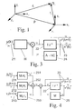
- the condition observer 2 In the phase of greater distance, the state variables are smaller To measure accuracy, the condition observer 2 must settle faster can, i.e. the estimated measurement vectors y * (k) must match the real ones more quickly Measurement vectors y (k) can be approximated. In the immediate vicinity of the docking process the approach speed is low and it is therefore advisable to Condition observers to dimension 2 carriers, so that one through an effective Averaging receives a higher accuracy.
- FIG. 5 shows the state observer 2 according to the system of equations (4) in the form of a program loop 26. In contrast to FIG. 4, this shows that exactly one updated state vector x * is available after each measuring cycle.
- the state variables of the moving body can be used for many Win cases of sufficient accuracy.
- Another advantage of this variant of the method according to the invention is that the approximate position of the next retroreflector R i can also be calculated from the estimated state variables, which means an improvement of the measurement process by suitable selection of the field of view of the laser radar.
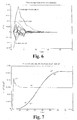
- FIG. 7 shows the manner in which the state observer according to FIG. 5 follows the changing state variables of the moving spaceship. If, for example, the quaternion q 1 (corresponds to the roll angle) changes almost suddenly, the condition observer follows in a relatively short time with an overshoot. At the same time, the quaternion q 2 (corresponds to the pitch angle) changes approximately sinusoidally, and the condition observer can follow very precisely. The estimate of the quaternion q 2 * generated by the state observer is practically equal to the real value q 2 .
- the other state variables also show almost the same behavior, as a result of which the performance of the last variant of the method according to the invention is impressively demonstrated. Similar results are also obtained for the basic variant of the invention. This also applies in the embodiment according to FIG. 4, in which - due to the necessity of a complete series of retroreflector scans in each case - the subsequent behavior of the state observer only has a coarser time grid when the state variables are output.
Landscapes
- Engineering & Computer Science (AREA)
- Remote Sensing (AREA)
- Physics & Mathematics (AREA)
- Electromagnetism (AREA)
- Radar, Positioning & Navigation (AREA)
- Aviation & Aerospace Engineering (AREA)
- Computer Networks & Wireless Communication (AREA)
- General Physics & Mathematics (AREA)
- Automation & Control Theory (AREA)
- Chemical & Material Sciences (AREA)
- Combustion & Propulsion (AREA)
- Optical Radar Systems And Details Thereof (AREA)
Applications Claiming Priority (2)
| Application Number | Priority Date | Filing Date | Title |
|---|---|---|---|
| DE10011890 | 2000-03-03 | ||
| DE10011890A DE10011890C2 (de) | 2000-03-03 | 2000-03-03 | Verfahren zur Bestimmung der Zustandsgrössen eines sich bewegenden starren Körpers im Raum |
Publications (1)
| Publication Number | Publication Date |
|---|---|
| EP1129944A1 true EP1129944A1 (fr) | 2001-09-05 |
Family
ID=7634344
Family Applications (1)
| Application Number | Title | Priority Date | Filing Date |
|---|---|---|---|
| EP01104452A Withdrawn EP1129944A1 (fr) | 2000-03-03 | 2001-02-28 | Parmètres d'état d'un corps en mouvement ( docking, rendezvous ) avec trois rétroréflecteurs et observateur d'état ( Luenberger ) |
Country Status (4)
| Country | Link |
|---|---|
| US (1) | US20010037185A1 (fr) |
| EP (1) | EP1129944A1 (fr) |
| JP (1) | JP2001315698A (fr) |
| DE (1) | DE10011890C2 (fr) |
Cited By (3)
| Publication number | Priority date | Publication date | Assignee | Title |
|---|---|---|---|---|
| WO2005045784A1 (fr) * | 2003-10-31 | 2005-05-19 | Conti Temic Microelectronic Gmbh | Procede et dispositif pour mesurer des distances et/ou des vitesses |
| WO2016116856A1 (fr) * | 2015-01-20 | 2016-07-28 | Politecnico Di Torino | Procédé et système de mesure de la vitesse angulaire d'un corps en orbite dans l'espace |
| CN113443555A (zh) * | 2021-06-24 | 2021-09-28 | 上海振华重工(集团)股份有限公司 | 确定抓斗位置的方法、抓斗位置检测方法及存储介质 |
Families Citing this family (14)
| Publication number | Priority date | Publication date | Assignee | Title |
|---|---|---|---|---|
| DE10034869A1 (de) * | 2000-07-18 | 2002-02-07 | Siemens Ag | Verfahren zum automatischen Gewinnen einer funktionsfähigen Reihenfolge von Prozessen und Werkzeug hierzu |
| US7230689B2 (en) * | 2002-08-26 | 2007-06-12 | Lau Kam C | Multi-dimensional measuring system |
| US7602480B2 (en) * | 2005-10-26 | 2009-10-13 | Alcatel-Lucent Usa Inc. | Method and system for tracking a moving station or target in free space communications |
| DE102012000331B4 (de) | 2012-01-11 | 2018-08-16 | Jena-Optronik Gmbh | Verfahren und Sensorsystem zur Lagebestimmung eines Flugobjekts |
| DE102012111752A1 (de) * | 2012-12-04 | 2014-06-18 | Jena-Optronik Gmbh | Verfahren zur automatischen Korrektur von Ausrichtungsfehlern in Sternsensorsystemen |
| KR102529171B1 (ko) * | 2016-02-26 | 2023-05-04 | 삼성전자주식회사 | 메모리 장치 진단 시스템 |
| US10180686B2 (en) * | 2016-03-17 | 2019-01-15 | Mitsubishi Electric Research Laboratories, Inc. | Concurrent station keeping, attitude control, and momentum management of spacecraft |
| CN109094818B (zh) * | 2018-01-24 | 2021-01-22 | 北京电子工程总体研究所 | 一种空间飞行器的远程交会制导方法 |
| CN108762495B (zh) * | 2018-05-18 | 2021-06-29 | 深圳大学 | 基于手臂动作捕捉的虚拟现实驱动方法及虚拟现实系统 |
| EP3610993B1 (fr) | 2018-08-14 | 2025-04-09 | Beckman Coulter, Inc. | Système de commande de déplacement de mouvement actif d'un robot |
| CN109814583B (zh) * | 2019-01-18 | 2021-08-31 | 东华理工大学 | 基于自主水下机器人航向运动的动态状态反馈控制方法 |
| CN110492815B (zh) * | 2019-08-23 | 2021-02-02 | 哈尔滨工业大学 | 无传感器感应电机极低速稳定性与动态性同步优化方法 |
| CN111531407B (zh) * | 2020-05-08 | 2021-08-17 | 太原理工大学 | 一种基于图像处理的工件姿态快速测量方法 |
| CN112363522B (zh) * | 2020-11-09 | 2022-09-27 | 西北工业大学 | 一种基于混杂强制型观测器的网络化航天器姿态控制方法 |
Citations (6)
| Publication number | Priority date | Publication date | Assignee | Title |
|---|---|---|---|---|
| US4521855A (en) * | 1981-07-27 | 1985-06-04 | Ford Aerospace & Communications Corporation | Electronic on-orbit roll/yaw satellite control |
| US4834531A (en) * | 1985-10-31 | 1989-05-30 | Energy Optics, Incorporated | Dead reckoning optoelectronic intelligent docking system |
| US5020876A (en) * | 1990-02-20 | 1991-06-04 | The United States Of America As Represented By The Administrator Of The National Aeronautics And Space Administration | Standard remote manipulator system docking target augmentation for automated docking |
| US5109345A (en) * | 1990-02-20 | 1992-04-28 | The United States Of America As Represented By The Administrator Of The National Aeronautics And Space Administration | Closed-loop autonomous docking system |
| US5436841A (en) * | 1992-03-16 | 1995-07-25 | Aerospatiale Societe Nationale Industrielle | Method and device for determining the relative position and the relative path of two space vehicles |
| DE19515176A1 (de) * | 1994-06-17 | 1995-12-21 | Trw Inc | Autonomes Rendezvous- und Dockingsystem und Verfahren für dieses |
Family Cites Families (2)
| Publication number | Priority date | Publication date | Assignee | Title |
|---|---|---|---|---|
| JP2669223B2 (ja) * | 1991-10-14 | 1997-10-27 | 三菱電機株式会社 | ランデブードッキング用光学センサー装置 |
| US5334848A (en) * | 1993-04-09 | 1994-08-02 | Trw Inc. | Spacecraft docking sensor system |
-
2000
- 2000-03-03 DE DE10011890A patent/DE10011890C2/de not_active Expired - Fee Related
-
2001
- 2001-02-28 EP EP01104452A patent/EP1129944A1/fr not_active Withdrawn
- 2001-03-02 JP JP2001058386A patent/JP2001315698A/ja active Pending
- 2001-03-02 US US09/798,556 patent/US20010037185A1/en not_active Abandoned
Patent Citations (6)
| Publication number | Priority date | Publication date | Assignee | Title |
|---|---|---|---|---|
| US4521855A (en) * | 1981-07-27 | 1985-06-04 | Ford Aerospace & Communications Corporation | Electronic on-orbit roll/yaw satellite control |
| US4834531A (en) * | 1985-10-31 | 1989-05-30 | Energy Optics, Incorporated | Dead reckoning optoelectronic intelligent docking system |
| US5020876A (en) * | 1990-02-20 | 1991-06-04 | The United States Of America As Represented By The Administrator Of The National Aeronautics And Space Administration | Standard remote manipulator system docking target augmentation for automated docking |
| US5109345A (en) * | 1990-02-20 | 1992-04-28 | The United States Of America As Represented By The Administrator Of The National Aeronautics And Space Administration | Closed-loop autonomous docking system |
| US5436841A (en) * | 1992-03-16 | 1995-07-25 | Aerospatiale Societe Nationale Industrielle | Method and device for determining the relative position and the relative path of two space vehicles |
| DE19515176A1 (de) * | 1994-06-17 | 1995-12-21 | Trw Inc | Autonomes Rendezvous- und Dockingsystem und Verfahren für dieses |
Cited By (4)
| Publication number | Priority date | Publication date | Assignee | Title |
|---|---|---|---|---|
| WO2005045784A1 (fr) * | 2003-10-31 | 2005-05-19 | Conti Temic Microelectronic Gmbh | Procede et dispositif pour mesurer des distances et/ou des vitesses |
| WO2016116856A1 (fr) * | 2015-01-20 | 2016-07-28 | Politecnico Di Torino | Procédé et système de mesure de la vitesse angulaire d'un corps en orbite dans l'espace |
| CN113443555A (zh) * | 2021-06-24 | 2021-09-28 | 上海振华重工(集团)股份有限公司 | 确定抓斗位置的方法、抓斗位置检测方法及存储介质 |
| CN113443555B (zh) * | 2021-06-24 | 2023-11-24 | 上海振华重工(集团)股份有限公司 | 确定抓斗位置的方法、抓斗位置检测方法及存储介质 |
Also Published As
| Publication number | Publication date |
|---|---|
| JP2001315698A (ja) | 2001-11-13 |
| DE10011890C2 (de) | 2003-04-24 |
| DE10011890A1 (de) | 2001-09-13 |
| US20010037185A1 (en) | 2001-11-01 |
Similar Documents
| Publication | Publication Date | Title |
|---|---|---|
| DE10011890C2 (de) | Verfahren zur Bestimmung der Zustandsgrössen eines sich bewegenden starren Körpers im Raum | |
| DE3427020C2 (fr) | ||
| DE68908536T2 (de) | Verfahren und einrichtung zur ermittlung des ortes und der geschwingdigkeit eines zieles in einem inertialraum. | |
| EP0928428B1 (fr) | Procede d'evaluation de la qualite de mesure d'un capteur pour mesurer la distance sur un systeme mobile autonome | |
| WO1993004923A1 (fr) | Dispositif de mesure s'utilisant lors de la regulation de l'orientation d'un satellite stabilise sur trois axes, ainsi que procede d'evaluation, systeme et procede de regulation connexes | |
| WO1989002622A1 (fr) | Dispositif de regulation de valeur de consigne et/ou de stabilisation de corps librement en mouvement a giration latente | |
| EP0762247B1 (fr) | Appareil de mesure de coordonnées avec une commande qui déplace le palpeur de l'appareil de mesure suivant des données des valeurs de consigne | |
| EP0276454A1 (fr) | Système de poursuite d'une cible | |
| EP1094002A2 (fr) | Système et méthode de contrôle d'un satellite | |
| EP1927866A1 (fr) | Procédé de traitement de signaux de capteur basé sur une grille | |
| DE102014103370A1 (de) | Verfahren und Vorrichtung zur zeitdiskreten Steuerung eines Manipulators | |
| WO2019149664A1 (fr) | Procédé de détermination d'une variation temporelle d'une grandeur de mesure, système de pronostic, système de commande d'actionneur, procédé d'apprentissage du système de commande d'actionneur, système d'apprentissage, programme d'ordinateur et support d'informations lisible par machine | |
| DE3442598A1 (de) | Leitsystem | |
| DE102007007266B4 (de) | Verfahren zum Auswerten von Sensormesswerten | |
| EP1515159B1 (fr) | Méthode pour réduire le centroide doppler pour des systèmes radar coherent à impulsion | |
| DE4218599C2 (de) | Navigations- und Führungssystem für autonome, mobile Roboter | |
| DE19645556A1 (de) | Vorrichtung zur Erzeugung von Lenksignalen für zielverfolgende Flugkörper | |
| EP1186908A2 (fr) | Procédé de poursuite d'une cible mobile | |
| DE19601846A1 (de) | Verfahren zum Lenken und Einstellen der Fluglage von Raketen | |
| EP0207521B1 (fr) | Système de mesure de cible | |
| EP1522873A1 (fr) | Appareil de localisation à multi-détecteur | |
| EP3628964B1 (fr) | Système de manipulation opto-électromécanique de faisceaux | |
| DE10130623C1 (de) | Verfahren zur Bestimmung der Zustandsgrößen eines starren Körpers im Raum mittels eines Videometers | |
| DE69426738T2 (de) | Navigationssystem mit passivem Bildsensor | |
| DE102023128626A1 (de) | Multimodale Zustandsschätzung mit maskierten Sensormessungen |
Legal Events
| Date | Code | Title | Description |
|---|---|---|---|
| PUAI | Public reference made under article 153(3) epc to a published international application that has entered the european phase |
Free format text: ORIGINAL CODE: 0009012 |
|
| AK | Designated contracting states |
Kind code of ref document: A1 Designated state(s): FR GB IT Kind code of ref document: A1 Designated state(s): AT BE CH CY DE DK ES FI FR GB GR IE IT LI LU MC NL PT SE TR |
|
| AX | Request for extension of the european patent |
Free format text: AL;LT;LV;MK;RO;SI |
|
| 17P | Request for examination filed |
Effective date: 20020226 |
|
| AKX | Designation fees paid |
Free format text: FR GB IT |
|
| REG | Reference to a national code |
Ref country code: DE Ref legal event code: 8566 |
|
| STAA | Information on the status of an ep patent application or granted ep patent |
Free format text: STATUS: THE APPLICATION IS DEEMED TO BE WITHDRAWN |
|
| 18D | Application deemed to be withdrawn |
Effective date: 20030902 |